We use several methods to create a hole from the wellbore through the casing and any cement sheath into the producing zone, such as shaped perforating charges, bullet guns, and abrasive jets. These methods are called perforating methods. Perforations create conduits into the reservoir that allow hydrocarbon recovery and influence it. Different perforating requirements are needed for each of the three main types of completions: natural, stimulated, and sand control. In this article, we shall talk about the following methods:
- Bullet Perforators
- Shaped Charge
- Hydraulic Sand-Jet Perforating
- Chemical Perforators
- Mechanical Perforators
- Laser Method
- Horizontal-Oriented Perforating System
Bullet Perforators
Before the advent of completions lined with cemented casing pipe, the application for mechanical cutters was to cut through the casing and cement to allow production. However, in 1926, the first patent for perforating with a bullet gun was granted. Despite this, it was not tested until 1932, when Lane-Wells Company (later acquired by Dresser Industries) began offering bullet perforating services to the oil industry. The bullet casing guns were similar in operation to the perforation guns used today for sample taking.
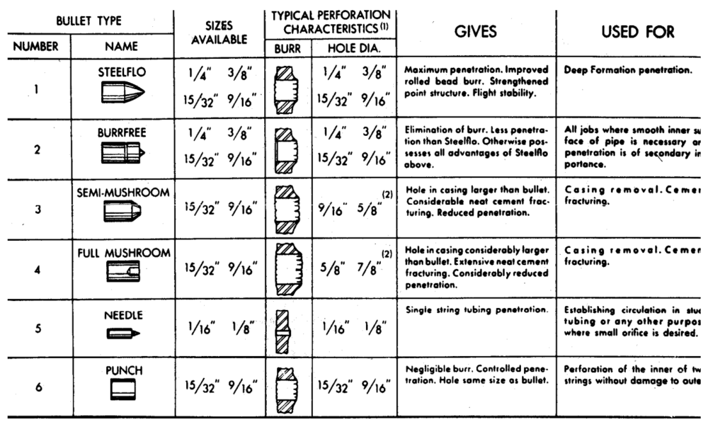
In the past, companies used bullet perforators to penetrate well casings, cement sheaths, and rock formations by firing hardened steel bullets from a short barrel using a black powder charge. However, these perforators were not very effective in harder rocks. In addition, bullets often were recovered from the well, implying unsuccessful casing penetration.
Although oil and gas companies continued using it until the 1960s, they gradually replaced it with explosive-shaped charges from the mid-1950s. Nowadays, companies are only using bullet perforators in specific cases, such as the perforation of certain soft formations, the placement of radio-active marker bullets for compaction monitoring, or where there is a requirement for circular and burr-free holes. Finally, remember the following:
- Often, we use the bullet method to perforate the casing in unconsolidated formations.
- Bullets lose velocity when perforation gun clearance >0.5 in.
- Bullets plug the end of the flow channel.
- It is cheaper to use
- This perforator is rare today.
Shaped Charge Or Jet Well Perforation Method
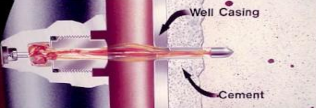
The first shaped charge guns consisted of large diameter tubular steel carriers in that mounts the charge. We can run these casing guns on wirelines and fire it electrically like that employed today. The large diameter and heavy weight of the guns combined with the pressure control problems generally precluded their use in completed wells or with significant underbalanced pressures in the borehole. These guns were usually run in overbalanced, mud-filled holes, and the casing was perforated before running the completion.
After the development of larger guns, smaller-diameter, lightweight guns were created that could be run on a 4.76 mm (3/16″) or 5.56 mm (7/32″) diameter cable. These smaller casing guns were small enough to run through the completion. In addition, using a small diameter cable with pressure control equipment allowed perforating the well safely underbalanced condition. However, the limited charge size that the small-diameter carriers could accommodate resulted in suboptimal gun performance.
Over the past decade, tubing-conveyed perforating has combined the benefits of large-diameter carriers and underbalanced perforating. This will allow the gun to run into the well while suspended from the completion. Finally, remember the following:
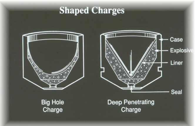
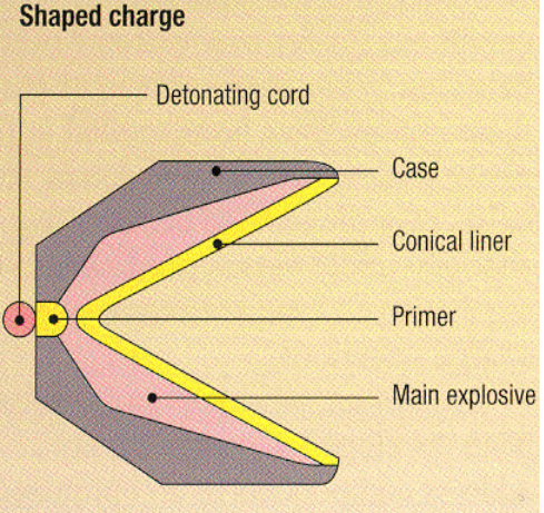
- It uses a shaped charge contained in a perforating gun assembly.
- A high-pressure jet will penetrate the casing or liner to shoot into the reservoir formation to form channels.
- The placement of the gun assembly varies based on wellbore conditions, and may be in wireline, production tubing, or coiled tubing.
Cutting and Severing
The shaped charges design allows it to penetrate a specific thickness of steel. In addition, it allows cutting the inner of two tubular strings without causing any damage to the outer string. These cutters have an outside diameter slightly smaller than the tubular size they will cut. In addition, they cannot be used below certain restrictions.
It is important to note that we should only use cutters and severing tools for drill pipe and drill collar in open holes. Any attempts to use them in any other setting could cause damage to the casing. When using shaped charge cutters, put the pipe under tension and fire the cutter in the pipe’s body where the thickness of the steel is almost negligible.
Severing tools are not shaped charges but are tubes filled with up to 4 kg of explosive segments, which produce an unfocussed blast. When using a severing tool, the pipe to be cut is placed under tension, and the shot is positioned inside a tool joint. The blast deforms and splits the tool joint, allowing the string to part. Severing tools are available for tool joints and drill collars up to 12″ in diameter.
Hydraulic Sand-Jet Perforating – Abrasive Perforating Method
This well perforation method uses a fluid jet at high pressure containing abrasive particles to erode the casing and formation. Previously, this process was performed using a traditional workstring, which needed a hoist and thus was very costly and time-consuming. The process was also slower than jet perforating, taking around 5-10 minutes per perforation. As a result, it was not widely adopted. However, there has been an interest in the technique in recent years. This is because we can use coiled tubing to carry out the perforation. In addition, it will have the potential to be more cost-effective. Currently, it is being studied as a research subject.
Recent abrasive jetting experiments have demonstrated that jetted holes are far more stable and clean than perforated holes. After gravel packing, the jetted method also showed no impairment, while tunnel plugging was observed for the gravel-packed perforated tunnel.
The productivity of a gravel-packed cased hole perforated well has been compared to that of a gravel-packed cased hole slot cut well. The study found that replacing the actual perforation configuration with a multiple-slot configuration would significantly improve the well’s productivity. This is based on the presumption that a perforated well has a reduced inflow area due to tunnel plugging and, as suggested from the WIQI data analysis from the actual wells, a reduced gravel permeability possible caused by invasion of fines created during this process. The slotting technique using abrasives is likely sufficiently mature for implementation in the field.
Chemical Perforators
These devices employ a corrosive fluid jet to etch a casing hole. To clarify, these tools are mainly used to create a path for communication between the wellbore and the annulus. Unlike production tubing punches, they are not intended for production perforating. The resulting holes are both clean and burr-free, making multiple perforations at the same depth possible. For more details, check the chemical cutter article.
Mechanical Punchers Well Perforation Method
Wireline conveyed mechanical well perforating (punches) method is available from several industry service companies. These tools are primarily intended for punching holes in standard and heavy-weight tubing.
Mechanical punches are usually lowered into the well using either wire or slickline and set to a specific depth. The tool contains jars that trigger a power charge, forcing a piston downwards. This piston, in turn, drives a wedge to push an orifice insert through the production tubing.
The main benefits of mechanical punches are:
- The risk of inadvertently perforating the production casing is negligible;
- They are less costly than shaped charge punches. During mechanical punch operations, radio silence is necessary, as with other techniques using explosive perforating charges.
Several companies have employed mechanical tubing punches to:
- Provide access to the tubing/casing annulus to facilitate well-kill operations;
- Avoid pulling a wet string;
- Lower the gas injection point in a gas lift well. Check valves and pack-off gas lift can also be installed;
- Permit production through a completion tailpipe that has become plugged.
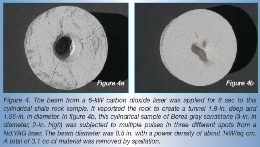
Perforating with Laser
Laser perforation is a technique used to create a flow path between the reservoir and the wellbore, which allows the reservoir fluid to flow into the wellbore. Compared to conventional methods, laser perforation offers several benefits, such as low energy consumption, remote energy delivery using optical fibers, reduced working days, precise control over hole geometry, lower costs, and significantly faster perforating speed.
- The conventional explosive charge perforation method reduces the rock permeability.
- Laser method increases the rock permeability (absolute permeability), increasing a well’s oil or gas production rate.
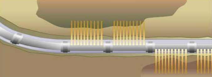
Horizontal-Oriented Perforating System
This method aims to perform oriented perforating.
- It incorporates a series of swiveled gun connectors containing internal explosive transfer devices and an internally contained gun weighting system.
- This system incorporates a series of short gun sections that rotate to the desired orientation, providing the optimum shot pattern and maximizing reservoir production.
Benefits
- Live well intervention systems can operate efficiently with HOPS, as it is specifically designed for this purpose.
- The orientation accuracy range has been improved to ± 5° for wells with a deviation of 25° or more.
- It is possible to use this technology on different types of pipes, including coiled tubing, wireline, slickline, or jointed pipe.
- There is no need for external weight bars, eliminating gaps between loaded sections and lost shots.
When consulting service companies for additional information, specify the following: application, grade of steel, tubing size, weight, and ID restrictions.