Blowout Preventers (BOP) Stack is one of the rig components used to seal the wellbore and thereby contain a kick ( check drilling kick). Two main types of BOP preventers are used in the industry (both types are discussed below). This article will discuss its BOP blowout preventers stack classification, components & types.
API Classification For BOP Blowout Preventers Components
API classification for BOP blowout preventer equipment is based on working pressure ratings. BOP stacks are rated to 2000 (2m), 3,000 (3m), 5,000 (5m), 10,000 (10m), or 15,000 (15m) psi.
API Codes For BOP Stack Components
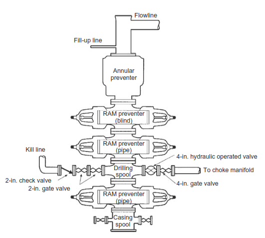
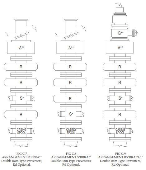
As we mentioned, blowout preventer stacks are rated to 2000, 3,000, 5,000, 10,000, or 15,000 psi. A preventer stack normally consists of an annular BOP preventer on top, followed by one or more (typically up to three) ram-type preventers (Fig.1). The inclusion of a full-bore drilling spool makes it possible to connect the kill and choke lines (Adams 1979b, 1980a).
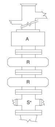
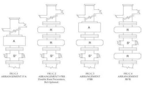
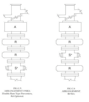
- A= annular type blowout preventer.
- G= rotating Drilling head.
- R=single ram-type preventer with one set of rams, either blank or for pipe, as the operator prefers.
- Rd = double ram-type preventer with two sets of rams positioned according to the operator’s choice.
- Rt = triple ram-type preventer with three sets of rams positioned according to the operator’s choice.
- S =drilling spool with side outlet connections for the choke and kill lines.
- M = 1000 psi rated working pressure.
How To Specify BOP Stack
- Components are listed reading upward from the uppermost piece of permanent wellhead equipment or the bottom of the BOP blowout preventers stack.
- A blowout preventer stack may be fully identified by a very simple designation, such as:
5M -13 5/ 8 – SRRA
This preventer stack would be rated 5000 psi working pressure, would have an internal bore of 13 5 /8 inches, and would be arranged as in the below Figure.
BOP Stack Arrangements
BOP blowout preventers stack arrangements other than those illustrated may be equally adequate in meeting well requirements and promoting safety and efficiency.
An important consideration for designing the BOP blowout preventer stack arrangement is its space under the rig. Even after setting multiple casings (with each casing head adding to the total height of the equipment), it still must be possible to accommodate the full preventer stack.
BOP Blowout Preventers Types
Annular Preventers Type
This preventer can seal around any object with a circular (or nearly circular) cross-section and over an empty hole. It can also seal around Kelly (hexagonal shapes are better than square shapes). Because of its variable diameter, it also allows tool joints to pass when the pipe is being lowered into the hole while surface pressure is present, an operation called stripping (also check well control stripping procedure) (overcoming the pressure area forces with the pipe weight) or snubbing (forcing the pipe into the hole because the weight is not enough to overcome the pressure area forces) (Fig.6).
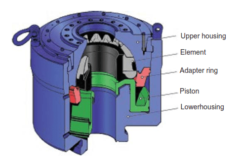
Operating pressure is generally lower than that used for ram-type preventers because the piston area is far larger. The pressure can also be adjusted to ease the tubular passage while stripping into the well by reducing friction. Still, it is necessary to lubricate the pipe while stripping it into the well. Drilling mud or water can be used for lubrication.
The operating principle of this type of preventer is simple. Hydraulic pressure is applied to the low side of a wedge-shaped piston. The circular wedge then forces the sealing element toward the inside. Frequent closing and opening of the sealing element will significantly shorten its life. In particular, closing over an empty hole hurts the sealing element. For this reason, it is common not to test annular preventers as often as ram-type preventers.
Ram Type Preventers
Rams are found on most BOP blowout preventer stacks, except in some low-pressure applications. They are closed by hydraulic pressure, which forces the set of rams together from both sides. As a backup measure, they can also be manually closed (Fig. 10.7).
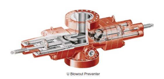
Sealing is achieved between the upper surface of the ram and the preventer body and between the sealing surfaces of the ram. Different kinds of rams are available. Pipe rams have a semicircular groove that enables sealing around the pipe. They are designed for sealing around a specific diameter of the pipe. Therefore, changing the rams can be necessary when switching to a different-diameter drill pipe or closing in a well with drill collars or casing (or other equipment) within the preventer stack. Furthermore, no tool joints should be located within the BOP blowout preventers stack while shutting in the well. This is easily avoided by lowering or lifting the top tool joint of the drill string to an easily accessible working height at the rig floor.
Most modern ram-type preventers have a built-in secondary seal consisting of a plastic sealing material forced against the sealing surfaces by twisting a bolt. This seal is designed as a contingency measure in case the ram preventer starts to leak during a well-control operation (Adams 2005).
Ram type preventers should be equipped with extension hand wheels hydraulic locks.
Variable Bore Rams Type
The variable-bore ram type has flexible steel fingers that can seal around pipe diameters smaller than the ram itself. With a standard pipe ram, it is possible to hang a drill string on the ram. A variable-bore ram, on the other hand, is not strong enough to support a drill string.
Blind & Shear Rams Type
Blind rams type are used to seal over an open hole. They have a sealing surface that is pressed together when actuated. A special kind of blind ram is called a shear ram. Blind shear rams have cutting edges and can shear through drill pipe (and small-diameter drill collar) and seal over it. Because this option eliminates the possibility of circulating through the drill pipe, the shear ram is considered an option of last resort. Typically, these are used in offshore rigs.
BOP Blowout Preventer Spare Parts
The following recommended minimum BOP blowout preventer spare parts approved for the service intended should be available at each rig:
- A complete set of drill pipe rams and ram rubbers for each size of drill pipe being used,
- A complete set of bonnet or door seals for each size and type of ram preventer being used,
- Plastic packing for BOP blowout preventers secondary seals,
- Ring gaskets to fit flange connections and
- Appropriate spare parts for annular, when used.
When storing blowout preventer metal parts and related equipment, they should be coated with a protective coating to prevent rust.
Drilling Spools
While choke and kill lines may be connected to side outlets of the BOP blowout preventers stack, many operators prefer that these lines be connected to a drilling spool installed at least one preventer capable of closing on the pipe below. Utilizing the blowout BOP side outlet reduces the number of stack connections by eliminating the drilling spool and shortens the overall height. The reasons for using a drilling spool are to localize possible erosion in the less expensive spool and to allow additional space between rams to facilitate stripping operations.
According to API, drilling spools should meet the following minimum specifications:
- Have side outlets smaller than 2″ nominal diameter and be flanged, studded, or clamped for API Class 2M, 3M, and 5M. For
- API Class 10M and 15M installations should have a minimum of two side outlets, one 3″ and one 2″ nominal diameter.
- Have a vertical bore diameter equal to the maximum bore of the uppermost casing head.
- Have a working pressure rating equal to the rated working pressure of the attached blowout preventer.
ENI Recommendations For Blowout Preventers BOP Stack Operations
From my point of view, Eni presented good and useful considerations while blowout BOP Design & Operations, which are as follows:
BOP Blowout Preventers For Land Rigs, Jack-Up Rigs, And Fixed Platform
The pressure rating requirement for blowout BOP equipment is based on the ‘maximum anticipated surface pressure. Projects that require a different working pressure in the whole system shall be agreed upon by the Company and Drilling Contractor.
The minimum BOP stack requirements are as follows:
Firstly, A 5,000 psi WP stack should have at least:
- Two ram-type preventers (one shear ram and one pipe ram).
- One 2,000 psi annular type.
Secondly, A 10,000 psi stack should have at least:
- Three ram-type preventers (one shear ram and two pipe ram).
- One 5,000 psi annular type.
Thirdly, A 15,000 psi stack should have at least:
- Four ram-type preventers (one shear ram and three pipe ram)
- One 10,000psi annular type.
Pipe Rams
- While drilling, all pipe ram preventers shall always be equipped with the correct sized rams to match the drill pipe being used. If a tapered drill string is used, e.g., 3” and 5”, one set of rams will be dressed to match the smaller drill pipe size (API drill pipe specs). During casing jobs or production testing, the choice of pipe rams shall be defined by the Company, depending on the external diameter(s) of the casing/drilling/testing string(s) in the operation and blowout BOP stack composition.
- At least one ram preventer below the shear rams shall be equipped with fixed pipe rams to fit the upper drill pipe. The minimum distance between shear and hang-off pipe rams shall be 80cm (30”).
- The use of variable bore rams (VBRs) is acceptable, but they should not be used for hanging off pipe which is near to the lower end of their operating range.
Rig Site Maintenance
Rig site repair of BOP equipment is limited to replacing worn or damaged parts. Under no circumstances is welding or cutting to be performed on any BOP equipment. Replacement parts should only be those supplied or recommended by the equipment manufacturer.
Choke & Kill Lines
- Each choke and kill line BOP outlet shall be equipped with two full-bore valves, the outer valve of which will be hydraulically operated (preferably fail-safe closed).
- The minimum diameter of the choke line will be a 3″ ID, while the kill line should have not less than a 2″ ID. Articulated choke lines (Chiksan) are unacceptable unless derogation is agreed upon for a particular application.
- Several various arrangements in the position of the choke and kill line outlets are used in blowout BOP stack configurations throughout the oil industry. The rig operating manual should highlight these variations, their limitations, and all the potential uses of a particular layout.
- Eni-AGIP recommends that the positioning of choke and kill line outlets below the lowest pipe rams be avoided on a four-ram BOP stack, as these are like the last resort ‘Master Valve’ of the BOP stack.
- Including shear rams requires the choke and kill lines positions to be such that the direct circulation of the kick through the drill pipe stub after shear rams activation can be performed with the drill string hang-off on the closed pipe rams and holding pressure.
BOP Blowout Preventers For Floating Rigs
The minimum BOP stack requirements for floating rigs are as follows:
Firstly, A 10,000 psi stack should have at least:
- Four ram-type preventers (one shear ram and three pipe rams)
- One or preferably two 5,000 psi annular type preventers (one annular retrievable on Lower Marine Drilling Riser Package).
Secondly, A 15,000 psi stack should have at least:
- Four ram-type preventers (one shear ram and three pipe rams)
- Two 10,000 psi annular type blowout preventers (one annular retrievable on the Lower Marine Riser Package).
b) The upper hydraulic connector shall have a pressure rating equal to or exceeding the working pressure of the bag-type preventers.
Pipe Rams
Any type of blowout preventer stack will contain pipe rams that can close on every size of drill pipe/tubing run through the stack. The use of VBRs is acceptable but should not be used for hanging off pipes near the lower end of their operating range. At least one ram preventer below the shear rams shall be equipped with fixed pipe rams to fit the upper drill pipe. The minimum distance between shear and hang-off pipe rams shall be 80cm (30”).
Choke & Kill Lines
Each choke and kill line BOP outlet shall have two fail-safe, remotely controlled gate valves rated to the BOP working pressure. The valves shall be fail-safe in the closed position.
The minimum diameter of choke/kill lines will be 3″ ID. The function of each line must be interchangeable at the surface to line up with both the rig pumps and the choke manifold.
Some various arrangements in the position of choke/kill line outlets are used in BOP stack configurations throughout the oil industry. The rig operating manual should highlight these variations, their limitation, and all the potential uses of the particular Layout.
The inclusion of shear rams requires to choke and kill line positioning such that the direct circulation of the kick through the drill pipe stub after shear rams activation can be performed with the drill string hang-off on closed pipe rams holding pressure. Eni-Agip recommends that choke and kill line outlets are positioned above the lowest pipe rams as these are like the last resort ‘Master Valve’ of the blowout BOP stack.
Deep Water Operations
For deepwater operation, it is recommended to use a BOP stack equipped with an injection line to pump methanol or glycol to reduce the likelihood of hydrates forming during well control operations. It is also recommended that pressure and temperature gauges be located on the blowout BOP stack.
Ref: Applied Drilling Engineering, Eni Drilling Operations Manual, Aramco Drilling Manual 2006