Take into your considerations:
- Good practice when unloading cement is to blow the first few sacks of cement through the lines in order to prevent moisture contaminated cement from collecting in the tanks. Off-loaded cement should be blown into empty, clean tanks.
- If possible, avoid storing cement for long periods. Alternate tank usage systematically and check them. Cement will pack when stored for a long periods and it should be aerated for half hour once a week.
- To prevent condensation in the cement tanks and lines, pressure should be maintained on the system at all times. This will prevent breathing which can lead to condensation.
- The Company Completion & Drilling Supervisor is directly responsible for the proper inventory of cement and additives required before each job.
- It is necessary to send a sample of cement, mud, barite and mixing water to the Company Drilling Office where it shall be tested. Check the drill water for chloride content, calcium and pH.
- Prepare graph, one with casing weight in mud versus depth and the other with steel displacement versus depth. A copy of these graphs must be given to the Driller and to the Mud Engineer.
Installation Patterns (For Mechanical Cementing Aids)
The selection of the proper installation pattern for mechanical cementing aids i.e. centralises, scratchers, turbolisers, etc. is essential to optimise casing running and cementing results.
Cementing aids and their installation pattern are a function of operational conditions and cementing objectives. Because of these variable factors, pattern philosophy is different from case to case. The Drilling Programme must specify type, quantity and installation pattern of mechanical cementing pieces, with due consideration to eventual modifications after caliper log evaluation.The following cases described below:
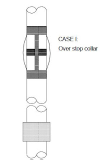
Case I
The simplest and most practical is the installation of centralisers directly over stop collars. Installation on the racks is advisable as it saves time. This pattern is not recommended in close-tolerance conditions, i.e. saves 7″ rig casing in an 81/2″ hole.
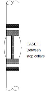
Case II
In close-tolerance conditions, the centralisers should be positioned between two stop collars. This pattern may be installed on the rack.
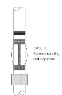
Case III
In this alternate close-tolerance pattern, the centralisers are installed between a stop collar and the casing coupling. This pattern allows limited centraliser travel and requires only one stop collar per centraliser, reducing equipment cost. Installation should not be performed on the rack.
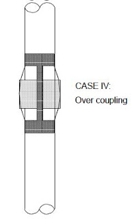
Case IV
Centralisers can be installed over the casing coupling but this reduces annular flow and the positive stand-off provided by the casing coupling and requires extra rig time. Weatherford do not recommend this pattern for close-tolerance conditions or where ST-I and/or SP-I bows are used.
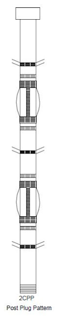
Post Plug Pattern
This pattern (Refer to figure 12.b) is recommended throughout the entire cement column to promote improved cement-to-formation bonding in strings where casing can be reciprocated in 30 to 40 ft cycles. The post-plug pattern uses at least one centraliser per joint and free-tomove scratchers, separated by stop collars installed approximately 10ft (3m) apart.
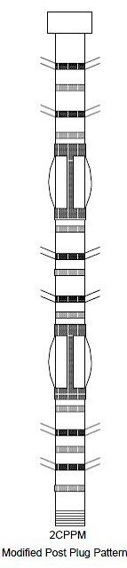
The Modified Post-Plug pattern requires two centralisers per joint in conjunction with multiple scratchers and stop collars placed 5ft (1.5m) apart. Wellbore wipers can replace the scratchers for particular applications.
The following codes will be used to describe the number of centralizers per casing:
1C: one centraliser per joint
2C: two centralisers per joint
3C: three centralisers per joint.
The following codes will be used to indicate the centralisers spacing:
C1: one centraliser each joint
C2: one centraliser every two joints
C3: one centraliser every three joints.
Example: 2C3 = two centralizer every three joints.
Consider the following while deciding the installation patterns
1) The use of spiral centralizers is recommended in each of the patterns where close tolerance conditions exist.
2) Alternate left/right handed spiral centralizers are used in special applications e.g. casing liner (One of Types Of Casing), deviated wells, production strings, improvement of hydraulic displacement, etc.
3) For open hole intervals, spiral bow type centralizers will be used unless otherwise specified. Straight type bows will be used for wash-out sections, unconsolidated formations, etc.
4) Rigid type centralizers (Positive) are never allowed to enter open hole intervals.
5) In deeper wells, where high-rating casing equipment is used, Positive type centralizers OD for free passage through clamp’s slips should be considered. If not applicable, spring bows are recommended and also in casing to casing intervals.
6) Maximize centralization when special equipment/tools/zone are predicted i.e. stage tools, liner hanger, ECIP, GOC, WOC, etc.
7) Special CRC stop collars, (without nails) are essential for CRA (Corrosion Resistant Alloys) casing.