The drilling program is the engineering design for the process of drilling and completion of the wellbore. The plan includes many data including well trajectory, casing design, mud program, well control, Drilling Bit Selection, geological data, formation gradient estimations, economics, and special procedures that shall be followed during the construction of the well. Although drilling procedures are carefully developed, they are subject to be modified according to well conditions.

The preparation of good Drilling Programme is very vital for safe and effective drilling operation. Drilling Program shall include minimum 12 main parts:
- Well General Data
- Well objectives
- Casing Design
- Wellhead Design
- Mud program.
- BOP stack Configuration
- Cementing Design
- Directional Plan & Well Trajectory Calculations
- Survey requirements (Drilling survey calculations)
- Drilling Bit and Hydraulics in drilling programme
- Evaluation requirements
- Casing Design
- Estimation of well cost
All Drilling Programs will contain the above-mentioned data in some form. We shall discuss them in more detail below. Specialized wells could also contain other data.
WELL GENERAL DETAILS
This section includes simple info as well coordinates, field/structure, type, well depth, operator and owner Co. data. A typical layout of this is shown below:
- Location
- Field/ Structure
- Coordinates of the well
- Well Name
- Well Type (Development – Exploratory)
- Water depth (for offshore wells)
- Total Depth
- Operator oil or gas Company
- Target Tolerance
- Rig Name
- Type of the drilling rig
WELL OBJECTIVES
The well objective is mainly provided by the exploration division. Below, an example of the well objective that shows the purpose of drilling such well.
“To test hydrocarbon prospects of fore reef facies in Oligocene, Miocene and sedimentary in Eocene section of LSM feature”.
CASING PROGRAM IN DRILLING
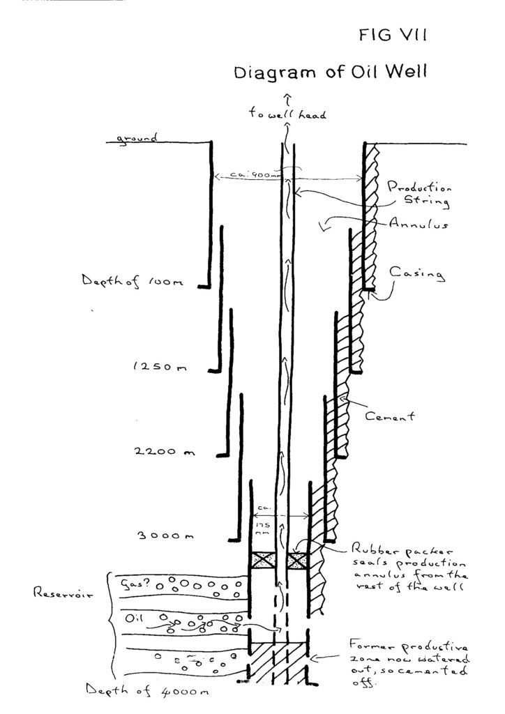
Casing Function
Casing pipes (Types of casing) are put into a wellbore for many reasons including:
- To isolate troublesome or unstable formations,
- isolate different pressures zones,
- support wellhead and blowout preventer and more. (Check casing functions)
Pore Pressure Calculations
Most of the decisions pertaining to casing design depend on formation pore pressure. It is imperative, therefore, that pore pressures be determined or estimated as accurately as possible. The two ways to get such pore pressure data for drilling program are geophysical/geological data and offset well data. Offset wells introduce more realistic data, but sometimes you need to drill exploratory wells that have no offset data and an estimation process of pore pressure shall be done by analyzing seismic data with certain software.
Seismic data is utilized in the exploration phase before drilling to find potential hydrocarbon traps and to determine formation tops in the lithological column. It can also be utilized to calculate pore pressure and hence an indication of any pore pressure abnormalities.
Formation Fracture Pressure Calculations
We can estimate Formation fracture pressure using anticipated geology and offset well Data. Most rocks of a certain type will exhibit typical characteristics. This can be used to assist in fracture gradient Determination. Its importance is that it helps greatly in selecting casing seat depths. Once we perform leak-off test, it will be easy to estimate the fracture pressure in other depths of the well using equations as ’Daines’ with values of Poisson’s Ratio for given formations. In the case of continuous depositional basins, Eaton’s equation with suitable modification can be used for the estimation of the fracture pressure gradient.
Casing Setting Depths
After the pore pressure and fracture pressure charts have been performed and included in the drilling program, the Drilling Engineer should liaise with Production Engineers to decide on the likely size of the final production conduit so as to decide about the different casing sizes required to be lowered at various casing seats selected.
The setting depth will depend on competent formations with high fracture gradients, lengths of open hole sections and requirements of cementing programs, and other anticipated downhole problems.
Casing Design in The Drilling Program
The casing design must follow certain criteria that include:
- Casing Burst Pressure
- Casing Collapse Pressure
- Casing tensile Pressure
- Other loadings (Casing Biaxial Loads)
Burst is drill pipe failure that occurs when the pressure inside the pipe is greater than the internal yield value of the pipe plus the pressure outside the pipe.
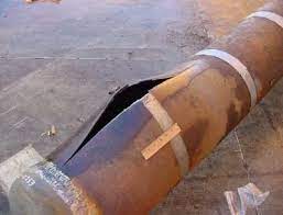
Here, we shall consider both the formation at the shoe and the casing burst. In such design, we shall assume a situation where both formation and casing are able to withstand the resultant pressure caused by a full gas column to the surface plus the pressure caused by the circulation of such gas to the surface. However, in some cases, the casing may have to be designed on a limited kick basis which has been discussed in the Casing Loads Design.
The collapse will occur when the external force on the pipe is greater than the combination of the internal pressure plus the collapse rating of the pipe. It occurs as a result of either or a combination of:
- Reduction in hydrostatic head exerted by the fluid inside the pipe.
- Increase in hydrostatic head exerted by the fluid outside the pipe.
- Mechanical forces created by plastic formations, flowing salts etc.
The above three factors can result from the following situations:
- Inadequate fill-up when running casing
- Casing Corrosion will eventually reduce the CSG collapse.
- Lost circulation
- Casing wear
- Cementing in drilling
- High drawdowns for testing purposes. It is generally accepted that an exploratory well will not be subjected to high drawdowns but this should be considered for development wells.
- Air drilling. We have to consider wear allowance caused by lubricity loss plus the complete evacuation.
- Halite sections
- Acidising or hydo fracking a horizon could result in an increase in external loading to a depth above the packer if a path of communication exists.
- Similarly squeeze cementing could increase external loadings above or below packers.
For most wells, we are considering only the first three conditions.
Tensile failure will occur if the pull exerted on the pipe is too great for the tensile strength of the pipe or coupling. For designing the pipe in tension,tensile loads on the casing should be calculated at the following stages:
- When tripping the pipe
- When cementing
- When pressure testing (drilling phase)
WELLHEAD SELECTION
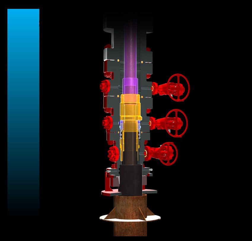
After finalizing the casing design, we have all the information required to allow us for the selection of wellhead. The wellhead must be of the correct pressure rating, designed for the desired application like (H2S), and be able to accommodate all designed and contingent casing strings types.
Having selected a wellhead, its specification should be included in the Drilling Program along with a sectional view of its component stack up.
BOP REQUIREMENT
The Blow Out Preventer Stack requirement for a certain well shall rely on the company policy and anticipated BHPs. Surface holes have either no BOP requirement or will need to use a diverter drilling system.
CEMENTING DESIGN PROGRAMME
The main taget of CMT is to isolate zones in the well. The effectiveness of this zonal isolation depends on three main factors all of which must be considered at the planning stage.
- Casing accessories selection (Centralizers, Scratchers, Cement plugs, ……)
- Cement Calculations & Slurry design
- The Cement Placement Methods
- Displacement Methods
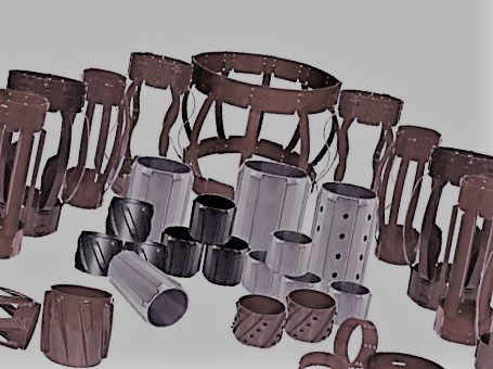
Casing Accessories
Having designed the cement requirements for the well in the drilling program, we need now to look at the accessories that we will use to ensure good cementation. The main accessories used are listed below:
- The guide shoe is the simplest. It merely serves as an aid to guiding the casing in the open hole and has a hole in the middle which allows the mud to pass freely through the string.
- The float shoe is similar, externally, to the guide shoe but contains a non-return valve that allows fluid to flow out of the casing but not into it
- A differential fill-up shoe uses a valve which allows mud to flow into the casing to keep it partially full.
- The automatic fill shoe is also designed to avoid having to fill up the casing all the time from the surface.
- Float Collars are usually placed at one or two joints above the casing shoe. They serve as a stop for the cement wiper plug so that all the slurry is not displaced into the annulus.
- Stage collars are used to locate two distinct separate columns of cement in the annulus when one continuous column would produce too much hydrostatic pressure on the formation or specialized zonal isolation, or communication is required.
- Centralizers are placed on the outside of the casing to keep it concentric with the hole.
- Wiper Plugs have hollow drillable alloy interior and rubber outer fins to wipe clean the casing walls.
Slurry Design
Oil well cement slurry consists of cement, water and additives. The first calculation that we must make in cement design program is to calculate the volumes required. Definitions of some of the important slurry properties are discussed in detail in (Gas & Oil Well Cement Properties Guide | 7 Properties)
Displacement Method:
Cement should be displaced in a state of turbulent flow. Since displacement is usually done using rig pumps, achieving turbulent flow is usually not a problem. In case there is difficulty in achieving turbulent flow with the existing rig mud pump, the cement should be displaced in a plug flow regime.
DIRECTIONAL DRILLING PROGRAM

Directional drilling has now become an essential element in oilfield development, both onshore and offshore rigs. The application of directional drilling can be grouped into the following categories:-
- Sidetracking Drilling
- Controlling vertical holes
- Offshore development drilling3
- Drilling beneath inaccessible locations
- Relief well drilling.
- Horizontal drilling
- Drilling to avoid geological problems
Assuming that a target rig site has been selected, for directional planning considerations, the values that must be identified are as follows;
- Lateral or horizontal displacement from the target to a vertical line from the rig site.
- Kick off point (KOP) Desired build angle rate
- Final drift angle
- Plan type: Straight kick Vs Curve
- Desired drop angle rate in case of ’S’ curve.
Careful planning before the directional well is spudded can lead to substantial savings in the cost of drilling. There are many factors that influence the well trajectory. Some of these may be difficult to estimate (eg. the amount of bit walk which may occur in certain formations). The experience gained from drilling previous directional wells in the same area is, therefore, very useful and should be incorporated into the planning stage of the next well.
SURVEY REQUIREMENTS IN THE DRILLING PROGRAM
In order of increasing complication, the five different methods of the survey are as follows:
- Totcos are clockwork units which measure hole angle by using a pendulum mechanism with a pin on the end. They are crude but effective and since they only measure hole angle there is no need for monel drill collars in the Bottom Hole Assembly to overcome magnetic influences.
- Magnetic single shots have magnetic compasses built into them, in addition to the angle measuring units. Information is gathered using a small camera in the instrument, which takes a photograph of the compass heading and attitude.
- Magnetic multishots are similar in principle to the magnetic single shot but with the additional ability to record magnetic inclination and direction on a film strip at regular depth intervals.
- Electronic multishots measure survey data using triaxial magnetometers which measure components of the earth’s magnetic field and triaxial accelerometers which measure components of the force of gravity. These components are then interpreted to give inclination and direction.
- Directional MWD in the form of drill collar, is a part of the BHA and measures survey data while drilling. The sensors (magnometer and accelerators) used in these tools are identical to the ones used in the electronic multishots.
DRILLING MUD PROGRAM
In practice, mud programming can be broken down as follows:
- Determination of mud weight requirement to maintain primary well control.
- Determination of suitable ‘trip margin’ which is added to the primary well control mud weight to give a programmed mud weight.
- Confirmation that this mud weight does not exceed formation fracture strengths when considered in a dynamic mode.
- Analysis of formations to be drilled and the likely reaction of these to the available drilling fluid alternatives. Using this information, select a basic mud type such as:
- Determination of fluid loss requirements
- Determination of pH requirements
- Determination of viscosity requirements
- Determination of temperature stability requirements
- Analysis of rig mud treatment equipment to meet hole requirements with selected mud types
Having decided on the mud system required for a well, the mud treatment equipment available on the rig should be appraised to check compatibility with the selected system. The treatment equipment falls into four main groups:
| Treatment equipment | Solids removed in microns |
| Shale shakers | 60 jz |
| De-sanders and De-sitters | 60 – 15 jz |
| Mud cleaners | 30 p |
| Centrifuge | 1 – 2 |
Shale shakers: These are the single most important component in the system since they are the initial cuttings removal system and remove the major portion of drilled solids circulated out of the well (Check also: Shaker Screens).
Mud cleaners: By employing both desilting hydrocyclones and fine mesh vibrating screens, mud cleaners effectively remove fine drilled solids from weighted muds without excessive barite in drilling loss.
Desanders and Desilters: They employ hydro-cyclones to remove drilled solids. The smaller the hydrocyclone, the finer will be the size of the solids that can be removed.
BIT AND HYDRAULICS PROGRAM IN DRILLING
Bit selection and hydraulics optimization are discussed in detail previously.
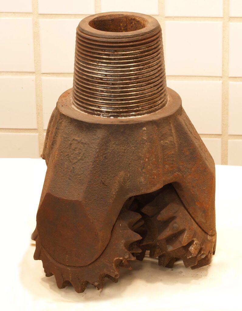
Bit selection
To select a drilling bit the following factors are considered:
- formation drillability and characteristics
- mud system in use (Types of drilling mud)
- directional implications availability
Formation Drillability: The best indication of formation drillability is bit performance (Roller cone bit performance – PDC bit performance) in nearby wells. If this information is available then the selection is made easy. Tricone bits for soft formations drill by gouging and scraping action. In soft to medium-soft formations that are not too sticky, PDC bits offer the best alternative, especially in oil-based mud. Harder formations will be drilled by using insert bits with journal bearings and gauge protection or alternatively diamond bits.
Mud systems in use: If oil-based mud is being used, it is probably to control shale problems (Check: shale Inhibitors). In this case, PDC bits will probably offer the best choice of bit. PDC bits do also work effectively in water-base mud but perform better in oil-base muds. Sealed bearing bits should be used, if the drilling fluid contains abrasive particles, to prevent premature bearing failure.
Directional Implications: Most tricone bits used for rotary drilling will exhibit some right-hand walk tendency. PDC bits on the other hand due to their symmetrical cutting action tend to drill straight ahead. If the well is planned to be drilled with tricone bits, then it is advisable to lead the well to the left and allow the natural tendency of the bits to pull the well back on course.
Hydraulics Drilling program
Once the mud has been programmed, the drilling hydraulics implications of using this mud should be considered. ‘Hydraulics’ in this case, just means looking at the mud dynamically (ECD in drilling) rather than statically.
Annular Velocity (AV): A certain minimum annular velocity is required for a given mud type to prevent cuttings slippage through the mud and to effectively lift the cuttings out of the hole to the mud treatment equipment.
Bit and hole cleaning: Drilling fluids flow in either a laminar or turbulent manner (or in a combination of these). There are two main theories concerning how much hydraulic horsepower should be expended at the bit to gain maximum cleaning efficiency. The first theory is the maximum hydraulic horsepower theory, which in practice means expending 2/3rd of the available HHP at the bit. The alternative theory is the maximum jet impact theory which in practice means expending around 50 % of the available HHP at the bit.
EVALUATION REQUIREMENTS
In this part of the drilling program, the evaluation requirements necessary to meet the well objectives should be formatted as follows:
- Drilling log requirements
- Mud logging requirements
- Coring requirements
- MWD requirements
- Electric logging requirements
- Testing requirements
WELL COST ESTIMATION IN DRILLING PROGRAM
Preparing cost estimates for the well is the final step in well planning. A properly prepared well cost may require as much engineering work as the actual well design. After the technical aspects are established, the expected time required to drill the well must be determined. The actual well cost is obtained by integrating expected drilling and completion times with the well design.
Elements of well cost:
The cost of well is based on 8 main elements which are as follows :
- Preparatory: This includes the cost of land, approach road, rig foundation, and all other civil works.
- Manpower: This is the cost incurred on the drilling crew in form of salaries, allowances, and other payments.
- Services: This includes the cost of services namely geology, geophysics, cementing, transport, workshop, production testing, catering, sea bed surveys, etc.
- Materials: This covers the cost of casing pipes, bits, wellhead, Cement additives, mud chemicals, POL ( Petroleum OiI Lubricants), and other consumable materials.
- Project overheads: The project overheads include all the other costs on drilling at the project level which are incurred towards drilling except the cost of depreciation.
- Regional and Headquarter overheads: This includes the cost incurred at the Regional and headquarters level towards drilling activity as apportioned for a given well.
- Depreciation of rig equipment: Depreciation is worked out on the straight-line method and the cost is assigned to well in proportion to the rig days taken.
- Depreciation of drill pipes: This element of well cost is based on per meter depreciation which is worked out centrally for different regions depthwise, based on the replacement cost of the pipes during the preceding year.
In the above elements, some of the costs are determined in terms of the rig days (cycle days) spent on the well, while others can be determined separately for the well itself.