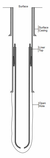
What Is Casing Liner?
A liners Casing used in drilling and completion is one of the Types of Casing or tubing string of varying length which is set with its top below the surface of the well. Liners can be cemented in place, and may include perforated pipe or well screen. We think that you might be interested in Casing Liner Hanger Setting & Cementing Procedures.
Liner installations used in a variety of formations, from the deep foothills wells of Western Canada to shallow gas wells and horizontal re-entry environments.
Types Of Casing Liner
Drilling Liners
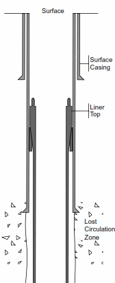
The drilling casing liners allow deeper drilling & completion operations by isolating lost circulation zones & prevent Mud Losses / Lost Circulation Problem, high-pressure intervals, and sloughing intervals. Their use will also:
- Using casing liners will reduce costs (check also drilling cost per foot). Also running a drilling liner may be more economical than running casing to the surface.
- And for sure, It will reduce casing tensile and thread requirements in deep wells.
- Another thing is that it will Improve drilling hydraulics.
Production Liners
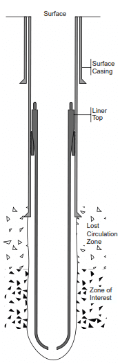
We are using a production casing liner through the producing interval of a well for various reasons:
- First, Production casing Liners are used to isolate the producing interval from drilling and completion fluid properties necessary to control uphole formations.
- Second, It is perfect for lost circulation control and well control.
- Third, we use them to reduce costs. Running a production liner to surface may be more economical than running production casing to the surface.
- To reduce the weight of the casing supported on the surface in the wellhead.
- To reduce casing tensile and thread requirements in deep wells.
- When using large diameter production tubing above the top of the liner.
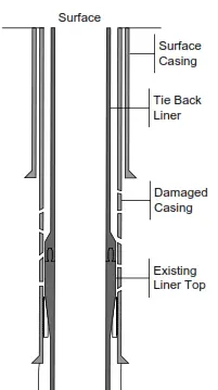
Tie Back Stub Liner
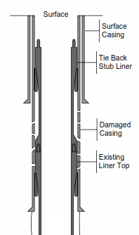
The tie-back stub liners extend existing liner tops to a point up the hole, below the wellhead. Typically, their applications are:
- First, to repair damaged or worn casing above the existing liner.
- Second, to repair an existing liner top leak.
- Third, to Provide added casing protection against corrosion or pressure anomalies.
![]()
![]()
![]() Tie Back Liner
Tie Back Liner
The tie back casing liners extend existing liners to the well head. Their applications are:
- Firstly, to repair damaged or worn casing above the existing liner.
- Secondly, to ensure casing integrity upon completion of drilling operations. Installing a tie-back casing liner at completion of drilling operations provides a casing within the well that has not been exposed to the rigours of drilling operations.
- Thirdly, to provide added casing protection against corrosion or pressure anomalies.
- Forthly, to allow individual cement placement of a liner and a tie-back liner in close tolerance conditions. Such as where a conventional dual or second stage cementing tool is not applicable due to its body diameter.
Design And Installation Considerations
The successful installation of any casing liner system should include a complete analysis of its intended application, including analysis of as many short and long term considerations as possible.
What is the application?
Identify the type of casing liners system to use by the application: drilling, production/completion, tieback stub, or tie-back. Even though final designs may vary. The type of liner system considered for installation should fall into one of these four categories.
Which liner size, weight, grade and thread type are appropriate?
Use these criteria to decide:
- Open hole size governs the amount of annular clearance in the hole section of the well and, thus, the appropriate liner size for cemented or non-cemented applications. Hole size also affects the feasibility of incorporating accessories such as annulus casing packers.
- Well geometry. Analyzing vertical-to-horizontal build rates, the length of the open hole, and anomalies in the open hole section (such as doglegs that occur due to directional drilling corrections) will help determine the appropriate liner size. In horizontal re-entry wells, an analysis of the well profile will help determine the appropriate size, weight, and thread type for the drill string design.
- Post-installation pressures. Anticipated shut-in pressures and possible stimulation pressures. Which occur after the installation of the liner are factors in selecting the appropriate liner properties.
What are the supporting casing’s size, weight, grade, and condition?
The supporting casing must be able to support the weight of the liner. While withstanding the axial force exerted against the casing by the liner slips during the installation and any potential force distributions that may occur after the liner installation. A supporting casing string that has been exposed to prolonged drilling operations may be compromised: The choice of the liner system should reflect this. The I.D. of the supporting casing will also govern the nominal O.D. of the liner. As well as the type of liner hanger equipment that you are going to use.
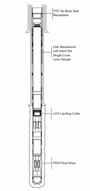
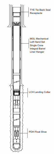
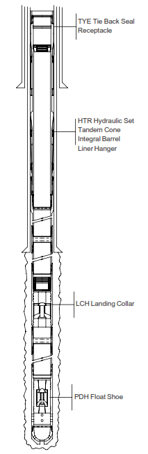
Which liner hanger system will be used?
The choice of hanger will depend on:
- Hole geometry. If, for example, a severe dogleg exists in the open hole section, it won’t be a good practice to use a mechanical set liner hanger that requires rotation of the liner to initiate the setting sequence. If the liner requires manipulation to assist placement, a specialized liner system may be required.
- Slip load distribution. The slip load distribution needed to adequately support the liner weight will determine whether a tandem cone or single cone liner hanger is preferable.
- Internal and external pressures. The liner hanger system used must be able to withstand expected internal and external pressures.
Will you plan to perform a casing liner extension in the future?
The tie-back receptacle length should be adequate to provide a seal bore long enough to allow for any elongation or contraction of the tie-back assembly. A change in the length of the tie-back string can occur in a non-cemented installation. When the tie-back string can shrink as a result of pressure and temperature changes. When cementing a tieback string, The string will shorten due to changes in pressure and temperature that occur while performing the cement job. ( please refer back to Cementing and Displacement Procedures -Single Stage & Primary Cementing Operations In Oil & Gas Wells Guide). If you are planning for a liner extension. The material strength of the tie-back receptacle must be sufficient to withstand the differential pressures that you are expecting.
Which element system is most suitable for the Casing Liner installation?
If a liner packer used to provide a secondary seal at the liner top or to repair a liner top leak, consideration must be given to the design of the element system based on the expected differential pressure, temperature, and operating environment. Typically, the liner packer set hydraulically or mechanically. Depending on variables such as hole geometry, drill pipe size (API drill pipe Specs), and well depth, one system may be more appropriate than the other. In addition, hold-down slips may be necessary to prevent upward movement of the liner.
Will the Casing liner be cemented in place?
If so, an analysis specific to cementing operations should be performed. Designing and performing a successful cemented liner job is difficult due to unique situations not typically seen in other primary cementing applications. A poor liner cement job can lead to costly remedial operations later. So, taking every effort is important to ensure success.
Any analysis specific to liner cementing should include a review of:
Float Equipment
Choosing the correct float equipment is far more critical for a liner cement job than for other primary cementing operations. Float equipment failure can make difficult and expensive cement squeezes necessary to achieve adequate hydraulic isolation in the open hole and pressure competency at the liner top.
Fluid Bypass
In addition to supporting the weight of the liner. A liner hanger system that provides maximum fluid bypass at the liner hanger is necessary to perform cementing operations. It is a must to review the bypass areas of the liner system in both the open hole section and the cased hole section of the well, and these areas should be sufficient for the anticipated flow rates, etc.
Rotation or reciprocation during cementing operations.
Pipe movement during cementing operations improves the cement bond between the open hole and the casing and it is important to incorporate it where practical on every liner cement job. In certain situations, it may be desirable to have the option to rotate or reciprocate at various points during the installation of the liner.
Casing accessories.
Are casing accessories such as annulus casing packers, stage cementing collars required to enhance cement placement operations? If so, are the accessories hydraulically or mechanically actuated? Can the accessories be incorporated in the system design without comprising the overall performance of other liner system components?
Float equipment accessories.
Using casing float equipment accessories such as centralizers, turbolizers, stand off bands, etc. When cementing a liner should be considered carefully. What float equipment accessory will work best with the liner system?
Typical Casing Liner Installations
Liners are used in a variety of well profiles. They provide unique options and flexibility not seen in conventional casing string installations, such as using coiled tubing for both the liner and the setting string.
This flexibility leads to many variations on the four basic types. No matter how unique the application design is, though. So, it will fall into one of the four basic casing liners types – drilling, production (completion), tieback stub or tieback.
Vertical Wells
Liners are regularly installed in a variety of vertical wells ranging in depth from 500 meters to 5,000 meters. The liner can range in size from 60.3-340 mm nominal O.D. Also, it may be consist of slotted casing, well screen, conventional carbon steel casing or corrosion-resistant alloy (C.R.A.) materials. Some common vertical well liner applications for shallow, medium and deep wells are described below.
Shallow Depth Vertical Wells ( Less than 1000 Meters)
Shallow depth vertical well liner installations are typically known as small diameter installations because the nominal O.D. of the liner is less than 127 mm. Commonly installed in shallow gas and oil wells as production liners, these casing liners used to provide protection to the formation from required drilling/completion fluid properties or to cover an unconsolidated interval.
The cementing of the liner can be in place and/or its setting may be on the bottom without incorporating a liner hanger. The addition of a liner top packer will be useful to provide a secondary seal at the liner top or to relieve hydrostatic pressures from the formation. Depending on the size and length of the liner, hold down slips can also incorporate to hold the liner in place.
Medium Depth Vertical Wells (1000-2000 Meters)
The nominal O.D. of liners used in medium depth vertical wells typically ranges from 114.3 mm to 139.7 mm. Most medium-depth installations produce liners installed to meet the required drilling mud properties at the zone of interest casing point. The installation of liners can be to conserve production casing costs resulting from having to set casing shallower than anticipated due to a drilling anomaly such as drilling through an aquifer, uphole sloughing conditions, or lost circulation.
In medium depth wells with an existing liner in place, tie back liners are commonly installed to repair liner top leaks or damaged casing. The tie-back liner may extend to the surface or to a point-up hole above the existing liner top. It can also be cemented in place.
As in shallow good applications, the installation & cementing of liners can be in medium depth wells to repair damaged casing in lieu of a casing patch. Depending on the conditions, the design of the liner system is to be retrievable by incorporating two or more packers. Using a liner system in medium depth vertical wells also facilitates wellbore re-entry by deepening the well.
Deep Vertical Wells ( Over 2000 Meters)
Typically, the nominal O.D. of the liners used in deep well installations ranges from 508 mm to 114.3 mm. Due to the difficulty of designing a casing program without compromising drilling hydraulics. So, most deep wells include one or more liners. These deep well installations offer design flexibility that conventional casing string installations cannot achieve.
A wide variety of applications found in deep well liner system designs, including:
- Isolating lost circulation or high-pressure intervals, or control of sloughing or plastic shale conditions.
- Protecting the production interval from exposure to drilling mud properties.
- Improving drilling hydraulics by using a large-diameter drill pipe covered by the intermediate casing in the upper section of the wellbore.
- Reducing the grade, weight and thread requirements of the casing string, and the weight of the casing supported in the wellhead.
- Increasing tension safety factors in deep wells by installing a tie-back liner with a production liner when it is desirable to run the casing to the surface. Therefore, In these installations, the support of the liner will be by the liner hanger and the support of the tie back string weight will be through wellhead.
- Repairing damaged or worn intermediate casing resulting from drilling operations.
- Reducing costs by conserving casing, equipment and related services.
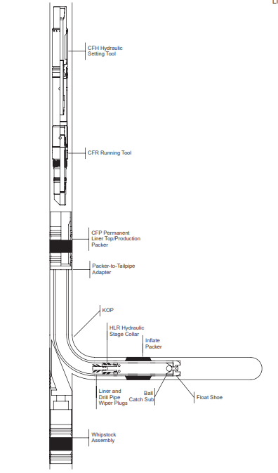
Horizontal Wells
Liner installations incorporated in short, medium and long radius horizontal wells to meet a variety of installation requirements. Therefore, Liners ranging from 30.0 meters to over 2000.0 meters in length can be installed:
- with slotted pipe for sand control in unconsolidated formations
- with annulus casing packers to provide zone isolation in the open hole section
- to provide well bore stability in the build section of the open hole
- isolate specific intervals in the horizontal section by using annulus casing packers and slotted casing. While using cement to isolate the build section of the well bore
Liner installations in horizontal wells are subject to unique operational difficulties which must be addressed before installation. These include placing the liner at the desired setting depth in wells. Where the true vertical depth relative to the length of the open hole section may be 10% or less. For these environments, new liner assemblies were developed to meet specific horizontal well conditions.
Horizontal liner installations often involve casing string designs. Which includes installing a slotted casing or well screen with the blank casing, annular casing packers or stage cementing tools in cemented and non-cemented applications. Incorporating a liner in the completion design offers the operator a variety of versatile and flexible options not seen in conventional casing string designs.
Like liners in vertical wells, cementing of liners in horizontal wells over their entire length / specific interval is a choice. We can rotate or reciprocate liner while cementing operations and can incorporate a liner top packer as a secondary seal. Whatever the design, the final liner assembly must accommodate the intended application. As with any successful liner installation, a horizontal liner installation begins with a complete analysis of the well and a careful examination of all short and long-term factors.
Horizontal Re-entry Wells
Liner installations in horizontal re-entry wells are generally small diameter liners, 114.3 mm or less. Although, the appropriate size depends on the size of the existing production casing in the well. Depending on the dimensions of the existing casing, there may be a limit in size of certain types of liner assemblies due to design and manufacturing. Because it is usually desirable to install a liner with as large a diameter as possible, using flush joint type tubulars and special clearance casing accessories is common.
Often, a liner assembly suitable for installation in a new horizontal well can also installed in a re-entry well. However, re-entry liner installations have unique operational problems not encounter in new horizontal wells, such as the need for small diameter drill strings ( Check also: Drill String Components). For example, using small diameter drill strings in certain installations may alter the ability to use conventional liner wiper plug systems when cementing. Cementing operations in these installations often involve designing and using specialized wiper plug systems. It should never be assumed that a liner assembly compatible for installation in a new horizontal well can be installed in a re-entry well.
Ref: Weathereord Casing Liners Applications Manual In Drilling & Completion