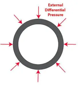
The Drill Pipe may sometimes be subjected to external pressure, which is higher than the internal pressure. This condition usually occurs during drill stem testing and may collapse the drill pipe. The differential pressure (external pressure minus internal pressure) required to produce collapse is calculated for various sizes and grades of new and used drill pipe (Api drill pipe specs). It is presented in API RP7G Tables (3), (5) and (7). Now, let’s move to the pipe collapse pressure formula.
Actual Drill Pipe Collapse Pressure Calculations
The net collapse pressure at any point on the Drill String under static conditions is:
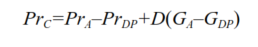
- Prc= Net Collapse Pressure on Drill Pipe.
- Pra= Surface annulus pressure.
- PrDP= Surface Drill Pipe Pressure.
- D= Depth of Interest.
- GA= Fluid Gradient in the annulus.
- GDP=Fluid Gradient in Drill Pipe.
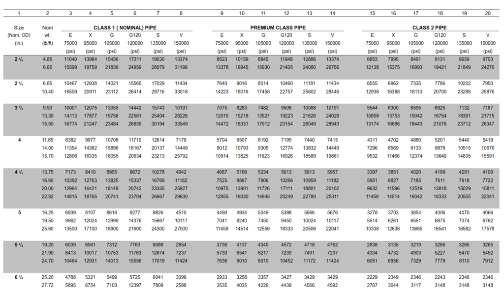
The nominal collapse pressure rating of Drill Pipe can be found below in Table 5. However, simultaneous tension reduces Drill Pipe Collapse capacity. Therefore, Collapse capacity should always be derated for the anticipated tension.
Drill Pipe Collapse Pressure Rating Formula
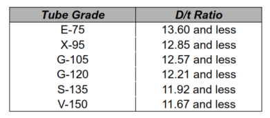
The following equations for Drill Pipe Collapse Pressure Capacity are taken from API Bulletin 5C3 to produce the values for minimum collapse pressure given in Table 5. Outside diameter is calculated assuming the same minimum wall thickness for the class being considered as before. Assume concentric OD wear to the limits of the class being considered, with the ID remaining nominal size. Which equation to use is dependent on the D/t Ratio.
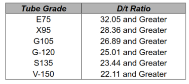
Therefore, calculate the D/t ratio for the pipe tube and use it in the following tables to determine the equation and what constants to use. For D/t ratios that satisfy the following table, “Yield-Strength Collapse” occurs.
To calculate the yield strength collapse pressure use:
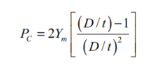
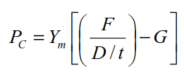
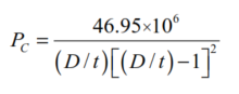
- PC= Minimum collapse pressure (psi)
- D= Tube Outside diameter (in)
- t= Tube wall thickness (in)
- Ym= Minimum tube yield strength (psi)
Plastic Range
For D/t ratios in the following ranges, the minimum collapse pressure in the plastic range applies.
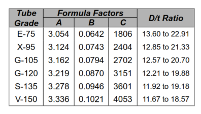
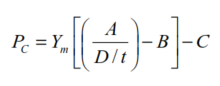
To calculate minimum collapse pressure in the plastic range use:
Between Plastic & Elastic
The D/t ratio for the transition range (between plastic and elastic) is defined below.
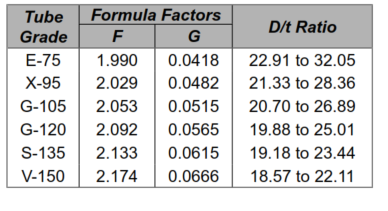
To calculate minimum collapse pressure in the transition range use:
Elastic Range
Finally, for the following D/t ratios, elastic collapse occurs.
To calculate minimum collapse pressure in the elastic range use:
Drill Pipe Collapse Pressure Capacity Table (psi)
Safety Factor
Collapse pressure ratings are presented in the drilling handbook Tables. The tabulated collapse pressure ratings must be divided by a safety factor to establish the allowable collapse pressure.
where,
- Pc = theoretical collapse rating from tables, psi
- Pac = allowable collapse pressure, psi
- S.F. = safety factor = 1.1 to 1.2
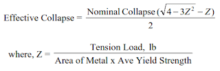
Tensile Load Effect
If the pipe is subjected to an axial tensile load, the collapse pressure ratings from the tables must be derated. The effective collapse corrected for tension load can be calculated from the equation,