Drill Collar Weight Calculation is not problematic to run. Basically, there are two methods for such calculations. In this article, we will discuss both methods and their differences. This article is a series of articles that provide a full guide for Drill String Design Calculations | Complete Guide
Buoyancy Factor Method
Number & Lengths Of Drill Collar Calculations Target & Assumptions
Before going deep in the drill collar weight calculation methods, please consider the following notes:
- Ensures that buckling is restricted to the Drill Collars and no buckling occurs in the Heavy Weight Drill Pipe (HWDP) or Drill Pipes above the Drill Collars.
- The required Collar length to provide a desired weight on the Drilling Bit can be calculated as follows,
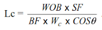
Where,
- WOB = desired weight on bit, lb
- SF= safety factor (1.1-1.15),
- BF= buoyancy factor,
- Wc= drill collar weight in air, lb/ft
- I = maximum hole angle at BHA, degrees
- This method does not consider the hydraulic forces acting on the bottom end of the Drill Collars and the shoulder areas between Drill Collars and the Heavy Weight Drill Pipe (HWDP) or Drill Pipes.
- You must understand that the Drill Collars length calculated by the previous equation is not enough to provide all the desired weight on the Drilling Bit, and, therefore, the remainder of the weight will be provided by the Heavy Weight Drill Pipe (HWDP) or Drill Pipes. Above the Drill Collars.
Drill Pipe Buckling & Neutral Point
Drill Pipe Buckling is a problem that must be avoided at all times. Heavy Weight Drill Pipe (HWDP) or Drill Pipe Buckling induces stresses in the pipe, which will cause premature pipe fatigue and failure.
Lubinski defined The Buckling Neutral Point as the point in the Drill Collar string below which the pipe is buckled (under compression) or tends to buckle, and above (Also under compression) no buckling will occur. The buckling neutral point is calculated by the following equation,
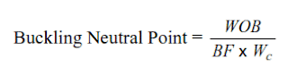
The above Equation states that no buckling occurs above the drill collars as long as the weight on the Drilling Bit does not exceed the buoyed weight of the Drill Collar.
The Drill String Axial Stress Neutral Point
Sometimes, it may be necessary to calculate the axial stress in the Drill String or locate the axial stress neutral point. All forces acting on the Drilling Bottom Hole Assembly BHA must be considered when axial stress, including the hydrostatic forces, must be determined.
The hydraulic forces result from the mud’s hydrostatic pressure and are computed by multiplying the hydrostatic pressure by the respective section area.
Axial Stresses On Heavy Weight Drill Pipe HWDP Calculations
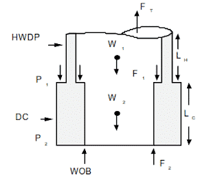
Consider the free-body diagram to determine the axial stresses in the HWDP above the drill collars.
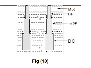
Drilling Bottom Hole Assembly BHA here consists
- Drill Collars of length LC
- Heavy Weight Drill Pipe (HWDP) of length LH.
- The hydraulic force acting on the cross-sectional area between the Drill Collar and Heavy Weight Drill Pipe (HWDP) is denoted by F1.
- The hydraulic force acting on the bottom of the Drill Collars is denoted by F2.
The Weight On Drilling Bit WOB acts on the formation, but since every action has a reaction equal in magnitude, there will be a reaction force equal to WOB acting upward on the bottom end of the Drill Collars.
- The total weights of the Heavy Weight Drill Pipe (HWDP) and Drill Collars are denoted by W1 and W2, respectively.
- The tensile force acting at the cut-off point in the Heavy Weight Drill Pipe (HWDP) is denoted by FT.
- Now, for the system to be in static equilibrium, the forces acting upward must be equal to the forces acting downward or
Ft + WOB + F2 = W1 + W2 + F1
Where
- W1 = LHWH
- W2 = LCWC
- F1 = P1(A2-A1)
- F2 = P2A2
FT = LHWH + LCWC + P1(A2-A1) – P2A2 – WOB
Where
- WH = weight in air of HWDP, lb/ft
- WC = weight in air of drill collars, lb/ft
- LH = length of HWDP, ft
- LC = length of drill collars, ft
- P1 = hydrostatic pressure at the top of drill collars, psi
- P2 = hydrostatic pressure at the bottom of drill collars, psi
- A1 = steel cross-sectional area for HWDP, in2
- A2 = steel cross-section area for drill collars, in2
- FT = tensile force, lb
It should be noted that FT is assumed to be a tensile force. If the magnitude of FT is negative, then it is a compressive force.
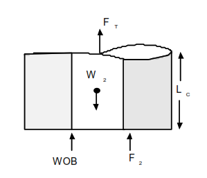
Consider the free-body diagram to determine the axial stresses in the drill collars. In this case, no hydrostatic force is acting on the top of the drill collars because there is no change in diameter (no shoulder area). Adding the forces gives,
FT + WOB + F2 = W2
FT + WOB + A2P2 = LCWC
FT= LCWC -WOB – A2P2
Drill Collar Calculation Pressure Area Method Conclusion
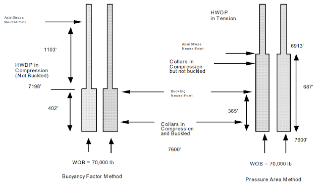
- The number of Drill Collars calculated by the Buoyancy Factor method is insufficient to provide all the weight on the Drilling Bit WOB. Some of the WOBs will be provided by the Heavy Weight Drill Pipe (HWDP) or Drill Pipe directly above the Drill Collars. For this reason, the Heavy Weight Drill Pipe (HWDP) or Drill Pipe above the Drill Collars will be in compression but not buckled. Using a Heavy Weight Drill Pipe (HWDP) or Drill Pipe in compression is acceptable as long as it is not buckled.
- The buckling neutral point is always near the top of the Drill Collars. The Drill Collars below the neutral point will have a tendency to buckle. The Drill Collars and Heavy Weight Drill Pipe (HWDP) above the neutral point will not buckle as long as the actual weight applied on the Drilling Bit while drilling does not exceed the WOB used in the calculations. If the actual WOB exceeds the WOB used in the calculations, then the number of Drill Collars must be increased. Otherwise, the Heavy Weight Drill Pipe (HWDP) or Drill Pipe above the drill collars will buckle. Heavy Weight Drill Pipe (HWDP) or Drill Pipe should never be used in a buckled condition.
Pressure Area Method For Drill Collar Calculation
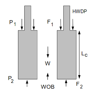
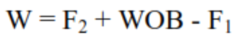
The drill collar weight calculation | The Pressure-Area Method considers all the forces acting on the Drilling Bottom Hole Assembly BHA, including the hydraulic forces. Consider the free-body diagram in the above Figure. A force balance yields,
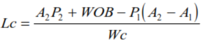
The length of the Drill Collar required to provide Weight On the Drilling Bit WOB is,
Drill Collars Weight Calculations | Buoyancy Factor Method Vs Pressure Area Method
Comparison
- It can be seen that the Drill Collar length calculated by the Pressure Area Method is almost twice that calculated by the Buoyancy Factor Method and, therefore, is enough to provide all the Weight On Drilling Bit WOB.
- For this reason, In the Pressure Area Method, only the Drill Collar is in compression while the Heavy Weight Drill Pipe HWDP is in tension.
- The buckling neutral point is the same in both cases.
- Either of the two methods can be used to calculate the length of the Drill Collar.
However, the Pressure Area Method has the following disadvantages:
- Requires more Drill Collar to keep the Heavy Weight Drill Pipe HWDP or Drill Pipes in tension. This serves no useful purpose because whether the pipe above the buckling neutral point is in tension or compression is irrelevant to fatigue damage if the pipe is not buckled.
- The need to procure, transport, maintain, inspect, and handle the extra Drill Collar increases the cost of the drilling operation (check also drilling cost per foot)
- Adding more Drill Collars reduces the available overpull.
- Adding more Drill Collars increases the weight of the Drill String and the tensile stress in the Drill Pipes at all depths. The increase in stress will increase the rate of fatigue attacks and reduce the life of the Drill Pipes.