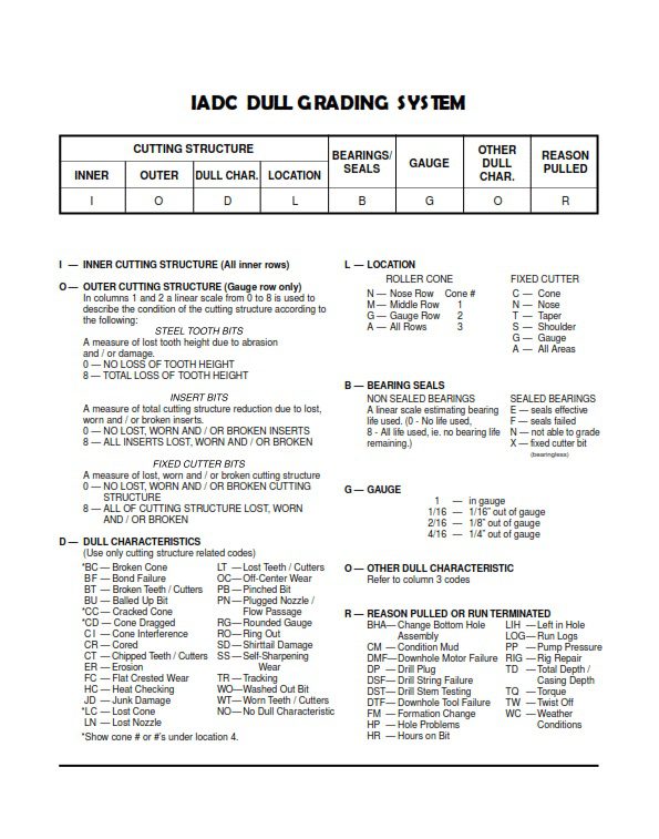
As each drill bit is pulled from the hole, we inspect and grade its physical appearance based on the wear it has sustained; this is called Bit Dull Grading. This article explains why we need to do IADC Bit Dull Grading for both PDC drill bits and TriCone Drill Bits. The IADC Bit Dull Grading system has recently been revised (1987) so that it may be applied to all types of bits. The system is based on the chart and will be described in terms of each column:
Why We Need To Do PDC & Roller Cone IADC Bit Dull Grading
The evaluation of bits is useful for the following reasons:
- To improve bit type selection
- To identify the effects of WOB, RPM, etc., which may be altered to improve the performance of the next bit
- To allow drilling personnel to improve their ability to recognize when a bit should be pulled (i.e. to correlate the performance of a bit downhole with its physical appearance on surface)
- To evaluate bit performance and help to improve their design. (Roller cone bit performance – PDC bit performance)
Bit Record
A bit record will always be kept by the operating company, drilling contractor and/or bit vendor. This bit record is used to store the following information about the bit after it has completed its run:
- The bit size type and classification
- The operating parameters
- The condition of the bit when pulled
- The performance of the bit
The IADC TriCone Drill Bit Dull Grading

Column 1 – Cutting Structure Inner Row For Tricone (I)
In the first column of IADC TriCone bit dull grading, we usually report the condition of the cutting structure on the inner 2/3 rds of the bit which is not touching the wall of the hole (Inner)
Column 2 – Cutting Structure Outer Row For Triconr (O)
In the second column of Tricone IADC bit dull grading, we usually report the condition of the cutting structure on the outer 1/3 rd of the bit for Tricone bits.
Column 1 & 2 Of IADC Tricone Bit Dull Grading

In column 1 and 2 a linear scale from 0 to 8 is used to describe the condition of the cutting structure as follows
Steel Tooth Bits : a measure of the lost tooth height.
- 0 – Indicates no loss of tooth height due to wear or breakage
- 8 – indicates total loss of tooth height due to wear or breakage
Insert Bits: a measure of total cutting structure reduction due to lost, worn and/or broken inserts
- 0 – Indicates no lost, worn and/or broken inserts
- 8 – Indicates total loss of cutting structure due to lost, worn and/or broken inserts
Example
The tooth wear of insert bits is a measure of the combined cutting structure reduction due to lost, worn and broken inserts. For example,
- If 50% of the inner inserts are broken and/or lost and the remaining inner inserts have no reduction in height, the bit is graded 4 in column 1.
- If 50% of the outer inserts are lost and the remaining inserts on the outer rows have 50% reduction in height, the bit is graded 6 in column 2.
Column 3 – IADC Tricone Bit Dull Grading Cutting Structure Dull Characteristics (D)
Report the major dull characteristics of the bit cutting structure based on the below (check Major 24 Tricone Bit Dull Grading Characteristics) :
BC— Broken Cone
BF — Bond Failure
BT — Broken Teeth / Cutters
BU— Balled Up Bit
CC— Cracked Cone
CD— Cone Dragged
CI — Cone Interference
CR— Cored
CT — Chipped Teeth / Cutters
ER— Erosion
FC — Flat Crested Wear
HC— Heat Checking
JD — Junk Damage
LC — Lost Cone
LN — Lost Nozzle
LT — Lost Teeth / Cutters
OC— Off-Center Wear
PB — Pinched Bit
PN— Plugged Nozzle / Flow Passage
RG— Rounded Gage
RO— Ring Out
SD— Shirttail Damage
SS — Self-Sharpening Wear
TR — Tracking
WO— Washed Out Bit
WT— Worn Teeth / Cutters
NO— No Dull Characteristic
Cone numbers are identified as follows:
- The number one cone contains the center-most cutting element; the spear-point on a steel tooth cone and the nose insert on a tungsten carbide insert cone. On certain TCI designs, two cones may have a nose insert. In this case, the nose insert that is offset is on the number 1 cone.
- Cones two and three follow in a clockwise orientation when viewed from above, with the bit sitting on the pin.
Column 4 – Cutting Structure Location (L) For Tricone
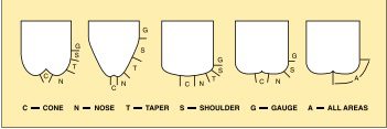
Report the location on the bit face where the major cutting-structure dulling characteristic occurs. This may be reported in the form of a letter or number code The location of dull characteristics for four fixed bit profiles is shown in table below.
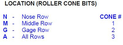
Location is defined as follows:
- Gage – Cutting elements that touch the hole wall.
- Nose – The centermost cutting element(s) of the bit.
- Middle – Cutting elements between the nose and the gage
- All – All Rows
Cone numbers are identified as follows:
- Cone 1 contains the centermost cutting element.
- Cones two and three follow in a clockwise orientation when viewed from above, with the bit sitting on the pin.
For Fixed Cutter, we can use the following:
C — Cone
N — Nose
T — Taper
S — Shoulder
G — Gauge
A — All Areas
Column 5 – Bearing Condition (B) For Tricone
Report the bearing condition of roller cone bits. Grading depends on the bit type. This space will always be marked with an ‘X’ for fixed-cutter bits.
- NON – SEALED BEARING BITS: a linear scale from 0-8 to indicate the amount of bearing life that has been used :
0 – Indicates that no bearing life has been used ( new bearing )
8 – Indicates that all of the bearing life has been used ( locked or lost )
- SEALED BEARING BITS: a letter scale to indicate the condition of the seal :
E – Indicates an effective seal
F – Indicates a failed seal
N – Indicates “not able to grade”
Column 6 – Gauge (G) For Tricone
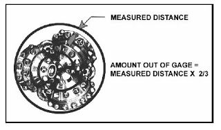
Report the bit gauge. Use the letter “I” if the bit has no gauge reduction. If the bit does have a reduction in gage, it is to be recorded in 1/16th of an inch.
The Two Thirds Rule, as used for three-cone bits, requires pulling the gage ring so it contacts two cones at their outermost points. Then multiply the distance between the outermost point of the third cone and the gage ring by 2/3 and round to the nearest 1/16 inch to get the correct diameter reduction.
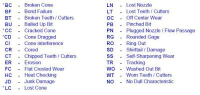
Column 7 – Remarks (O) :
Report any dulling characteristic of the bit in addition to that reported for the cutting structure in column 3. Note that this is not restricted to the cutting-structure dull characteristic. The two letter codes to be used in this column are shown below.
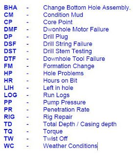
Column 8 – Reason for Pulling (R) :
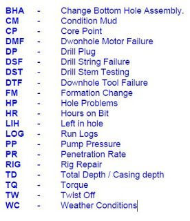
Report the reason for pulling the bit out of the hole. This may be a two or three-letter code, as shown below
- BHA — Change Bottom Hole Assembly
- CM — Condition Mud
- CP — Core Point
- DMF — Downhole Motor Failure
- DP — Drill Plug
- DSF — Drill String Failure
- DST — Drill Stem Testing
- DTF — Downhole Tool Failure
- FM — Formation Change
- HP — Hole Problems
- HR — Hours on Bit
- LIH — Left in Hole
- LOG — Run Logs
- PP — Pump Pressure
- PR — Penetration Rate
- RIG — Rig Repair
- TD — Total Depth / Casing Depth
- TQ — Torque
- TW — Twist Off
- WC — Weather Conditions
Download Summary For Tricone Bit Dull Grading
The IADC PDC Drill Bit Dull Grading
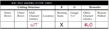
The Dull Grading System Chart adopted by IADC includes all codes needed to dull-grade roller cone bits and fixed cutter bits.
The chart describes eight drill-bit factors.
- The first four spaces describe the “Cutting Structure”.
- The fifth space (“B”) refers to “Bearing Seals” and does not apply to fixed cutter bits. This space is always marked with an “X” when grading fixed cutter bits.
- The sixth space (“G”) refers to “Gauge Measurement”
- The last two “Remarks” spaces indicate “Other Dull Characteristics” (or secondary dull characteristics) and “Reason Pulled”.
Column 1 & 2 – Inner/Outer Rows
In column 1 and 2 a linear scale from 0 to 8 is used to describe the condition of the cutting structure & indicate the amount of wear.
- In the first column of IADC bit dull grading, we usually report the condition of the cutting structure on the inner 2/3 rds radius
- In the second column of IADC bit dull grading, we usually report the condition of the cutting structure on the outer 1/3 rds radius of a fixed cutter bit.
Grading numbers increase with amount of wear, as follows:
- 0 – Indicates no loss of cutter or diamond height due to wear or breakage
- 8 – Indicates total loss of cutter or diamond height due to wear or breakage
- 4– Accordingly, “four” indicates 50% wear.
PDC cutter wear is measured on a linear scale from 1 to 8 across the diamond table, regardless of cutter shape, size, type, or exposure. Figure 1 schematically illustrates the cutter wear grading system.
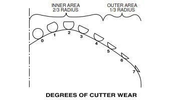
When grading a dull bit, record the average wear for each area. As shown above, 2/3 of the radius represents the “inner rows”. Grade the five cutters in this area as “two”. This is calculated by averaging the individual grades for each cutter in the area:
(4+3+2+1+0) / 5 = 2
The average wear for the “outer” area is calculated in the same manner:
(5 + 6 + 7) / 3 = 6
“Six” would be the average wear gradient for the outer area. You can now transfer this information to the IADC Dull Grading System Chart above.
NOTE: For a core bit, the centerline in Figure 1 would be the inside of the core bit ID.
Column 3 & 7- Cutting Structure Dull Characteristics (D) & Other Characteristics
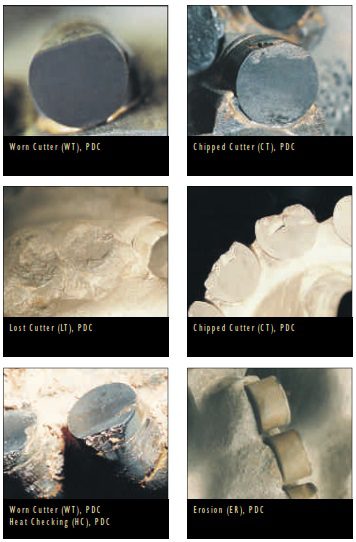
The third column is for reporting the major dull characteristics of the bit cutting structure based as below.( check also Major 14 PDC Dull Characteristics Description & Causes)
The seventh column reports any additional dull characteristics of the bit.
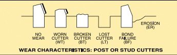
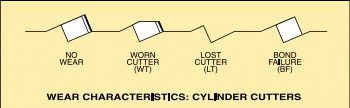
Codes for these characteristics are listed below. In general, four wear characteristics can be distinguished for fixed-cutter bits, as shown in Figures 2A and 2B. (Check: PDC Dull Characteristic Explanation and examples)
- *BC – Broken Cone
- BF – Bond Failure
- BT – PDC Broken Cutters
- BU – Balled Up
- *CC – Cracked Diamond Layer
- *CD – Cone Dragged
- CI – Cone Interference
- CR – Cored
- CT – Chipped Teeth/Cutters For PDC
- ER – PDC Erosion
- FC – Flat Crested Wear
- HC – PDC Heat Checking
- JD – Junk Damage
- LC – Lost Cone
- LN – Lost Nozzle
- LT – PDC Lost Cutters
- NO – No Major/Other Dull Characteristics
- NR – Not Rerunnable
- OC – Off-Center Wear
- PB – Pinched Bit
- PN – Plugged Nozzle/
- Flow Passage
- RG – Rounded Gauge
- RO – PDC Ring Out
- RR – Rerunnable
- SD – Shirttail Damage
- SS – Self Sharpening Wear
- TR – Tracking
- WO – Washed Out Bit
- WT – PDC Worn Cutters
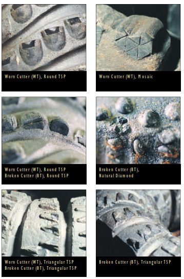
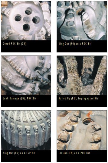
Examples Of The PDC Dull Characteristics
Column 4 – Cutting Structure Location (L)
The “Location” column indicates the location of the primary “Dull Characteristics” reported in the third column. Figure 3 shows four possible fixed cutter bit profiles, along with the codes used to identify commonly referred-to locations on the bit. One or more of these codes are used to indicate the location of the dull characteristic(s) noted.
Column 5 – Bearing Condition (B) For PDC
This column is used only for Tricone bit dull grading. Therefore, it will always be marked “X” when grading fixed cutter PDC bits.
Column 6 – Gauge (G) For PDC
The “Gauge (G)” column reports the condition of the bit gauge. Record an “I” here if the bit is still in gauge. Otherwise, the amount the bit is undergauge is recorded to the nearest /16”. For specific undergauge markings, see Figure 4.
- I: In Gauge
- 1/16 : Under-gauge up to1 /16”
- 2/16: Under-gauge 1 /16” to 1/8″
- 3/16 : Under-gauge 1/8” to 3/16”
- 4/16 : Under-gauge 3/16” to 1/4″
Column 8 – Reason for Pulling (R) For PDC
The last column on the IADC Dull Grading System Chart reports the reason the bit was pulled. A list of codes is shown below.