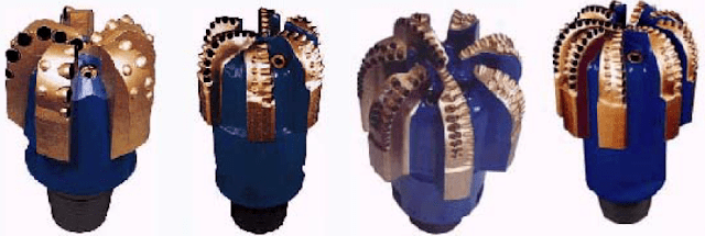
PDC drill bit design determines how a fixed-cutter bit shears rock, handles torque and impact, removes cuttings, and maintains hole gauge. A PDC (polycrystalline diamond compact) bit uses synthetic-diamond cutters bonded to hard substrates and mounted on steel or matrix-body blades. Its performance depends on the combined design of cutter size and density, back/side rake, blade and bit profiles, gauge protection, and drilling-fluid hydraulics. Choose a bit for the specific formation and operating envelope, not from an assumed universal advantage over roller-cone bits. For the economic comparison, use drilling cost per foot and the bit selection process.
PDC bits belong to the fixed-cutter family of drilling tools. To understand how they differ from roller-cone, natural-diamond, and TSP bits, see our comparison of drilling bit types.
PDC Drill Bit Design: Quick Answer and Main Components
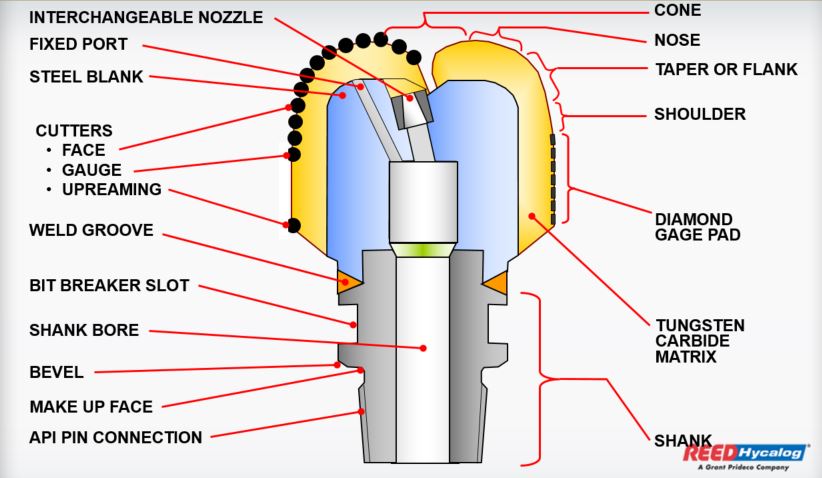
What are the main components of a PDC drill bit? The principal components are the steel or matrix body, blades, polycrystalline-diamond cutters, cutter pockets, nozzles and waterways, junk slots, gauge pads and threaded connection. Their arrangement sets bit aggressiveness, stability, cleaning, durability and directional response. This article focuses on how each design choice changes drilling performance, rather than duplicating the broader types of drilling bits comparison.
| PDC design variable | Primary effect | What the engineer should verify |
|---|---|---|
| Cutter grade, size and shape | Shearing efficiency; impact, abrasion and thermal resistance | Offset dull grades, lithology, cutter damage mechanisms |
| Number and distribution of cutters | Depth of cut per cutter, loading, torque and bit life | ROP-versus-durability target and regional wear |
| Back and side rake | Aggressiveness, cutting force and chip movement | Torque limits, impact conditions and cutter support |
| Blade profile and gauge | Stability, steerability, junk-slot clearance | BHA/RSS design, trajectory and hole gauge requirements |
| Nozzle TFA and waterways | Bit-face cleaning, cutter cooling and hydraulic pressure drop | Pump rate, standpipe pressure and cuttings transport |
PDC Drill Bit Design Features
The main PDC drill bit components and design decisions are summarized below. Cutter durability, mechanical stability, hydraulic cleaning, and drilling economics must be assessed together.
- Unlike roller-cone bits, a conventional PDC fixed-cutter bit has no cone bearings or moving cones; however, it can still fail through cutter damage, gauge wear, body erosion, or vibration.
- PDC cutters primarily shear rock. Shearing can be more energy-efficient than indentation and crushing in suitable formations, but the advantage depends on rock properties and cutting geometry.
- The required WOB is determined by cutter engagement, formation strength, bit aggressiveness and the drillstring/BHA limits. A PDC bit does not have one universally low WOB requirement.
- Fixed-cutter designs can suit rotary, motor, rotary-steerable or turbine systems when the cutter layout, bit stability, hydraulics and permitted operating speeds are compatible.

Field performance must feed back into the design. Compare offset runs using footage, ROP, torque, hydraulic parameters, vibration, dull grading and total cost rather than selecting only by the best single run.
Manufacturers arrange PDC cutters over the cone, nose, shoulder and gauge regions, with blade profiles and fluid courses designed to balance cutter loading, rock removal, cleaning and directional response. Although a PDC bit may deliver long runs and high ROP in a suitable interval, no fixed multiplier over roller-cone performance applies to every formation. Use calibrated offset data and a documented cost-per-foot comparison instead of applying historical case figures as a general rule.
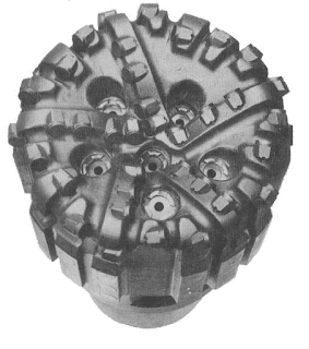
PDC bit bodies are commonly machined steel or tungsten-carbide-rich matrix bonded to a steel shank. Steel provides toughness, design flexibility and repair potential but generally needs abrasion and erosion protection; matrix provides strong erosion resistance but is usually more brittle. The quality of cutter pockets, brazing, blade support and hydraulics can matter more than choosing one PDC bit body material in isolation.
A conventional PDC cutter has a generally cylindrical substrate and a diamond cutting face, but modern cutter families also include shaped or nonplanar cutting elements. Geometry should be selected for the required cutting action, impact resistance, temperature exposure and formation response; not all cutter shapes are interchangeable.
Where PDC Drill Bits Work Best — and Where Design Matters Most
- Long relatively uniform shale, carbonate or other PDC-drillable intervals can favour continuous shearing and long bit runs, provided the mud system controls balling and the cutter grade manages wear.
- Hard, abrasive and interbedded formations can damage poorly matched cutters; they do not categorically exclude PDC. Consider abrasion-resistant cutters, bit stability, cutter density and offset dull-grade evidence for the specific interval.
- Transitions between soft and hard layers can impose impact loads and torque fluctuations. Backup cutters, tougher grades, depth-of-cut control or hybrid cutter architectures may be considered, depending on the engineering objective. A backup-cutter PDC bit should not automatically be called a hybrid roller-cone/PDC bit.
- Increased cutter redundancy or specialized cutting elements may distribute load and preserve gauge in abrasive stringers, but the actual benefit should be demonstrated through bit design, modelling and field results.
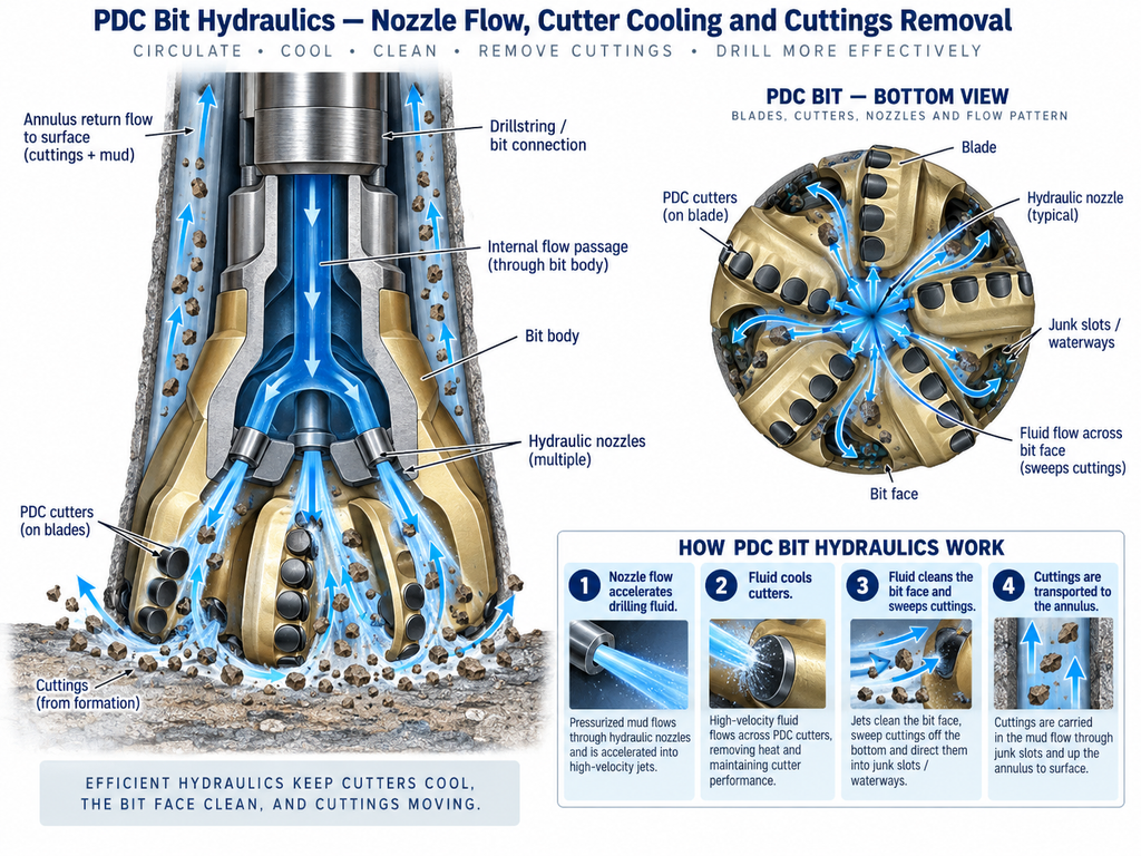
- Hydraulic nozzles and waterways must clear cuttings from the bit face and cool the cutters. Restricted flow paths may lead to cuttings recirculation, bit balling and thermal damage even when the diamond grade is advanced.
- Salt and plastic or swelling formations may require additional hole-clearance measures, specialized profiles or a suitable hole-opening system. The choice depends on salt movement, casing clearance, trajectory and sticking risk; eccentric designs are not a universal remedy. Review stuck-pipe mechanisms in the actual well plan.
- Motor, turbine and rotary-steerable runs place different demands on allowable RPM, torque, side force, hydraulics and steerability. Coordinate the bit design with the BHA and the manufacturer’s operating limits rather than prescribing a universal profile.
PDC Drill Bit Design & Components
A useful PDC bit design review covers the following linked decisions:
- Bit-body material and blade support (steel versus matrix)
- Cutter substrate, diamond-table grade, interface and damage resistance
- Cutter size, density and regional placement across the bit face
- Back rake, side rake, edge preparation and cutter shape
- Blade count, profile, gauge length and hydraulic-nozzle layout
For an overview of companies producing roller-cone and fixed-cutter designs, see our drilling bit manufacturers list.
PDC Drill Bit Body
PDC bit bodies generally fall into two common constructions. Neither body type is always better:
- Steel body: commonly machined from steel with integral blades. It offers comparatively high toughness, design flexibility and repair options. Wear coatings and hardfacing help protect exposed surfaces. Local cutter support and pocket geometry, rather than a blanket claim about steel impact resistance, influence cutter breakage.
- Matrix body: typically produced using a tungsten-carbide-rich composite formed around a steel mandrel or shank. It generally resists erosion and abrasion well, but its brittle response can constrain blade design. Balling depends on formation adhesion, fluid chemistry, blade clearance and hydraulic cleaning—not body material alone.
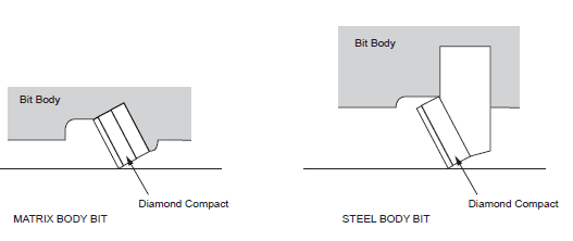
Modern steel and matrix bits overlap in application. Evaluate erosion, torsional and impact loading, blade height, cutter support, repairability, manufacturing constraints and total run economics rather than selecting from the body label alone.
Manufacturers continue to refine matrix composites, cutter retention, brazed interfaces and blade geometry. Published percentage improvements must be tied to a named design and test method; generalized claims of fixed gains in tensile strength or braze strength cannot support a bit-selection decision.
PDC Cutter Materials and Diamond Tables
A conventional PDC cutter consists of a polycrystalline synthetic-diamond table bonded to a cemented tungsten-carbide substrate. High-pressure/high-temperature sintering creates the diamond structure; cobalt or related metallic binders may facilitate processing. Cutter performance depends on diamond microstructure, interfacial bond design, residual stresses and thermal/impact exposure. The process cannot accurately be defined by one universal temperature or pressure for every manufacturer.
Please visit the PDC Bit Cutters Material article for more detailed information.
Cutter Density and Regional Placement
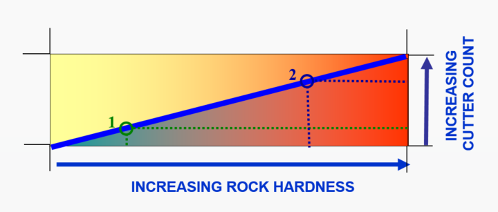
Cutter density controls how the available bit load is shared. Fewer or more exposed cutters can make a bit more aggressive and increase instantaneous depth of cut, but may increase per-cutter force, torque fluctuations and damage risk. More cutters can distribute load and improve durability, while also changing cleaning space and achievable penetration. Designers vary density by radial region, not only by the hardness label of a formation.
PDC Cutter Size Selection
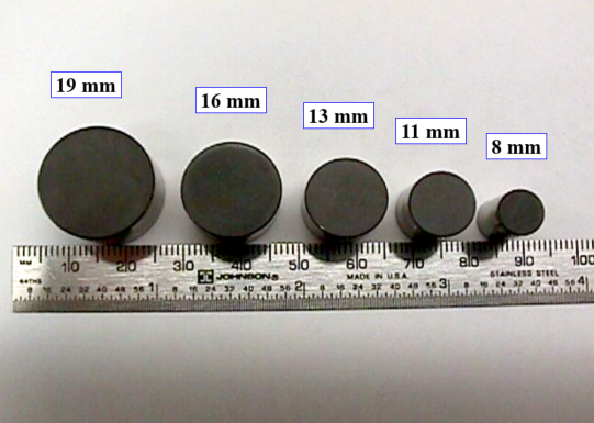
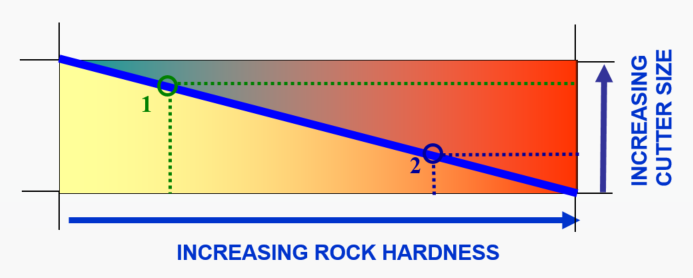
Cutter diameter influences cutting-edge length, available cutter volume, force distribution, placement density and repairability. Larger cutters can suit aggressive soft-formation designs; smaller cutters can allow closer spacing and specific durable layouts. Common catalog sizes are not a universal limit, and modern shaped-cutters may use other dimensions. Match size and grade to formation, anticipated impact and bit-body geometry.
PDC Cutter Back Rake and Side Rake
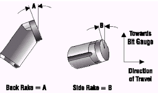
Cutter orientation is usually described by back rake and side rake angles (rather than “rack”). Both depend on local bit-face geometry; a dimension that suits the cone does not necessarily suit the shoulder and gauge.
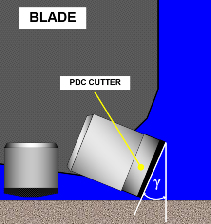
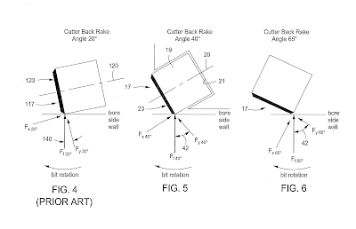
- Back rake describes the cutter-face inclination relative to the reference plane normal to the local rock surface. In broadly similar conditions, a smaller back-rake angle often yields a more aggressive cutter and greater depth of cut, but can increase torque and impact exposure. Greater negative back rake may improve robustness and lower aggressiveness, at the cost of increased cutting forces. No single 15°–45° range fits all commercial designs or all radial positions; use manufacturer data and appropriate downhole mechanics.
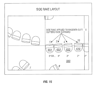
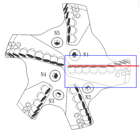
- Side rake is the lateral angular orientation of the cutting face. It alters the direction of chip flow and cutting forces; jet placement, watercourses and mud properties remain essential to effective removal of cuttings from the bit face.
PDC Cutter Shapes and Edge Design
Cylindrical PDC compacts are widely used, but engineered cutting elements can also have chamfered, ridged, conical or other shaped contact geometries. The choice changes stress concentration, cutter engagement, impact tolerance and cleaning requirements. Nonplanar interfaces between the diamond table and substrate can help manage interfacial stresses and delamination.
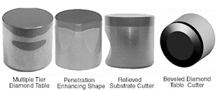
Some cutters use engineered diamond-table interfaces or multiple functional cutting regions to improve wear management. Such configurations must be matched to the application; manufacturers should document the cutter-grade specification, damage mechanisms and field validation.
Specialized cutting elements can change how the bit fractures or shears carbonate, abrasive or interbedded rock. A harder or more aggressive shape may reduce required weight on bit (WOB) at a target depth of cut, but it can also alter torque, vibration and cutter life. Treat claims of lower WOB or faster ROP as application-specific.
Cutter Exposure
Cutter exposure is the projection of the cutting edge beyond its supporting blade or bit surface. It affects available depth of cut, face clearance and rock-contact forces. Excessive unsupported projection may increase bending and impact vulnerability, whereas insufficient clearance can restrict chip removal.
Choose cutter exposure together with blade geometry and hydraulic design: more opening may improve chip passage in sticky formations, while adequate pocket support is needed to resist impact and preserve the diamond-table bond.
Blade Count and Cutting Structure Density
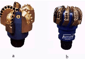
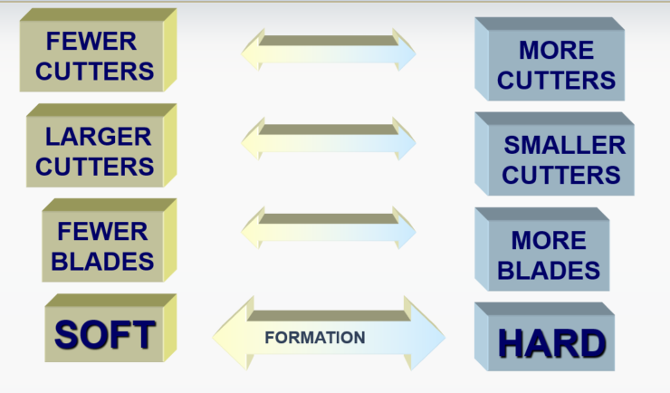
Soft-formation PDC bits often use fewer, taller blades with more open junk slots, whereas a harder or more abrasive application may benefit from more blades or cutter redundancy. These are tendencies, not absolute design rules; stability, directional requirements and bit-face cleaning may justify different layouts.
- Soft or sticky formations: larger junk slots and effective hydraulics can reduce the risk of bit balling when high cuttings volumes are generated.
- Hard or abrasive formations: designers may increase cutter support and density or choose more durable cutter geometries while managing the higher torque, impact and cooling requirements.
Blade Height and Junk-Slot Clearance
Blade height controls junk-slot flow area and the support available beneath the cutters. Tall blades may improve clearance and cuttings transport in high-ROP, sticky formations; shorter or more heavily supported designs may be desirable where impact, abrasive wear or body strength governs. Steel-body construction can accommodate some taller or more open blade architectures, but design limits depend on the product.
Blade Geometry and Bit Stability
Blade layouts range from relatively straight to highly curved, with primary and backup cutters positioned to manage radial load distribution and bottomhole coverage. Curvature is only one stability variable: bit profile, cutter aggressiveness, depth-of-cut control, gauge length and BHA dynamics must also be considered.
PDC Bit Profile: Cone, Nose, Shoulder and Gauge
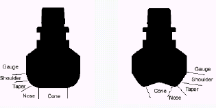
The bit profile distributes cutters across the cone, nose, shoulder and gauge and influences rock-contact length, steering response, cutter wear and flow distribution. Two broad geometric examples are:
Deep/conical profile: can provide space for additional inner cutters and stability features, but its performance depends on the cone angle, shoulder layout, formation and directional application.
Shallow/flatter profile: changes cutter engagement and bit response; it can aid steerability in selected systems but is not automatically faster or easier to clean than a deep profile.
Profile selection should consider nose/shoulder wear concentration, available cutter density, hole quality, steerability and compatibility with the BHA. Do not infer stability from cone depth alone.
Bit Length, Gauge Length and Steerability
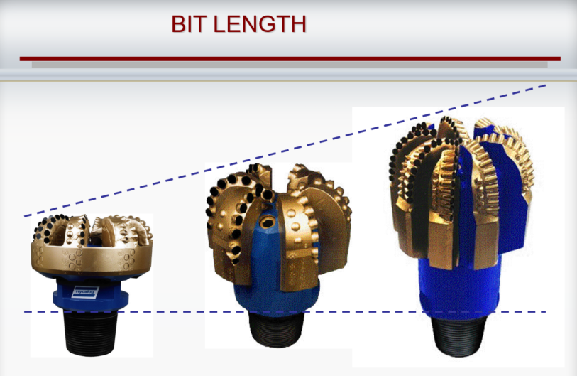
Bit length and effective gauge length influence steering response, side-wall engagement and the tendency to build, hold or drop inclination. Shorter or more compact assemblies can improve steering authority in some sidetrack operations, but directional performance also depends on motor/RSS design, bit profile and contact loads. See sidetracking considerations.
Figures that compare directional bit designs should be read as examples of geometry, not as universal predictions of dogleg severity or directional performance.
Cutters near the shoulder and gauge travel farther in one revolution than cutters near the centre, so they experience different cutting velocities and wear loads. Excessive gauge wear can produce an undergauge hole, cause tight-hole symptoms and complicate the next bit run or casing operation. Compare offset dull grading and the actual hole-condition evidence (PDC dull characteristics and causes guide).
Gauge protection can include hardfacing, additional cutters and suitably designed gauge pads. The design should maintain a usable borehole diameter while balancing side force, steerability, gauge length and susceptibility to differential or mechanical sticking.
Extended gauge sections are possible on fixed-cutter bits, but longer gauge contact can restrict directional response. Select the gauge geometry for the directional program and hole condition rather than maximizing length automatically.
Hydraulic Nozzles, Waterways and Bit-Face Cleaning
A PDC bit may shear rock faster than cuttings can be transported away from the bit face. Therefore, bit hydraulics are a cutting-performance and reliability design variable, not merely a nozzle-size specification. Nozzle positions and internal watercourses should minimize stagnant zones, chip recirculation and local heating at the cutter edges. The total-flow-area calculation is a geometry input; hydraulic design also requires pump capability, pressure losses and the drilling fluid’s properties.
For round nozzles, total flow area (TFA) = Σ[π × d² / 4], where each nozzle diameter d is expressed in inches and TFA is in square inches. A bit with three identical 12/32-in. nozzles has TFA = 3 × π × (0.375)² / 4 ≈ 0.331 in². This numerical example does not establish an acceptable jet impact, pressure drop or cleaning efficiency; those require the full hydraulic model and manufacturer limits. See the nozzle TFA calculation guide.
PDC Bit Design Trade-Offs: A Practical Review Table
| Observed design choice | Potential benefit | Trade-off or limitation |
|---|---|---|
| Fewer, aggressive cutters | Higher depth of cut for a given loading condition | Higher local load/torque; impact or cutter damage may limit life |
| More cutters or backup rows | Lower loading on individual cutting elements; redundancy | Less junk-slot area or higher rubbing losses if not optimized |
| More protective back rake | Reduced aggressiveness and possible edge durability benefit | More cutting force can be required for equivalent penetration |
| Tall blades and open slots | Better flow area for cuttings removal | Need adequate blade strength, erosion resistance and cutter support |
| Longer gauge contact | More lateral engagement and possible tracking stability | May restrict steerability or increase contact loads in doglegs |
| Higher nozzle velocity | Can improve local cleaning when optimized | Pressure drop and erosion may exceed system constraints |
Use Offset Runs, Dull Grading and Drilling Economics to Verify the Design
Before choosing a PDC bit, assemble the offset formation tops, compressive-strength indicators, drilling-fluid data, RPM, WOB, torque, flow rate, standpipe pressure, ROP, footage and run hours. Review bit photographs and IADC dull grading for cutting-structure wear, impact damage, balling and gauge condition. Combine these observations with PDC bit performance trends and total cost per foot.
Diagnostic example: if torque becomes erratic while ROP falls in sticky shale, do not assume the answer is to install more cutters. Poor bit-face cleaning, bit balling, formation changes, cutter wear and drillstring dysfunction can produce overlapping symptoms. Check flow/pressure trends, shaker returns, vibration and bit-condition evidence before attributing the problem to bit design.
| Field observation | Possible design or operating explanation | Evidence to examine |
|---|---|---|
| ROP falls steadily over the interval | Progressive cutter wear, formation hardening or insufficient depth of cut | WOB/RPM/torque trend, lithology, dull grade |
| Torque spikes or stick-slip | Over-aggressive cutting, torsional dysfunction or changing rock interface | Downhole vibration if available, surface torque, depth-of-cut response |
| Cuttings loading or sticky face | Insufficient jet placement/cleaning, mud chemistry or bit balling | TFA/flow model, mud properties, returns and bit photographs |
| Undergauge hole or gauge damage | Shoulder/gauge wear, abrasive formation and contact-load concentration | Caliper/hole condition, gauge dull assessment, BHA geometry |
PDC Drill Bit Design: Questions Engineers Commonly Ask
Are more PDC cutters always better?
No. Increasing cutter density can spread load and extend durability in some intervals, but it can also change torque, cleaning clearance, aggressiveness and ROP. Regional cutter placement and the expected failure mode matter more than the absolute count.
Why are steel and matrix PDC bit bodies both used?
Steel tends to offer toughness, manufacturing flexibility and repairability; tungsten-carbide matrix provides strong erosion and abrasion resistance but is generally more brittle. The application, blade support and hydraulic geometry determine the appropriate design.
How does back rake affect PDC bit performance?
Back rake changes the orientation of the cutter edge relative to the rock. In broadly comparable situations, smaller back rake can give a more aggressive cut and higher torque or impact exposure, whereas more protective rake can improve robustness but may require greater cutting force.
Which figures are essential before selecting a PDC bit?
Review formation and offset-well conditions, cutter wear and dull-grade records, planned WOB/RPM/flow, directional/BHA needs, hydraulic limits, vibration response and total expected section cost. Manufacturer modelling and an operating envelope are preferable to a single historic ROP comparison.
Technical References and Data Limitations
Primary engineering source: W. H. Wamsley Jr. and Robert Ford, “Introduction to Roller-Cone and Polycrystalline Diamond Drill Bits,” Chapter 5 in SPE Petroleum Engineering Handbook, Volume II: Drilling Engineering (2006), OnePetro/SPE book chapter. This chapter provides the foundations for cutter density, back rake, bit profile, cleaning and dull grading.
Supporting references: R. F. Mitchell and S. Z. Miska, Fundamentals of Drilling Engineering (uploaded technical library); SLB Oilfield Review: Defining Bits for the PDC cutter/body/flow-path overview; and the IADC Bit and BHA Dull Grading Manual announcement (2026) for current industry dull-grade documentation.
Scope: Tool and cutter designs evolve. All examples in this article are educational, and operating limits, cutter-grade claims, bit hydraulics and drilling parameters must be checked against the installed product, well conditions, and manufacturer documentation.
PDC Bit Design Selection: Engineering Summary
A successful PDC bit design is a balanced compromise among rock-cutting efficiency, cutter durability, hydraulics, directional stability, and run economics. The following points summarize the selection logic:
- Operating speed: select cutter grade, profile, exposure and density for the expected RPM range, WOB, torque, drive system and vibration environment. Turbine, motor, RSS and conventional rotary applications require system-specific checks.
- Hydraulic cleaning: evaluate bit nozzles and fluid courses against pump capability, desired bit pressure drop, thermal management, rock cuttings and the drilling-fluid system. Neither water-based nor oil-based mud alone dictates a universal nozzle arrangement.
- Soft-formation tendency: fewer blades, larger exposed cutters and open junk slots can be appropriate where cutting efficiency and chip evacuation dominate.
- Hard/abrasive tendency: more support, cutter redundancy and abrasion resistance may be important, but the final design should be chosen using expected lithology, impact, offset performance and dull-grade evidence.