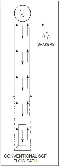
In subsea situations, a pressure loss exists when circulating through the choke line due to the friction losses in the extended choke line running up from the BOP. This pressure loss is not accounted for in normal Slow Circulating Rate (SCR) measurements, which are taken while circulating up the marine riser (see Fig 1). In this article, we shall discuss chock line friction loss definition and measurement methods.
Choke Line Friction Loss Problems
If the normal method of bringing mud pumps to kill speed is followed (that is, choke manifold pressure maintained equal to SICP until kill rate is achieved), bottom hole pressure will be increased by an amount equal to this choke line friction loss (CLFL). This excess pressure can result in seriously lost circulation in drilling operations problems during the killing operations.
Since fracture gradients generally decrease with increased water depth, correct handling of the CLFL becomes more critical as water depth increases. Beyond approximately 500 feet of water depth, it should always be considered while planning well control operations.
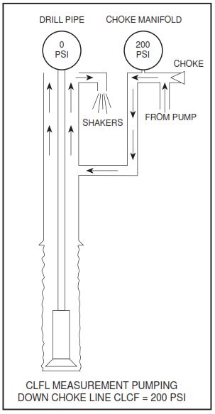
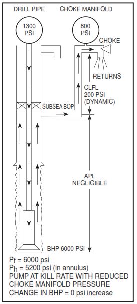
It is possible to measure choke line friction loss while taking SCR’s. One simple way to do this is to pump down the choke line at reduced pump rates (taking returns up the open marine riser as is shown in Figure 1.20) and record the pressure reading on the choke manifold gauge.
It is fundamental to all standard methods of well control to maintain constant bottom hole pressure (BHP) throughout kill operations. To accomplish this a method must be used to keep total applied casing pressures relatively constant while bringing the mud pump to kill rate.
In the absence of significant CLFL (surface stacks or shallow water), the method used is to merely keep choke manifold pressure equal to SICP until the pump is up to speed.
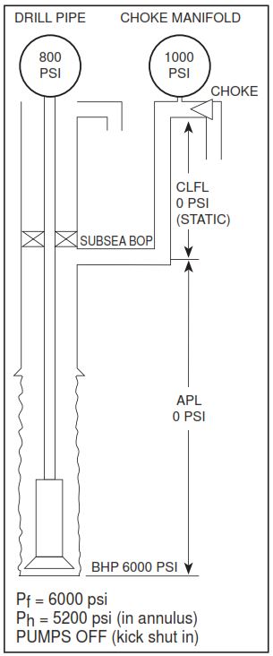
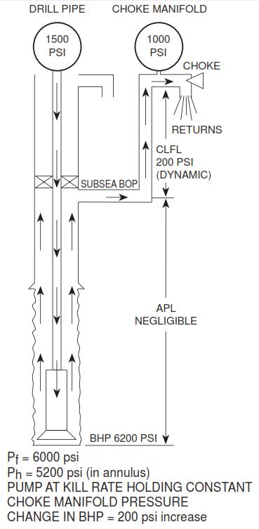
But when choke line friction loss CLFL exists, total applied casing pressure varies from SICP at pump start-up to SICP + CLFL with the pump at kill rate, if the above method were used. This would cause bottom hole pressure to increase by an amount equal to CLFL, as shown in Figures 3 and 4.
Solving Choke Line Friction Loss Problem
If SICP is Greater than CLFL
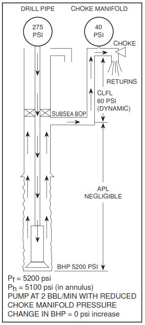
To eliminate this problem, two methods exist. First, by reducing choke manifold pressure by an amount equal to a known CLFL (adjusting choke manifold pressure to SICP -CLFL), the effect of the CLFL is negated. This is accomplished by reducing the original SICP by the amount of choke line friction loss CLFL while bringing the pumps to speed (see Figure 5). Once kill rate pressure has been established, the choke operator switches over to the drill pipe gauge and follows the drill pipe pressure graph in the usual way.
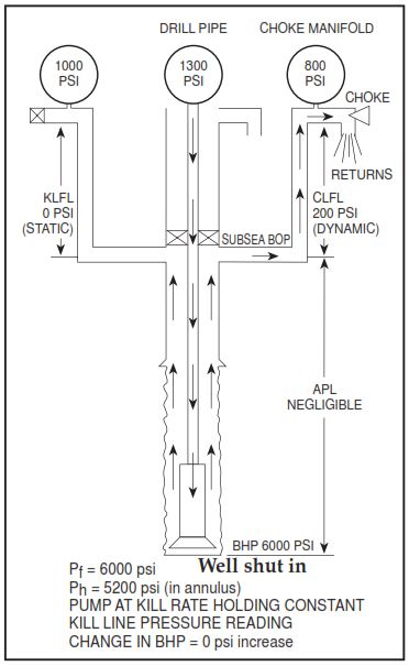
Or secondly, given a choke manifold configuration with separate pressure gauges for the choke and kill lines, it is possible to utilize the kill line (shut off down-stream of the gauge outlet to prevent flow, thus eliminating friction) as a pressure connection to a point upstream of any potential CLFL (known or unknown). This is shown in Figure 6. If the kill line gauge in this instance is kept constant while bringing the pump to speed, the effect of CLFL is eliminated.
Note the advantages of the second method:
- The gauge reading choke manifold pressure will show a decrease after pump is up to speed. The amount of this decrease is equal to the CLFL.
- No precalculated or pre-measured CLFL information is required.
- The kill line gauge can be subsequently used like the choke manifold pressure gauge on a surface stack for the purposes of altering pump rates or problem analysis.
NOTE: If the second method of handling the CLFL situation is preferred, it would be advisable to rig a remote kill line pressure gauge which could be seen by the choke operator.
It is extremely important to note that regardless of which method is used, they both accomplish the goal of maintaining constant bottom hole pressure equal to formation pressure, just as would be the case were CLFL absent. This is done without the need to alter any calculations on the kick sheet (check also: kick warning signs). Thus initial and final circulating pressures, which are read on the drill pipe gauge, are unaffected by CLFL. CLFL is recorded on the Kick Sheet for convenience only – it is not used in kick sheet calculations.
If SICP is Lower than CLFL
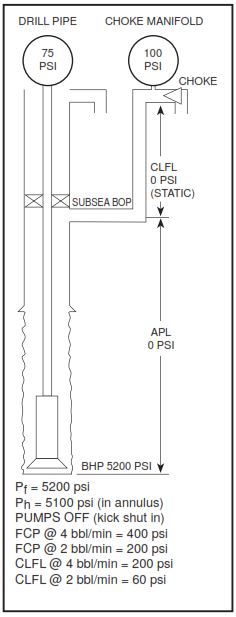
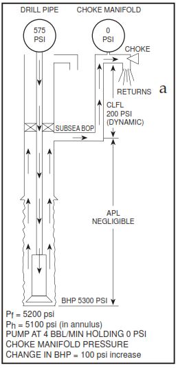
Several additional points should be made about choke line friction loss CLFL. It should be noted that it will only be possible to use the above-recommended methods when SICP is greater than CLFL. If this is not true, it will be unavoidable to apply excess pressure to the bottom of the hole using standard well control procedures. Also, as kill mud comes up the annulus, the total applied casing pressure needed to maintain constant bottom hole pressure will eventually drop below CLFL. After this point, drill pipe pressures will exceed planned Final Circulating Pressure in spite of having the choke wide open with no choke manifold backpressure.
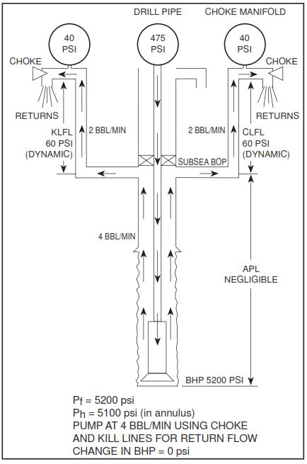
These situations can be mitigated by use of unusually slow pumping rates or by taking returns up choke and kill lines simultaneously. Figures 7 – 10 illustrate this problem and methods of dealing with it. They show an example in which a static SICP of 100 psi is reduced while pumping as a result of the increase in back pressure created in circulating up the choke line, by itself or choke and kill lines together.
Ref: Aberdeen Drilling Well Control Manual