The purpose of the marine drilling riser is to extend the offshore well from the top of the blow-out preventer package at the sea bed to the diverter beneath the rotary table. Thus, Drilling fluid returns are obtained, and tools can be easily guided into the well bore.
Choosing the appropriate marine riser size based on the BOP stack size is crucial. For example, we use a 21″ OD marine riser for a one-stack BOP system of 18 3/4″. Low annular velocities due to the relatively large riser diameter concerning the hole size drilled gives concern to accumulation of cuttings inside the riser. Good drilling fluid properties can provide adequate carrying capacity. This carrying capacity will bring the cuttings to the surface, but this can be improved with a booster line.
A booster line is an additional pipe we run with the riser, entering the riser just above the BOP stack. The drilling fluid circulation can continue through this line to increase the annular velocity inside the marine riser. Therefore, it will improve cutting removal. Note that not all drilling rig types are equipped with a booster line.
A floating drilling offshore rig has six degrees of freedom of motion: heave, surge, sway, yaw, roll, and pitch. A riser similar to that used on platforms would be sufficient without these motions. However, floating operations require additional equipment to allow for a certain degree of freedom of vessel movement. This equipment includes:
- Telescoping joint: To compensate for vessel heave due to waves and tide.
- Upper ball/flex joint: To compensate for yaw, roll, and pitch motions.
- Lower ball/flex joint: To compensate for surge and sway motions.
Drilling Riser Working Principle
At the top of the riser, mounted immediately below the rotary table, is the diverter package, which provides a means of packing off the annulus around the drill string. This facility is meant to divert small amounts of gas, e.g., gas trapped inside the BOP after circulating out a well kick, under controlled conditions and not to be used as a diverter for shallow gas. If you want to effectively manage shallow gas sub-sea, many suggest either drilling blindly or using a sub-sea diverter..
Running and retrieving the sub-sea BOP package and the marine riser together is standard practice. However, we can disconnect the marine riser from the BOP package utilizing a hydraulic latch at the lower end of the riser. This connector hydraulic release is achievable in case an emergency disconnect of the riser is essential, leaving the well secured with the BOPs. Installing a hydraulically operated valve or valves may be mandatory immediately above the connector. Therefore, this will allow rapid flooding of the riser with seawater in case of losses to avoid riser collapse.
The following factors are essential when considering the suitability of a particular offshore drilling riser system:
- Water depth.
- Expected environmental conditions, particularly sea state.
- Performance of vessel station keeping system.
- Expected maximum drilling fluid density that we can use.
- The tensioning capability of the vessel
- Attachment of kill, choke, and booster lines
- Ease of handling and makeup (connections).
The remainder of this Topic will give a more detailed overview of the different components of the marine riser, together with their function, operating limitations, and examples of components from different manufacturers.
The Marine Drilling Riser
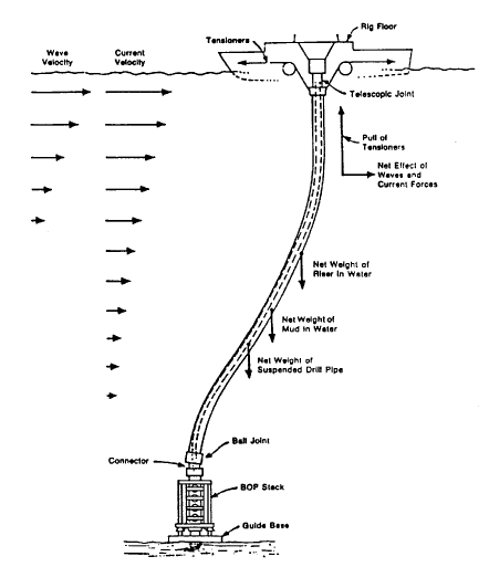
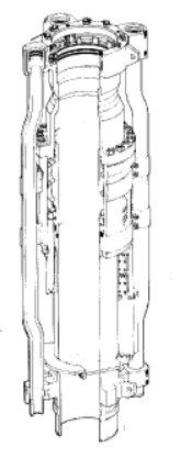
Although outwardly a simple piece of equipment, many complex design criteria must be considered when considering the marine riser. All components of the riser must have adequate strength to withstand:
- Dynamic loads while supporting and running the BOP package
- Lateral forces from vessel offset due to currents and wave forces
- Cyclic forces from vessel motion
- Axial loads from riser weight, drilling fluid density, and suspended pipe within the marine riser
- Axial tension from the tensioning system at the surface. Figure 1 illustrates that.
Riser joints are constructed from seamless pipe, usually grade X-52. Mechanical couplings are welded to each end of the joint, and the couplings usually incorporate a flange that supports integral kill and choke lines (Choke Manifold) and booster lines when fitted. The standard length for riser joints is 15.2 m (50 ft), but a range of shorter joints is also available for space out to suit different water depths.
Some drillships and large semi-submersibles can run joints up to 22 meters long to reduce pipe tripping time. Each rig’s physical layout will restrict the length of riser joints that can be handled. There are numerous systems for handling risers, but most rigs pull and run risers through the rotary table and V-door.
Preliminary Hints
The internal pressure rating of the marine riser system should be at least equal to the working pressure of the diverter system, plus the maximum difference in hydrostatic pressure of drilling fluid and seawater at the sea bed. In deep water offshore drilling, we shall consider riser collapse resistance in the event of lost circulation or disconnection of the marine riser while full of drilling fluid.
Integral high-pressure choke and kill lines, which provide the high-pressure communication between the BOP stack and the choke manifold on board the vessel, are permanently installed on the riser joints. Therefore, they are simultaneously made up when the riser is made up.
Using synthetic foam modules, additional buoyancy can be added to the riser for deep water applications. These modules are cast to specific dimensions, strapped to the riser joints, and can be removed when not required. Different grades of foam are available for different depths; however, all suffer from degradation due to water ingress and damage, decreasing buoyancy over time.
We must consider effective maintenance and regular inspection to ensure the safety of the drilling operation. This will be through visual, magnetic particle, and ultrasonic wall thickness inspections. In addition, keeping proper inspection and maintenance records is crucial.
Drilling Riser Connections
Riser pipe connections must have the same strength and pressure integrity as the riser pipe section. They provide a means of quick, reliable makeup and break-out and maintain an effective seal while withstanding the continuous flexing due to rig and sea movement.
There are several manufacturers of marine riser connectors, and each type of connection comes with its running tools. We will discuss both two systems below; both use similar principles in makeup:
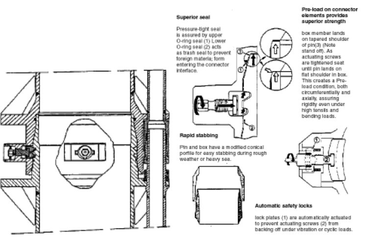
Vetco Series C Marine Riser Connector
The Vetco Series C marine riser connector is a rigid, pressure-tight joint that does not require rotation for makeup. Instead, the connector utilizes locking dogs located on bosses at the box member. Actuating screws within the bosses drive the locking dogs into a profile on the pin member. As you tighten the actuating screws, the locking dogs with tapered faces engage the grooves and start driving the end of the pin toward the tapered seat of the landing shoulder. This continues until the pin’s flat end lands on the landing shoulder’s flat part.
As you keep tightening, the pin’s end is compressed axially and circumferentially, with the load evenly distributed over the entire shoulder area. This creates a preloaded condition that assures the connector’s rigidity even under high bending and tensile loads. When the pin and box start to separate under load, the radially compressed end of the pin expands to maintain tight contact with the landing shoulder. This ensures that the connection remains rigid under all load conditions. One of the benefits of this connector is that it’s easy to change individual dog assemblies, and a few moving pieces can be lost in the hole.
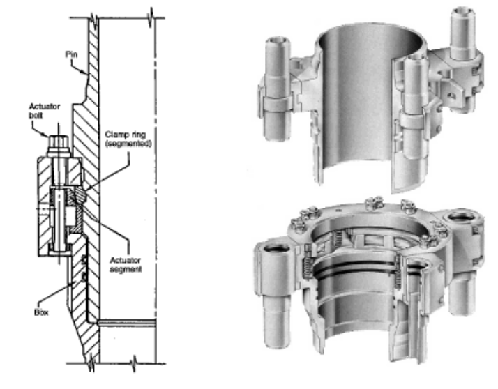
Cameron Rd Drilling Riser Connector
Cameron RD riser connectors are quickly made up of eight activating bolts, designed so that sequential tightening is not required. The activating bolts move segments that displace a two-piece locking ring to provide an even locking load distribution over a large contact area. By backing up the locking ring, the actuator segments prohibit junk build-up behind the ring. Viewports are provided in the box section to confirm the correct connector makeup visually. Spring-loaded locks on the actuator bolts prevent them from turning loose due to excessive vibration. This locking feature is overcome in the release mode when an impact wrench is placed over the actuator bolt.
A disadvantage is that you must lay out the whole joint if one dog fails. The dog assembly design is also complex and susceptible to lost pieces in the hole.
Ball Joints And Flex Joints
The marine riser system includes one or two flexible connections to minimize the stresses induced by rig and sea motion. These joints allow for angular movement at the top of the BOP package at the sea bed and just below the diverter at the surface. They enable an angular freedom of the riser of up to 10 degrees and are available in two designs: ball and flex joints.
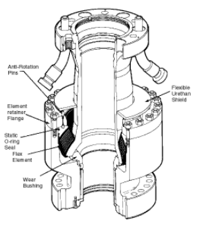
Hughes Cr-1 Ball Joint
The Hughes ball joint (Figure 4) provides angular flexibility up to 10 degrees with more strength than the riser. The large amount of steel in the ball combined with the replaceable wear sleeve provides good resistance to wear. An anti-rotation pin in the ball joint housing is helpful to prevent the ball from turning axially. A machined slot is cut into the ball to act with the pin. The moving mechanism is safeguarded against debris and drilling cuttings by a flexible protective boot attached to the neck of the ball joint..
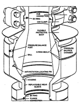
This piece of equipment is liable to wear and damage the ball, the socket, and the O-ring seals and requires much maintenance.
Ball-type joints require a pressure balancing system to offset unbalanced forces such as tensile load, drilling fluid density, and seawater pressure. This pressure balancing also lubricates the load-bearing areas of the ball and housing. It is fed to the ball joint via the hydraulic control umbilical from the surface. In addition, we can adjust it with a surface regulator on the main BOP control panel. However, as the upper ball joint only supports the weight of the slip joint inner barrel, the ball merely requires a cushion of grease rather than hydraulic pressure balancing.
Cameron Single Flex Joint
This type of joint flexibility is achieved by using a series of laminated metal plates bonded to a resilient material. The Cameron flex joint allows a maximum deflection of 10 degrees.
These flexible joints do not require pressure balance or lubrication. In addition, unbalanced forces have no effect on flexible joints not like ball joints. Therefore, many consider them more reliable than ball joints.
Telescopic Joint
Utilizing the telescopic joint, or slip joint on top of the marine riser below the flexible joint will provide the following functions:
- It compensates for the vertical motion of the vessel caused by waves, tide, draft, and vessel offset.
- It provides a means of connecting the diverter and flow line to the riser system.
- It provides termination for the flexible choke and kill lines.
- It provides the attachments for the riser tensioning system in the inner barrel.
The slip joint consists of an outer barrel attached to the top of the marine riser and an inner barrel attached to the upper flexible joint. The inner barrel slides in and out of an outer barrel, allowing a stoke varying from 13.5 to 16.5 m (45 – 55 ft) while maintaining an annular seal. The outer barrel houses pressure-energized resilient packing elements, which affect a seal around the inner barrel when energized. These packing elements must have the same internal wellbore pressure rating as the diverter system.
Working Principle
The outer barrel includes the support ring or fixed pad eyes for attaching the riser tensioner lines. A support ring can rotate on Teflon pads, preventing torque from transmitting to the lower riser ball joint. In cases where the vessel has a dynamic positioning system, we may use a full swivel ring with bearings to enable it to face prevailing weather conditions. The outer barrel includes termination points for integral riser kill and choke lines; flexible transition hoses continue these lines to the vessel’s hull.
You can mechanically lock the inner barrel in the closed position to handle the BOP, transport it, and make it easier to handle on the rig. Landing the BOP and riser string on the wellhead with a fully extended inner barrel is not advisable. This is because the load shoulder or shoe of the inner barrel may not be in good condition, and we can’t always know its condition.
Annular Preventer (LMRP)
The Lower Marine Riser Package (LMRP) includes the lower flexible joint, an annular preventer, and a hydraulic connector. This arrangement allows closing the well using the BOP package and disconnecting & retrieving the LMRP if possible.
The annular preventer included in the LMRP can be part of the BOP package (as the second annular preventer) while connected to the BOPs but will be part of the riser when disconnected.
The design and operation of this annular preventer is the same as the one in the BOP package.
Marine Hydraulic Connector In Drilling Riser
The primary application of hydraulic connectors is to give us complete control to connect or disconnect remotely:
- The BOP stack to/from the wellhead
- The LMRP to/from the BOP stack
The rated working pressure of a connector should be equal to that of the preventer above the connector, and the mechanical strength of the connector should be sufficient to withstand tensile, compressive, and bending loads encountered during sub-sea use.
Different manufacturers make hydraulic pin connectors, which are not interchangeable since they latch on different profiles. The offshore drilling contractor will supply connectors and test stump(s) as part of the BOP/ riser package, but these are only sometimes compatible with the wellhead.
The LMRP connector should be able to operate, especially unlatch, with a certain amount of riser angle. This requirement becomes more critical as water depth decreases since riser movement in response to sea conditions becomes more exaggerated. A rig moving off location with station-keeping difficulties may have to perform an emergency disconnect procedure with the riser angle increasing rapidly. The need for the LMRP connector to have a degree of angular tolerance, particularly for the disconnect function, has made this a critical feature of connector design.
Many oil and gas companies use AX or VX ring gaskets between the connectors. Its design allows it to be held in the connector while being run. In addition, the design enables us to release and change the gaskets with the assistance of ROV or diver when in the water. This is essential to avoid pulling the BOP stack to change a damaged ring gasket.
We shall discuss two hydraulic connectors below: the collet type Cameron model HC and mandrel type Vetco H-4.
Cameron Model HC Collet Connector
The Cameron collet connector engages the lower hub utilizing clamp segments, which form a funnel to guide the connector into position over the mating hub. An annular/actuator ring with a large piston area applies a high locking force to the collet fingers. This high clamping force is necessary because the connectors’ lack of swallow and resistance to bending forces. Employing a larger area on the unlock side of the piston generates additional unlocking force compared to the lock side.
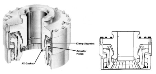
The HC connector will fit over the wellhead hub, and its swallow can be as small as 346 mm (13 5/8″). The actual size depends on the connector’s through bore and pressure rating, which can be as high as 15,000 psi. This makes it perfect for LMRP use where there is a need for release at high angles.
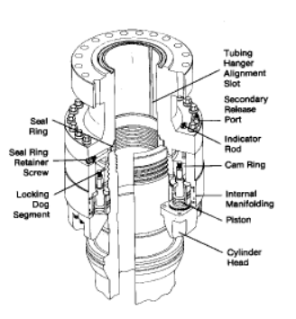
Vetco H-4 Mandrel Connector
The Vetco H-4 connector is a type of mandrel connector. The connector applies hydraulic pressure to the internal pistons, pulling a cam ring down behind the locking dogs. This forces the locking dogs to move inwards, allowing them to mate with the grooves on the BOP or wellhead mandrel. The hydraulic system used by the connector is designed to generate a more significant force during the releasing process rather than the locking process. This ensures generating enough force to overcome any frictional or other forces interfering with the release. To achieve this, split the operating system in half. Only half of the operating cylinders function during the locking process, but we can use all of them to release the connector.
Other Vetco Models
Vetco produces three variations on their H-4 connector, all models operating on the same principle, covering a range of sizes and pressure ratings for different applications:
- Standard H-4 connector
- High-angle release H-4 connector
- Heavy-duty H-4 connector
The standard H-4 Connector is the basic model suitable for most applications. The large swallow of 698 mm (27 1/2″) ensures good resistance to bending even before the hydraulical locking of the connector.
The high-angle release H-4 connector will maintain releasing capability under angles of up to 10 degrees of riser deflection. To achieve this, the connector has been designed to engage with a minimum swallow of the pin.
The H-4 connector is a heavy-duty component that can endure severe tensile and bending stress by increasing the connection preload. To achieve the extra unlock force, the connector utilizes the larger piston area on the unlock side of the pistons due to the stem on the lock side. Mechanical unlock is enabled through the 45-degree taper on the locking dogs. When shifting the cam ring to the unlock position, an upward pull on the connector body will push the locking dogs out of contact with the mandrel.
Dump Valve And Anti-Collapse Valve In Offshore Drilling Riser
Three other components may be incorporated into the riser depending on the expected conditions. These are a dump valve, an anti-collapse valve, and a booster line connection.
We usually install a riser dump valve just above the pin connector. This will help to dump cuttings-laden drilling fluid returns from the riser when experiencing losses due to the increased hydrostatic head in the offshore riser annulus. When encountering weak formations, drilling with returns to the sea bed facilitates drilling.
An Anti-Collapse Valve (ACV) for deep water marine risers affords quick opening of the riser bore to combat collapse of the pipe when there is a sudden reduction in the fluid column pressure head, e.g., due to severe losses or large amounts of expanding gas entering the riser in case of a shallow gas kick. It can be located at any depth in the riser string to optimize performance.
A pressure sensory sleeve activates the Cameron ACV or riser fill-up valve when the pressure inside the riser is 250 to 350 psi below ambient water pressure. When activated, the valve fully opens to fill the riser rapidly. After pressure equalization, the pressure sensor will return to its original position, and the internal sleeve will close. This self-contained valve doesn’t need any external control lines. Nonetheless, we can also operate it manually through control lines from the surface.
Drilling Riser Operating Criteria
In the analysis of drilling risers, we should keep in mind three primary parameters:
- Structural stability of the riser system.
- The various angles the riser makes with the slip joint and lower ball joint.
- Fatigue stress is due to the cyclic variation of stresses caused by rig and riser motion.
The initial exercise of a riser analysis is to define a set of operating criteria for the individual components of the riser system. This comprises a list of prevailing conditions during which operations can proceed normally, need to be restricted or suspended. We shall choose conditions used for riser analysis to be within the rig’s station-keeping capability. Ideally, the mooring and riser systems should have equal capability, but the mooring system is more robust.
The following table illustrates seven essential factors that analysis usually include:
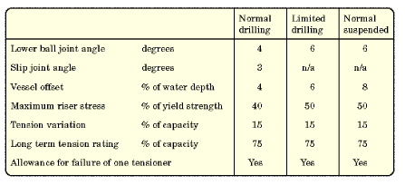
The table above classifies to what extent operations can proceed under the prevailing environmental conditions. The Operations Manual of the rig describes the definitions of the operating parameters; check the below example:
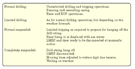
Worst Case
It is essential to realize that these figures relate to the ‘worst case’ and we would not expect to see it daily. The quoted figures are ‘typical’ and will vary between Drilling Contractors and the equipment used.
Continuing with the drilling operation is not advisable or even possible if these ‘worst case’ figures exceed instantaneous readings. It is unlikely that any vessel could operate continually with an offset of 4 to 6%, regardless of marine riser tension, without resulting in severe damage caused by drill pipe wear to the lower ball joint, lower offshore riser joints, BOPs, and hydraulic connectors.
Additionally, the large ball joint angle and vessel displacement will not allow the running of the casing hanger, wear bushings, seal assemblies, well packers, and test tools. This is because it will require a low drift angle through the ball joint. High trip drag, difficulty setting drill pipe slips and rotary drive bushings (especially in shallow water), severe wear in wear bushings, and the production of metal shavings (results of wear in sub-sea equipment) would also be evident with such large offsets.
Offshore Drilling Riser Space Out
To space out the marine riser system accurately, choose the proper lengths and number of riser joints, including full-length and pup joints. Consider water depth, tidal variations, air gap, vessel draft, wellhead height, BOP, and LMRP dimensions. When correctly deployed, the slip joint inner barrel and riser tensioner rods should extend half their stroke length at zero heaves and mean tide.
With the complication of tides and varying semi-submersible drafts, it becomes quite complicated to calculate correctly the correct space-out. Most semi-submersibles vary their draft according to the environment by as much as 6.1m (20 ft). With tides as high as 9 m (30 ft) in places like Alaska’s Cook Inlet and Baffin Island, we shall consider proper calculations to allow full slip joint utilization. Slip joint stroke lengths vary from 12.2 m (40 ft) to 22.9 m (75 ft), with the most common ones being 13.7 m (45 ft) and 16.8 m (55 ft).
Large Tides
The figure used for the water depth should be the water depth at the location at mean tide. If large tides are present, calculate for the low and high tides. With the latter completed maximum rig heave should then be estimated in conjunction with low and high tide to check if the slip joint will ‘bottom out,’ i.e., the down heave puts the riser in compression, or the up heave puts the entire riser in an ‘over tension’ situation. It is advisable that if tide and heave stroke the slip joint to within 1 to 1.5 m (4 to 5 ft) of ‘bottoming out,’ we should disconnect the riser.
Extreme Tides
In extreme tides, it is possible to deploy a riser tensioner cable handling unit, which alters the amount of active line in the tensioners to keep them in mid-stroke. This would be needed, for example, if 15.2 m (50 ft) tensioners were used with a 22.8 m (75 ft) slip joint.
After finishing the optimum riser length calculations, compile a running tally for the riser using a combination of the pup joints available to match the required length as closely as possible.
Drilling Riser Running Procedures
Generally, we utilize a handling sub with a riser connector at the bottom and a drill pipe tool joint at the top to pick up and run the offshore riser joints. The handling sub comprises a riser joint, which is subsequently connected to the rotary table. After the connection, lower the riser to place the next riser connector in the table.
Riser joints are connected in different ways depending on the type of connector used. Because of the riser configuration, particularly when fitted with integral choke and kill lines, it is necessary to use a riser handling spider to run the riser. The riser handling spider (Figure 7.4.12) replaces the slips and sits over the rotary table.
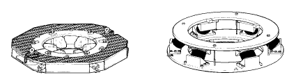
The riser is run through the spider, and each joint is landed in the spider to facilitate the connection of the next joint. The spider mechanism usually comprises a set of hinged dogs. These dogs are pivoted on the spider frame. In addition, they are folded down to enable the riser connector flange to land on them. Spiders that can gimbal, i.e., evenly distribute the loads on the riser and the spider while also reducing slack, are far safer than conventional spiders, where on rough seas, the load may be only supported on one or two dogs at times.
General Consideration While Running
Riser running procedures vary depending on the type of rig and equipment used. Below are some general considerations:
- A riser double is usually made up before picking up the BOP package with the riser. On a semi-submersible, this allows the initial lowering of the BOP to stop with the whole BOP below the splash zone. The seawater dampens any swinging motion of the assembly before making the first riser connection. On a drillship, this allows running the BOP to a position well below the vessel, reducing any chance of collision between the BOP and the bottom rim of the moonpool.
- Generally, we move the rig some 20 meters off location to avoid anything dropping on the wellhead while running the riser.
- Run and land the BOP package with the slip joint locked. Use the motion compensator to control vessel motion and landing weight.
Instrumentation
Several instrumentation designs are available to measure the riser angle relative to the vertical to determine when a riser is in danger of overstressing. The required degree of instrumentation will vary according to anticipated operating and environmental conditions.
Riser Vertical Angle Indicator
The angle of approach of the offshore riser to the BOP stack must be as small as possible to minimize wear by the drill pipe. Experience has shown that maintaining an angle of less than one degree minimizes problems. As rig personnel adjusts riser tension and vessel position, we can achieve to maintain alignment.
To do this, we must know the angle and direction of displacement of both the BOP and the riser. Note that we may land a BOP on a non-vertical wellhead. Generally, there are three methods of measuring and monitoring BOP stack/riser alignment:
- The bull’s eye is the most straightforward and reliable instrument, comprising a steel ball in a concave dish. The dish is marked with concentric rings, usually to give one-degree increments. Therefore, when the ball is in the center of the rings, it indicates zero-degree deflection. One bull’s eye is mounted on the BOP frame, one on the wellhead, and another on a frame on the riser above the lower ball joint. They may be read with a sub-sea TV or by deploying an ROV.
- Another system incorporates rheostats measuring the angle of pendulums mounted in waterproof containers. These are mounted with one unit below the lower ball joint (BOP angle) and another on a frame on the riser. This system requires an electrical umbilical to take a read-out at the rig’s surface.
- A modification to the previous method employs acoustic beacons, one on the BOP and one on the riser, to transmit information on direction and angle through the water to a surface unit for interpretation. As there is no requirement for an umbilical, we can mount a beacon on the BOP itself and remain operable even with the LMRP unlatched.
Hole Position Indicator.
By mounting a transponder on or close to the BOP stack, we can monitor the hole position relative to the rig. After receiving the signal from the transponder on the vessel, the instrument will calculate and show the offset of the vessel from the hole on its display.
Marine Drilling Riser Stress And Tension Indicators
We can monitor stress in the riser by strain gauge clusters placed at a selected elevation, usually nearer the lower end of the riser. Maintaining and recording riser tension near the bottom allows the operator to identify buoyancy loss in a buoyant riser immediately and allows monitoring of the highly stressed riser in deep water applications.