Drawworks Brake System can be divided into:
- Main Brake (Stationary Brake)
- Auxiliary Brake
MAIN BRAKES (STATIONARY BRAKES)
The main brake of a drilling rig is the mechanical band brake or the hydraulic/ mechanical disk brake system. As the name implies, the primary method of stopping the draw-works drum is by the use of the main brake. It is, therefore, essential that the driller is familiar with its operation, adjustment and maintenance.
Drawworks Band Brake System
The brake assembly consists basically of two flexible steel-lined bands that fit around the drum flanges. Each drum band is anchored on one side while the other is free to move. The brake lever is attached to the free side utilizing a lever shaft. When applying the brake, the bands clamp around the drum flanges, and the friction will halt the drum. In addition, this friction generates considerable heat, so most drum flanges are provided with a water-cooling system.
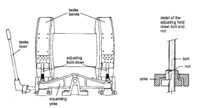
The brake bands are in line with brake blocks, improving the friction and allowing redressing of the brake bands. These are made of bonded asbestos fiber interwoven with copper wire and are shaped to fit the contours of the brake flanges. Brakes without asbestos fiber are under development. Countersunk brass bolts connect the brake blocks to the brake bands to avoid damaging the wear-resistant rims on the brake flanges.
Operation
When applying the brake, the segment nearest to the live end (i.e., the brake handle) comes into contact with the brake flange first with pressure dependent on the force applied to the handle. This starts to take up the load. Friction then brings the second segment into contact with increased tension and therefore increased pressure and frictional force. This braking action goes around the flange with ever-increasing values of tension and friction until it reaches a maximum at the dead end. A relatively light pressure on the handle can thus provide a very high braking torque. The brakes are self-energizing when lowering the load.
Capacity
The braking capacity of band brakes depends on the following:
- Firstly, the diameter of the drum flange.
- Secondly, the width of the drum flange and band.
- Thirdly, the angle of the band wrap around the drum flange (this should be at least 270°).
Equaliser
Typically each brake has to take half the load. For this purpose, the heavy adjustable hold-down bolts connect to an equalizing yoke, ensuring that each brake band will bear an equal amount of tension. The hinge of this equalizing yoke is bolted to the frame of the draw-works. If one brake band fails, the equalizer switches the whole load to the other band.
We must check the brake bands’ adjustment and condition regularly. Usually, we check the wear of blocks and rims according to schedule during rig downtime. The API values for allowable wear on rims apply, and they can be found in API Spec. 7 section 18.
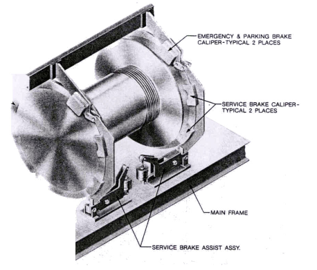
Drawworks Disc Brakes System
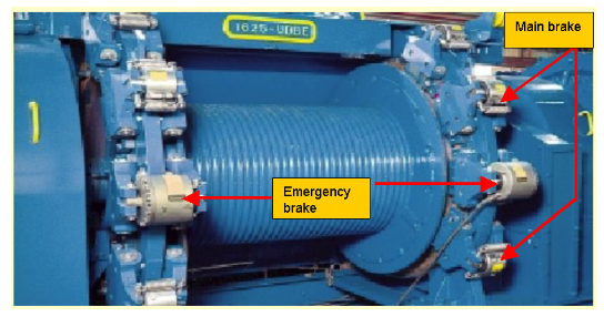
The disk brake system consists of three major components:
The Disks.
The system uses two hard-faced discs with an internal water jacket on either side of the main drum. The brake system disc thickness will vary from two to three inches depending on the drawworks size. Disc diameter usually is four to five inches larger than with brake bands.
The Caliper Assembly
Depending on the size of the drawworks, there are four or six brake system caliper assemblies (two or three on each disc). Each assembly consists of two brake pad assemblies (one on either side of the disc) and an operating cylinder mounted in the middle on top of the disc. The operating cylinder will move the brake pads at the end of the caliper arm onto the disc if hydraulic pressure is applied to the cylinder.
In addition to the hydraulically actuated calipers, each disc brake system includes two spring-set, hydraulically released calipers. During regular operation, hydraulic pressure keeps the springs compressed. However, in the event of complete loss of hydraulic pressure, electrical failure, or by operation of a manual valve, the springs extend and set the brake. These emergency calipers also serve as parking brakes when the rig is idle for short periods.
The Hydraulic System.
In a typical installation, the draw-works has its hydraulic unit with two pumps, a fluid reservoir, and accumulator bottles. The pumps usually work independently (one electrically and one air operated), and are set to maintain 2,000 psi (13,800 kPa) with a relief valve set at 2,250 psi (15,500 kPa). The two primary accumulators, isolated from each other by check valves, supply pressure to the two main valves at the driller’s brake handle. This drawworks brake is a dual system; the pressures to the two sides are entirely independent. Either side of the system can hold the maximum rated hook load.
Since it is a hydraulically operated system, the brake can be controlled from positions remote from the traditional driller’s position without complicated mechanical systems.
Operation
The operation of a disk brake is identical to that of a band brake; manipulate the lever to operate the brake. The more hydraulic pressure we apply, the faster we apply the brake. And further, the stronger the braking force. The difference with a brake band is that applying the braking action is evenly over the disc and is, therefore, more direct.
The advantages of a disk brake are:
- Significant noise reduction.
- Less downtime on change out of brake pads (non-asbestos type).
- Greater holding power because of less fade than a band brake.
- No brake handle “kick-back” caused by dragging brake bands.
- Ease of remote control and use of advanced controls.
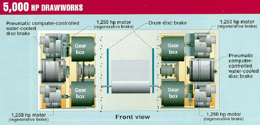
Regenerative Brake System (New generation of drawworks)
The newest generation of drawworks (4000-5000 HP), mounted on ultradeep offshore rigs, have a
the direct drive transmission system, permanently connecting the drawworks to the motors.
When the traveling block descends in the derrick, the motors turn in the opposite direction,
producing an opposite current and hence a braking action.
NOTE: This drawworks brake system, is not able to hold when the motors are resting, hence the need for
emergency and parking the disk brake system.
AUXILIARY BRAKES (DYNAMIC BRAKES)
Auxiliary brakes control the descent rate of the traveling block carrying a heavy load.
They serve to:
- Ensure that the load comes down slowly and smoothly.
- Reduce the wear of the mechanical brakes.
- Take shock loads and weight off the friction brake.
- Help to stop the traveling block before setting the pipe slips.
We should always engage auxiliary brakes to prevent accidentally dropping the drill string and traveling block. Even so, we should not lower the block too rapidly in case the auxiliary brake fails, and the load must be stopped only by the main brakes.
Hydromatic Brake
The hydromantic brake consists of a stator (C) with fixed blades (F) in which a rotor (A) with blades (E) can turn – refer to Figure 6.
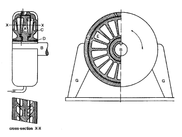
This brake’s operation is based on the fluid internal friction, usually water, which is sheared by the moving rotor. The mechanical energy from the shaft is converted into hydrodynamic energy. Because the stator blades do not transfer energy, all the hydrodynamic energy will convert into heat.
The amount of mechanical energy that can be absorbed depends on the following:
- The velocity of the rotor.
- The quantity of water in the unit.
Therefore: the higher the water level in the stator and the higher the speed of the rotor, the greater the friction and the stronger the braking action.
To adjust the power of the hydromatic brake, the driller has to adjust the water level in the brake by opening a valve in the cooling system.
There are various cooling systems (see Figure 8):
- Overflow or open system, if sufficient fresh water is available.
- Cooling tower or closed system, where the hot water flows over cooling trays and collects in a tank.
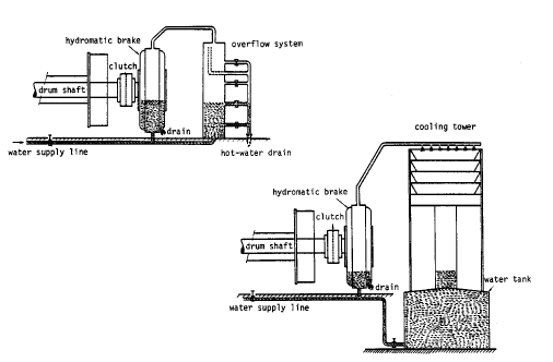
We are using an overrunning clutch, which engages in one direction but does not engage in the other, between the drum shaft and the hydromatic brake. As soon as we lower the traveling block, the clutch engages, “locks up,” and turns the brake rotor. The clutch is automatically disengaged while lifting the block.
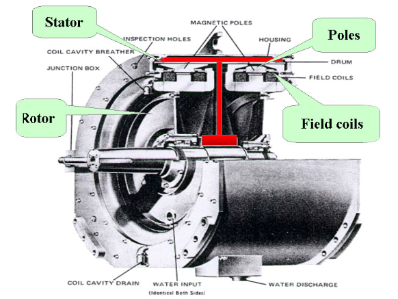
Electro-dynamic or Eddy current brake
Unlike “water brakes”, the eddy current brake develops exceptionally high braking torque at very low and high rotational speeds. When used within the rated capacity, the brake will slow the string enough to set the slips without using the drawworks friction brake system. This will eliminate the problems associated with overrunning clutches.
Due to its design, the braking force is produced without using any frictional braking device, slip ring, or other wearing element.
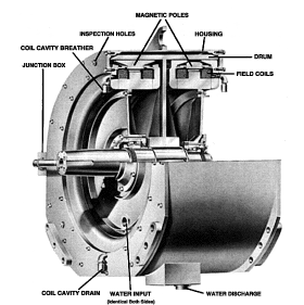
The brake consists of a steel drum rotated through a magnetic field produced by concentric electromagnets mounted inside the drum. By varying the current supply of these stationary electromagnets, the resistance exerted by eddy currents generated in the rotating drum can be controlled, thereby controlling the braking force. Because a large brake requires only about 20 kW, power is quickly supplied by standard AC plants.
Principles of operation
The electromagnetic field is excited by DC power from the driller’s control. The strength of the field varies with the current flowing through the coil. Magnetic lines of force (emanating from the poles when the field is excited) cross the air gap and pass into the drum. Rotating the drum (by the draw-works attached) through this stationary field will induce EMFs (electromagnetic forces). Therefore, it will produce a current flow in the drum.
These eddy currents vary directly with the lines of force cut by the rotating drum and inversely with the resistance of the drum so that the polarity of the magnetic fields in the drum is opposite to that of the stationary poles. The resulting mutual attraction creates the braking force and torque developed in the brake. Therefore, mechanical energy will convert to electrical energy, which will convert to heat energy without frictional rubbing elements that wear. In addition, we will need to replace it.
The housing is water-cooled to remove the heat.
Advantages
- High braking torque at low rotational speeds.
- Slips set without friction brake.
- No overrunning clutch.
- No belts, slip rings, bands, or other wearing devices.
- Continual dead weight and heavy shock loads were taken off the friction brake.
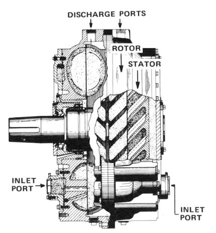
Magnetic particle brake (MPW brake)
Figure 10 is a cross-section of a magnetic particle drawworks brake system. This brake consists of a housing containing coils, a rotor, and a certain quantity of iron powder. Magnetic barriers and magnetic seals prevent the magnetic field, created when the coils are energized, from scattering.
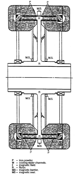
When the coils are energized, a magnetic field is created around them, and the iron particles are also magnetized and begin to “lump” together and form one mass with each other, the housing, and the rotor.
Unlike the eddy current brake, contact between the rotor and housing is now via the compacted magnetic iron powder. The rotor in the MPW brake does not need to rotate to supply the required brake torque.
We can increase or reduce the braking force by regulating the power supplied to the coil. The brake torque can reach very high values in this type of brake. Water cooling removes the heat generated.
COMPARISON OF THE VARIOUS TYPES OF BRAKE
In conclusion, Figure 11 shows draw-works brakes’ speed/torque characteristics.
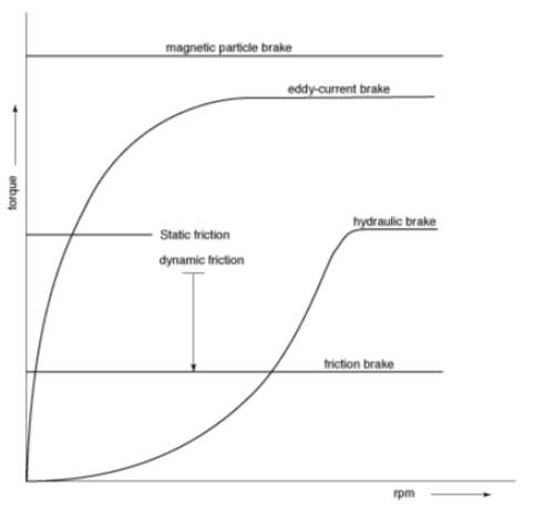
- Friction brakes may have very high static friction, but with a limitation of dynamic friction.
- Hydraulic or hydromatic brakes and eddy current brakes have no brake torque when the rotor is not turning. The torque increases as the speed increases. Eddy current brakes achieve maximum torque at lower rotating rates than hydromatic brakes.
- Magnetic particle brakes can supply a very high torque independent of the rotating rate and, like friction brakes, can hold the load.