The oil derrick and substructure are essential in drilling rig operations. The derrick provides the height necessary for the hoisting system to raise and lower the pipe. The greater the height, the longer the section of pipe that you can handle and, thus, the faster a long string of pipe you can run into or remove from the drilled hole.
Derricks can handle sections (stands) that have a composition of two, three, or four joints of drill pipe. Drill pipes are 8-10 m long, so a derrick for three stands is taller than a 10-story building. The substructure provides the height required for the blowout preventer stack on the wellhead below the rig floor. The derrick and the substructure must have enough strength to support all loads, including the hook load, pipe set in the derrick, and wind loads.
In general, an oil derrick in the petroleum industry is a pyramidal steel framework with square or rectangular cross-sections assembled as a fixed structure.
Derrick, large load-bearing structure from which the hoisting system and therefore the drill string is suspended.
A semipermanent structure of square or rectangular cross-section having members that are latticed or trussed on all four sides. This unit must be assembled in the vertical or operation position, as it includes no erection mechanism. It may or may not be guyed
API Definition
Substructures
Derricks and portable masts other than the telescopic type are supported by a heavy steel sub structure. The oil derrick transmits all the vertical loads through four points at the lower ends of the legs. The substructure transmits loads to the ground through large area of the flanges of the basal I-beams.. The design aims to keep the required bearing capacity of the ground within reasonable limits requiring less expensive foundations.
Note: Consider cellar depth when choosing substructure height for blowout preventer stack below the derrick floor.
Telescopic masts are usually mounted on wheeled units, and jacks support the loads. In addition, The bearing capacity is provided by inserting plates or beams under the jacking units. Such masts are helpful in relatively light work. Thus, the vertical loads are not as great as those experienced with derricks and the other type of mast.
Purpose & Application
Oil Rig derrick and mast in oil and gas have two functions.
- The primary function is to support the crown block (Drilling Rig Components).
- The lighter types of well-servicing rigs’ masts do not support tubular storage vertically in “stands” of three lengths. The masts are necessary to achieve proper “racking” of the tubular.
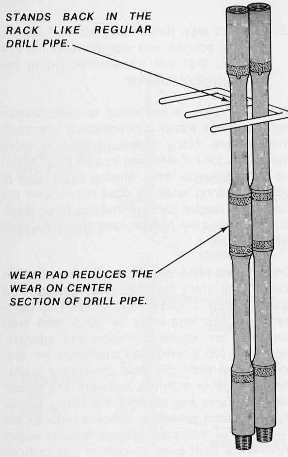
Unscrew only one of every three connections when removing the drill pipe for operations on the lower end. This technique will help save time while changing the drilling bit or carrying out other operations on the drill pipe lower end.
Most drilling units (Types of drilling rigs) use “stands” consisting of three (Range 3) drill pipe joints. However, some small workover units, use stands consisting of two joints, and some heavy rigs use stands of four joints.
Types of Derricks
There are mainly two types of derricks in drilling rigs:
- Firstly, stationary Type: Derrick used on offshore fixed structures
- On floating offshore drilling rigs, there is a more vital type of derrick called the dynamic type. This derrick consists of welded sections pinned together instead of being constructed using individual bolted beams. Unlike the standard API derrick, the dynamic type does not need frequent dismantling, making it more durable and reliable.
Components Of Standard Derrick In Drilling Rigs
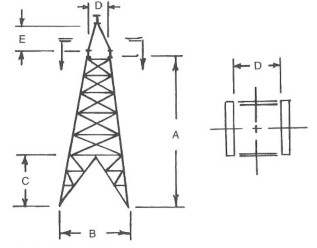
Figure 2 shows the so-called API standard oil derrick. It consists of four main legs of beams bolted together plus a series of horizontal girts and diagonal cross bracing, also bolted. The derrick is typically constructed from structural steel with a minimum yield of 224.4 N/mm2 (33,000 psi). In addition, the material has a hot-dipped galvanized surface finish. Furthermore, the derrick features a V-door on one side. This V-door has a higher opening at the bottom than the other sides. This is essential to allow for ample clearance to hoist forty-foot (12 m) lengths of pipe from the catwalk into the derrick.
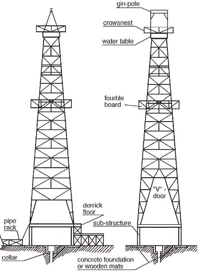
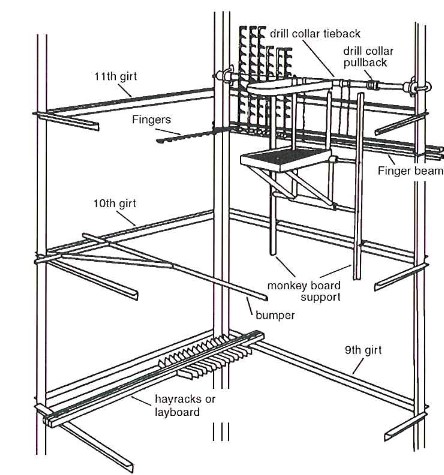
At a height of around 80 feet above the derrick floor lies the derrickman’s platform (the monkey board). From here, the derrickman operates equipment to handle the upper ends of the pipe stands and rack them neatly. This consists of “fingers” hinged to a bar fastened across two legs of the derrick. Figure 3 shows the details.
The crown block will be at the derrick top, with the axle supported in a structure called the water table. Above the crown is one single beam, that we call the gin-pole. The gin-pole will support a pulley block used solely to lift the crown into position.
Drilling Rig Derrick Construction In Oil & Gas
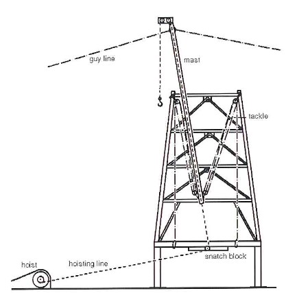
This construction allows transportation of the standard derrick on regular trucks and erection without heavy lifting equipment. In addition, there is a need for a specialist rig-building crew (Rig personnel), who construct it from the bottom up, with each successive layer lifted into place by a gin-pole supported by cables attached to the previous layers. Figure 4 illustrates this.
Every component of a derrick is crucial to carry its load share. Therefore, omitting or improperly placing any parts can contribute to the derrick failure. Every component of a derrick is crucial to its load-bearing capacity. Therefore, To prevent failure, it is essential to properly place & secure every component of a derrick. For this reason, tightening the nuts and bolts slightly beyond finger-tight during the initial construction is crucial.
Once erection of the entire structure, tightening all nuts and bolts will be to the required tension. This method ensures a more even distribution of stresses.
Unfortunately, the name “gin-pole” has been given to two different pieces of equipment related to the derrick – the connection is that they are both temporary lifting devices.
Derrick Sizes and General Dimensions In Drilling Rigs
| Derrick Size No. | Height (A) – ft | Height (A) – in | Nominal Base Square (B) – ft | Nominal Base Square (B) – in | Drawworks Window Opening (C) – ft | Drawworks Window Opening (C) – in | V Window Opening © – ft | V Window Opening © – in | Opening (D) – ft | Opening (D) – in | Gin-Pole Clearance E – ft | Gin-Pole Clearance E – in |
| – | ft | in | ft | in | ft | in | ft | in | ft | in | ft | in |
| 10 | 80 | 0 | 20 | 0 | 7 | 6 | 23 | 8 | 5 | 6 | 8 | 0 |
| 11 | 87 | 0 | 20 | 0 | 7 | 6 | 23 | 8 | 5 | 6 | 8 | 0 |
| 12 | 94 | 0 | 24 | 0 | 7 | 6 | 23 | 8 | 5 | 6 | 8 | 0 |
| 16 | 122 | 0 | 24 | 0 | 7 | 6 | 23 | 8 | 5 | 6 | 8 | 0 |
| 18 | 136 | 0 | 26 | 0 | 7 | 6 | 23 | 8 | 5 | 6 | 12 | 0 |
| 18A | 136 | 0 | 30 | 0 | 7 | 6 | 23 | 8 | 5 | 6 | 12 | 0 |
| 19 | 140 | 0 | 30 | 0 | 7 | 6 | 26 | 6 | 7 | 6 | 17 | 0 |
| 20 | 147 | 0 | 30 | 0 | 7 | 6 | 26 | 6 | 6 | 6 | 17 | 0 |
| 25 | 189 | 0 | 37 | 0 | 7 | 6 | 26 | 6 | 7 | 6 | 17 | 0 |
Tolerances For Standard Derricks in drilling rigs:
- A, The vertical distance from the top of the base plate to the bottom of the Crown Block support Beam, +/- 6 in
- B, The distance between heel to heel of adjacent legs,+/- 5 in
- C, The window opening measured in the clear and parallel to the center line of the derrick side from the top of the base plate, + 3 ft, 6 in
- D, The smallest clear dimension at the top of the derrick that would restrict the passage of the crown block, +/- 2 in
- E, The clearance between the horizontal header of the gin pole and the top of the crown support beam.,+/- 6 in
Pros & Cons Of Oil Derricks Above Over Masts
Conventional or standard derricks are used:
- Firstly, where many wells are in the exact location, there will be no need to dismantle the derrick to move it to the next cellar.
- Secondly, on small, tenderly supported platforms with insufficient space to assemble a mast horizontally.
- In situations where we cannot transport mast sections.
- When drilling deep wells on heavy-duty rigs, a standard drilling derrick provides a more stable layout with greater racking capacity than a portable mast.
Disadvantages of such derricks
- Specialist rig builders are crucial.
- Erection and dismantling are time-consuming. (But we can avoid time delays by “leap-frogging” two derricks.)
Manufacturer & IADC Specifications
Derricks are classified (or rated) by the American Petroleum Institute (API) according to their height and ability to withstand wind and compressive loads. API has published standards for the particular specifications. The higher the oil derrick is, the longer stands it can handle, reducing the tripping time. Derricks that are capable of handling stands of two, three, or four joints will be able to pull “doubles,” “thribbles,” or “fourbles” respectively.
Their manufacturing process will be within API 4F or related ISO recommendations. This specification covers the design, manufacture, and use of derricks, portable masts, crown block assemblies, and substructures.
- Spec 4E, Specification for Drilling and Well Servicing Structures, covers steel rig derricks, portable masts, and substructures suitable for drilling or well servicing. It includes stipulations of materials, loadings, conditions of loading, and allowable unit stresses intended to meet the requirements of present and future operating conditions, such as deeper drilling, offshore drilling from floating devices, and the effect of earthquakes, storms, and other adverse conditions. An appendix contains recommendations for the maintenance and use of drilling and well-servicing structures.
- Also, Spec 4F, Specification for Drilling and Well Servicing Structures covers the design, manufacture, and use of steel derricks, portable masts, crown block assemblies, and substructures suitable for drilling and servicing wells. It includes stipulations for marking, inspection, standard ratings, design loading, and equipment design specifications.
Drilling Rig Mast and Oil Derrick Nameplate Information
- Manufacturer’s name.
- Manufacturer’s address.
- Specification 4F.
- Serial number.
- Height in feet.
- Maximum rated static hook load in pounds, with guy lines if applicable, for the stated number of lines to a traveling block
- Maximum rated wind velocity in knots, with guy lines if applicable, with a rated capacity of pipe racked
- The API specification and edition of the API specification under which the structure was designed and manufactured
- Manufacturer’s guying diagram for structures as applicable
- Caution: Acceleration or impact, a setback, and wind loads will reduce the maximum rated static hook load capacity
- Including the manufacturer’s load distribution diagram in the mast instructions is important to ensure proper load distribution.
- Graph of maximum allowable static hook load versus wind velocity
- Mast setup distance for a mast with guy lines.
Periodic Inspection
The API applicable references are API RP 4G, API RP 54, and the Manufacturer’s recommendations. Some companies are more strict and require the API Category IV inspection (as per API RP 4G) every 5 years instead of 10. Mast/derricks and substructures on mobile offshore drilling oil rigs or fixed platforms are exempted from Category IV inspection requirements.
If you detect damage or concealed damage in any section or part of the structure, report it immediately and paint the damaged area with a highly contrasting color. Even slight damage in certain areas may be sufficient cause to condemn the structure until repairing it. Contact the manufacturer, give him the size, type, and serial number of your structure, detail the damage for him, and follow his advice concerning structure loading and repairs.
Fixtures and accessories are preferably attached to a structure by suitable clamps. Do not drill or burn holes in any members or perform any welding without obtaining approval of the manufacturer.
Oil Rig Derrick Capacity In Drilling
The ratings for all types of derricks and masts are specified by the manufacturers by the standards. These include a design given in API Specification 4F “Drilling and well-servicing structures”. These include a design factor of 50% for steel derricks when new. However, the ratings of used equipment should be reviewed regularly after inspection by the manufacturer or insurance company surveyor.
Ratings given include:
- Maximum hook load, i.e., the maximum string weight, including the weight of the travelling block.
- Maximum setback capacity, i.e., the maximum weight of drill pipe and drill collars that can be racked in the derrick or mast.
- Maximum wind velocity with the full setback.
- Pitch and roll tolerances (for offshore applications).
- General depth rating for a given size and weight of drill pipe.
It is, therefore, essential to be familiar with the capacity of the derrick or oil & gas drilling rig in use. The necessary information can be obtained from the following:
- The manufacturer’s nameplate gives “Mast and Derrick Name Plate Information”.
- Substructure Name Plate Information.
- Manufacturer’s operating instructions.
The following strength and capacity factors should be taken into account to prevent the derrick or mast from being overloaded:
- Maximum anticipated casing load design. (Although a rig may be rated to drill to a certain depth, it may not be designed strong enough to run casing/conductor heavier than drill pipe to that same depth.)
- Anticipated wind load or other exceptional conditions e.g., dynamic derrick foundations as on a drill ship.
- Substructure (base) setback capacity.
Field welding is not normally allowed on masts or derricks. Where this is unavoidable high grade welding rods have to be used under special procedures. During welding a representative of the manufacturers will have to be present. It will then be necessary to have the mast or derrick inspected by the certifying company.
Rig Derrick & Mast Drilling Loads
During operation, oil derricks and masts are subjected to vertical forces arising from the load carried by the traveling block and hook and horizontal forces arising from the pressure exerted by the wind.
On a floating unit, the derrick will oscillate as the vessel rolls and pitches, resulting in the hook load having a lateral (relative to the derrick) component. The movement of a floating vessel will also generate inertial loads in the derrick, but the period is so long that these will be insignificant relative to the other loads.
Vertical forces
In general, Figure 4 shows one possible arrangement of the drilling line, the fast line, and the dead line (the fast line and the deadline are the names given respectively to the sections of the drilling line between the crown and the draw-works and between the crown and the point where the line is made fast on the substructure. The latter is known as the deadline anchor). The arrangement shown would be described as having six lines strung because six segments of the line support the traveling block.
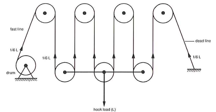
Figure 4: Ignoring friction, the tension in the line is = Hookload / N
- N = the number of lines strung.
- Hook load = load on hook + weight of traveling block
It is important to note that because the ends of the drilling line are attached at rig-floor level, two more lines are pulling down on the crown block than there are pulling up on the traveling block. It follows that:
Derrick load = Hook load + Pase line load + Dead line load
Static Derrick Load
The static derrick load (ignoring the weight of the oil derrick plus crown block) occurs when the block is not moving but is carrying the full hook load. Because there is no friction affects the fast line load, and the deadline load are both equal to the line tension and:
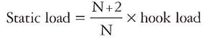
In general, derricks and masts in drilling rigs are designed to have a static load capacity for a specified number of lines and with an established position for the deadline anchor. Accordingly, changing the number of lines strung or moving the deadline anchor position will considerably alter the static load capacity.
Dynamic Derrick Load (crown load)
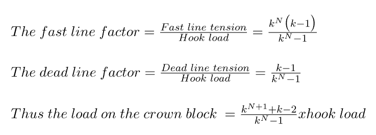
The dynamic rig derrick load is the load that occurs while running in or pulling out a drilling string or casing string. The oil derrick load is still the sum of the hook load, the fast line load, and the dead-line load, but in this case, friction plays a part – which is a combination of the bearing friction of the sheaves and the internal friction within the line as it is bent round the sheaves.
Friction
To balance frictional forces the tension in a line increases by a factor “k” as it passes over each sheave. This assumes that the frictional forces are directly proportional to the load on the sheave and that the line wraps around 180° of the sheave. The latter is true for the lines which pass around the sheaves in the traveling block and is approximately true for the fast line and the deadline.
In drilling line calculations, allowance is made for friction using factors derived from the above-mentioned factor “k” and the number of lines strung.
K Value
API RP 9B quotes a value of 1.04 for “k” for roller-bearing sheaves, which are the most common type. Substituting this figure in the above equation and comparing the result with the static derrick load indicates that the dynamic load on the derrick is insignificantly higher than the static load. The increase due to friction varies from 1 % with only two lines strung (i.e., a single sheave traveling block) to 0.5% with ten or twelve lines strung.
Nore, however, that the changes in fast line and deadline tensions are far from insignificant. With ten lines strung the dynamic, fast line tension will be some 23% higher than the static line tension, and the dynamic deadline tension will be 17% less. What is even more significant is that if the weight indicator sensor is on the deadline, which it usually is, the dynamic fast line tension with ten lines strung will be almost 50% higher than the figure shown by the weight indicator.
Shock Loads
As shock loads are difficult to calculate, rigs are designed to twice their rated strength (the design factor of 50% previously mentioned). Shock loads occur when a string is picked up from the drilling slips, and there is the acceleration of the string, and when the brake is applied, decelerate it. The tripping of a hydraulic jar or mechanical jar will induce shock loads (shock absorber), although most of the energy is transmitted to the stuck pipe.
The harsh acceleration or deceleration of a heavy string can result in large inertial forces developing capable of overloading the oil derrick or mast. It is also possible that the block line or the string could break in such circumstances. For this reason, the inertial forces should be reduced as far as possible when the rig is handling heavy loads by braking and picking up the string with care.
Wind load
The wind load on a derrick with a rack full of drill pipe results in considerable transverse forces.
Derricks and masts are constructed as per API Spec 4F to comply with a maximum wind load specified for that drilling rig. Most derricks and masts can withstand a wind load of 45 – 58 m/s (100 – 130 mph) with the racks full of pipe.