What a drilling fluid program should deliver
A drilling fluid program explains how the proposed fluid system will support the objectives of each well interval, what conditions may challenge it and what evidence is needed to accept and maintain the plan. It connects the fluid choice with the well design, testing, equipment, materials, logistics and contingencies. A product list or a column of target properties cannot do that work on its own.
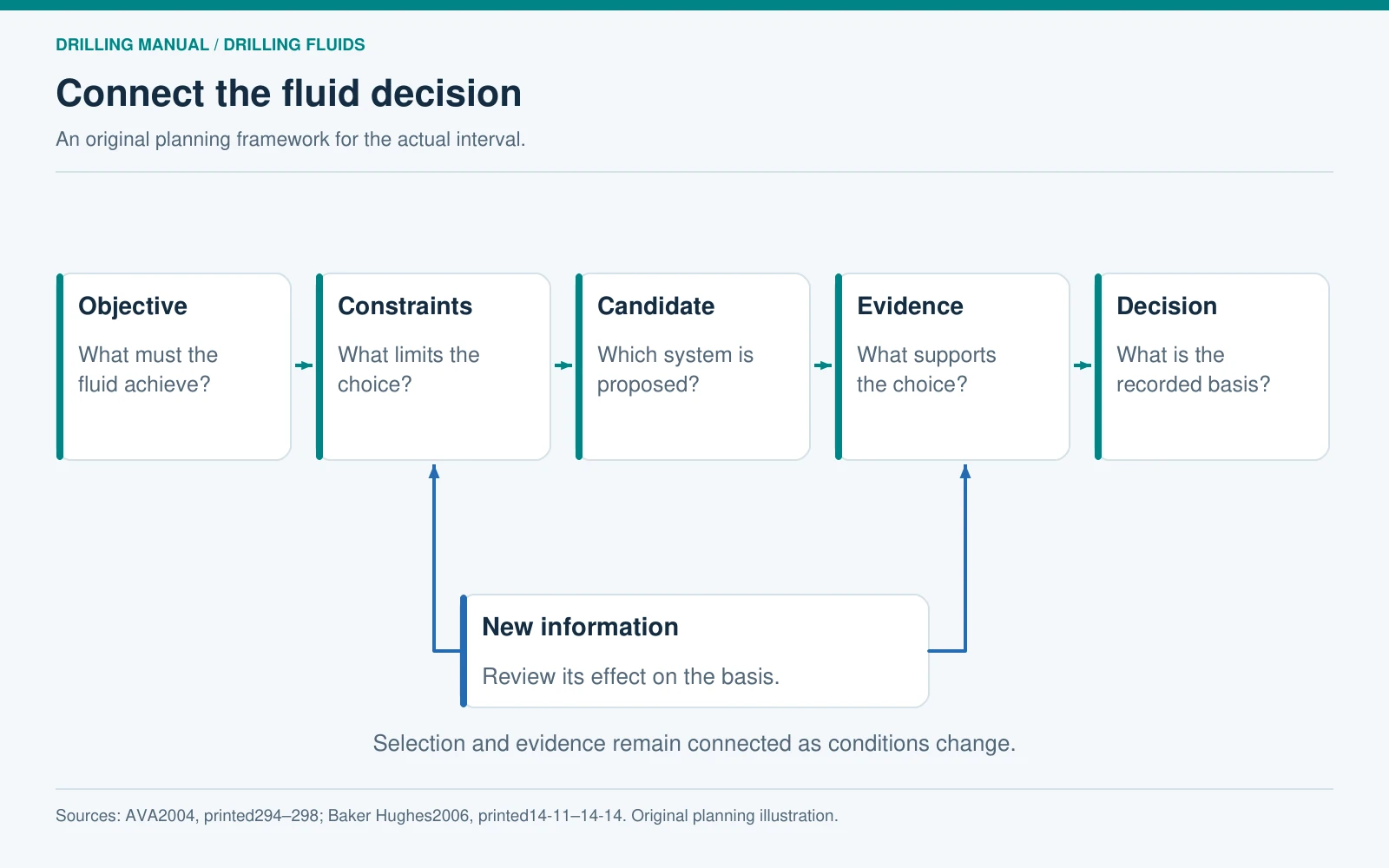
The AVA manual approaches selection by defining the interval objective, identifying the constraints and then assessing suitable systems. Its planning section includes geological and engineering information, laboratory results, offset experience, material and volume estimates, solids control and contingencies. Those connections provide the foundation for the original planning structure in this article. [1, pp. 294–298]
The broader drilling program coordinates the well as a whole. The fluid program develops the fluid-related decisions in detail. The daily mud report subsequently records what happened and what was measured. Keep the intended plan, its approved revisions and the actual operating record identifiable.


Start the drilling fluid program with interval objectives
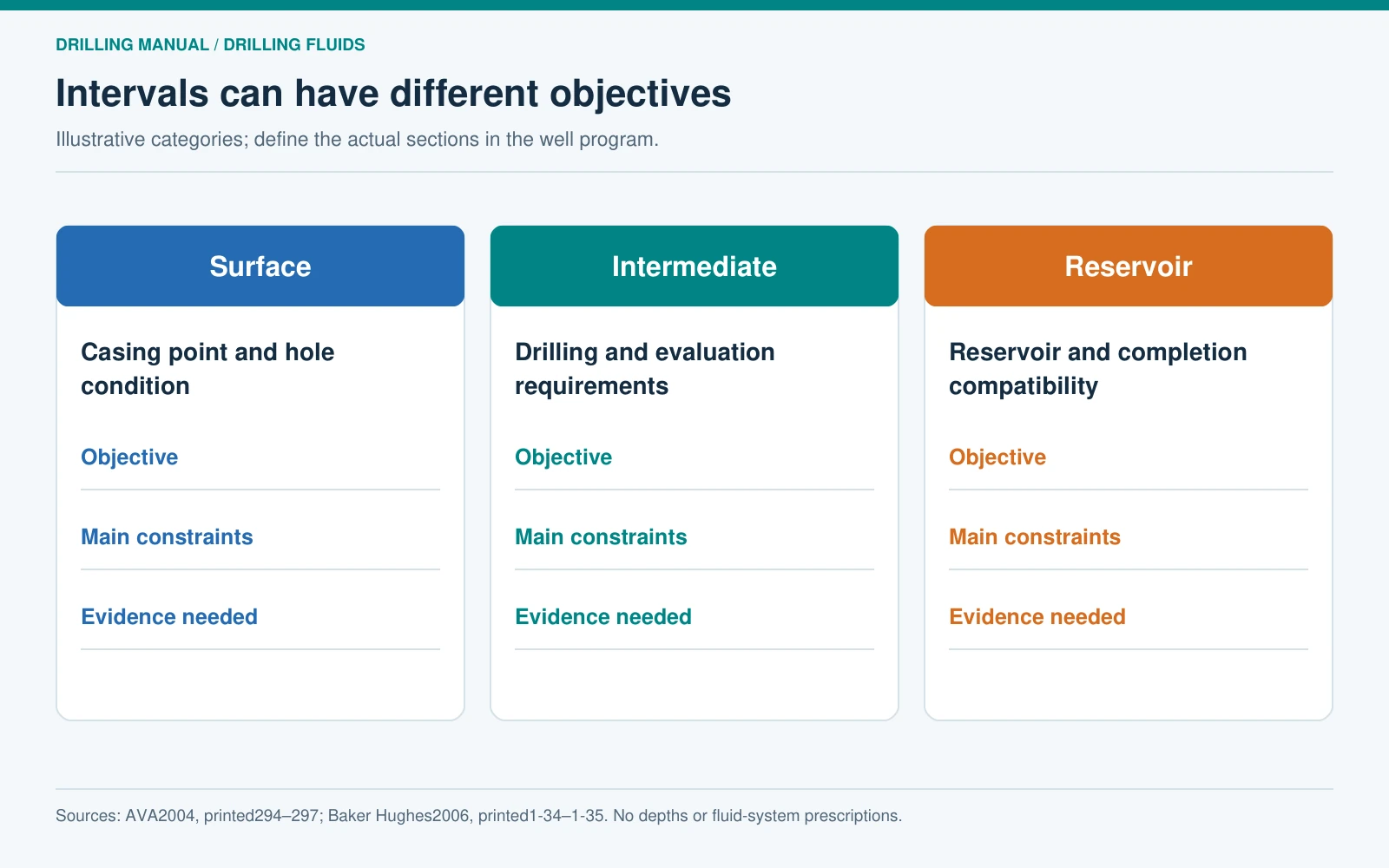
Separate the well into the intervals that matter to the design, using the agreed depth reference and boundaries. Define the result needed from each interval before naming a fluid system. AVA describes engineering and geological objectives and explains why the relevant constraints can differ between surface, intermediate and producing intervals. This is a planning approach, not a requirement to use a different fluid in every section. [1, pp. 294–295]
| Planning view | Example objective to define | Question for the fluid program |
|---|---|---|
| Surface interval | Reach the planned casing point with the required hole condition | Which expected formations and operating conditions could prevent that result? |
| Intermediate interval | Drill and evaluate the specified section while meeting its stability and hydraulic requirements | What evidence supports the proposed system over the intended interval? |
| Reservoir interval | Meet the evaluation or production objective while addressing reservoir compatibility | Which reservoir and completion requirements change fluid selection or testing? |
These are illustrative objectives, not a well design. Record the actual purpose in the program. An exploration interval may place particular importance on obtaining interpretable information, while a producing interval also needs a clear connection to the planned completion and reservoir protection.
Do not automatically inherit the preceding interval’s fluid choice. Equally, do not propose a change merely because a casing boundary exists. Assess continued use, conversion and replacement against the next interval’s demands and the practical consequences of each option. [1, pp. 294–297]
Separate design inputs from assumptions
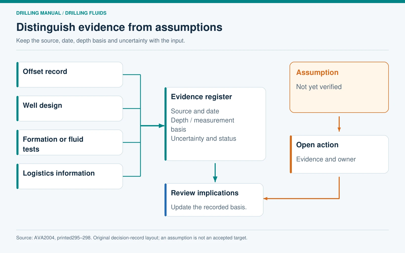
Build a drilling fluid program evidence register before treating the fluid proposal as settled. Relevant inputs include the well profile, pressure and temperature information, lithology, casing depths, offset records and expected formation behaviour. AVA also includes safety, environmental constraints, logistics, testing facilities, mixing, solids control and storage in the selection review. [1, pp. 295–298]
For each input, retain its source, date, depth basis and uncertainty. “Offset well performed well” is incomplete unless the comparison identifies the interval, fluid, operating circumstances and the problem being addressed. A property value copied from an offset is evidence to assess, not an automatic target for a new well.
Keep unsupported assumptions visible. For example, an original planning entry might read: “Interval B contains a potentially water-sensitive formation; the current evidence is an offset description; representative sample testing remains pending.” The corresponding action is to obtain the missing evidence and review the candidate system. The entry should not silently become a claim that one inhibition mechanism is already proven suitable.
For a reservoir section, Baker Hughes specifically identifies reservoir-fluid composition, lithology, clay content, hole geometry and the completion plan as information needed before recommending and testing a drill-in fluid. That is a distinct input set, not merely a tighter version of an ordinary mud-property table. [2, pp. 1-34–1-35]
Make each property requirement measurable
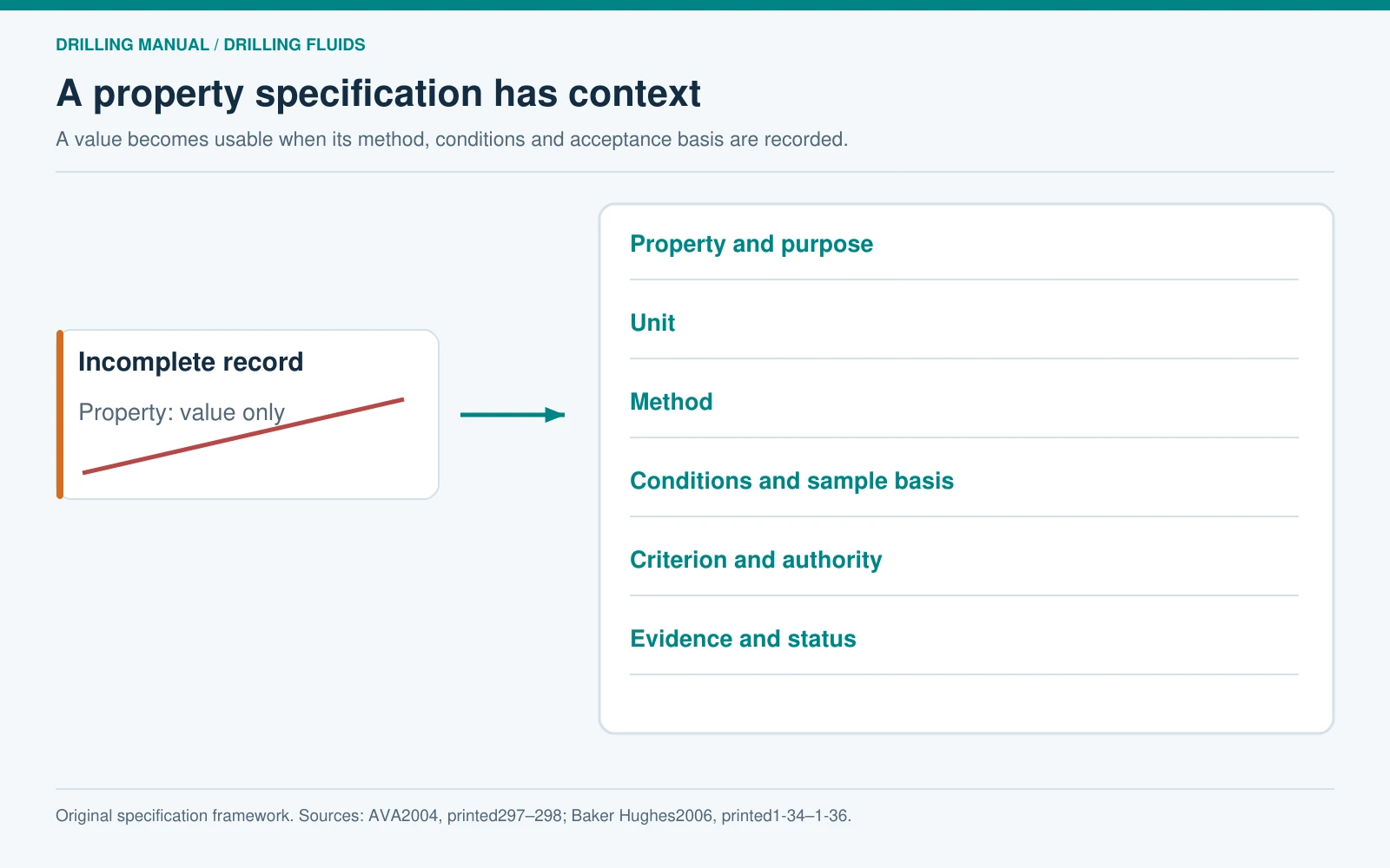
A drilling fluid program needs more than a property name and a number. State the purpose of the requirement, the unit, the test or calculation method, relevant conditions and the basis for acceptance. AVA identifies density, rheology, salinity or polymer content, alkalinity and filtration among important properties, while also requiring laboratory results within the program. [1, pp. 297–298]
| Field | What to enter | Why the reader needs it |
|---|---|---|
| Requirement and purpose | The property or performance outcome and the interval objective it supports | Connects the test to the engineering decision |
| Method and conditions | Method identifier, sample basis and applicable temperature, pressure or conditioning | Makes results interpretable against the specified requirement |
| Unit and acceptance basis | Unit, proposed range or criterion, supporting design reference and approving authority | Distinguishes a candidate value from an accepted requirement |
| Evidence and status | Report reference, unresolved limitations and review status | Prevents an incomplete test from appearing to close the decision |
This specification record is an original template structure. It deliberately supplies no universal mud density, rheology, filtration or salinity target. A blank engineering criterion should be marked “requires design input,” not filled with a convenient example.
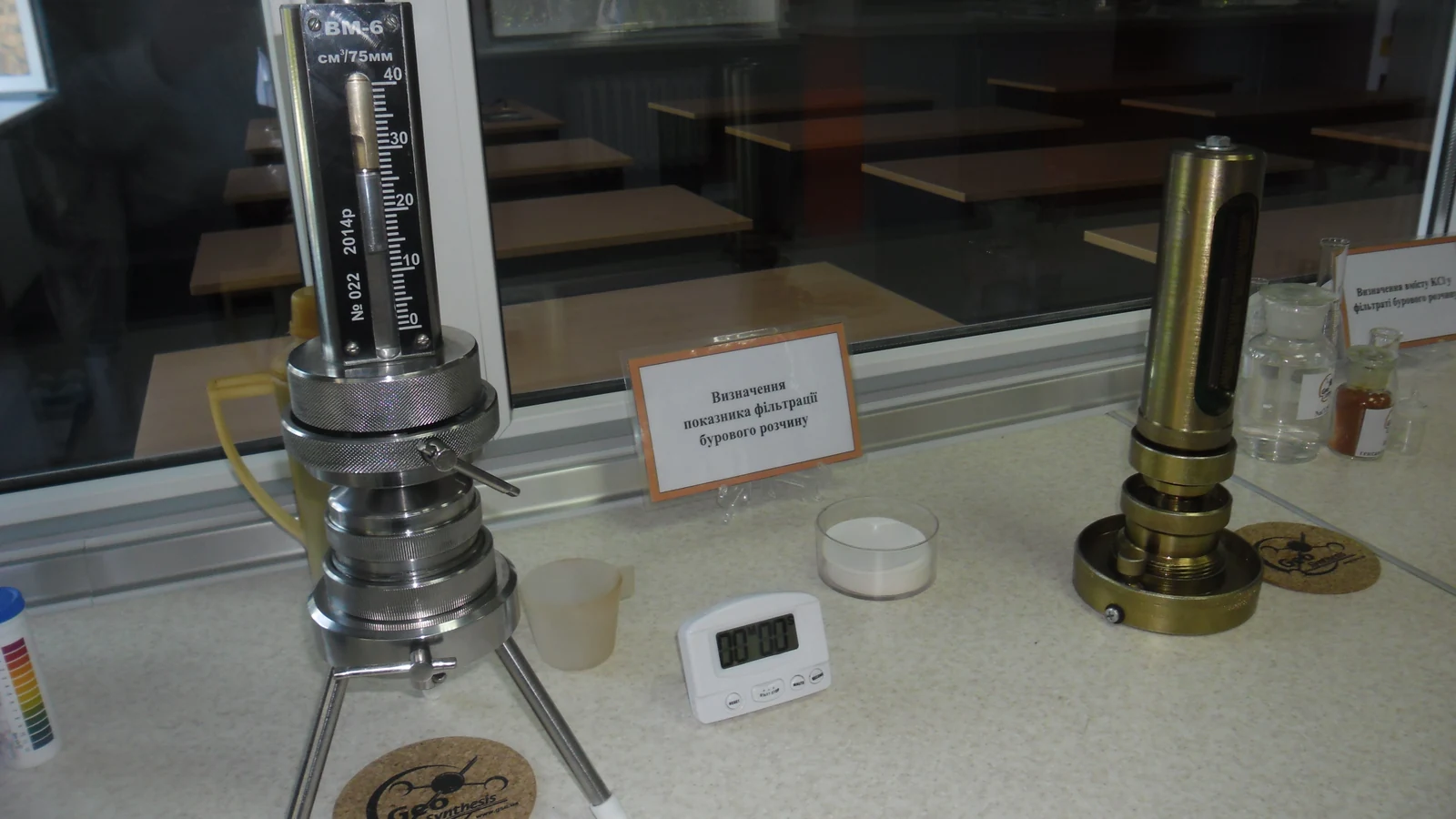
The guides to drilling-fluid properties and water-based mud testing provide related background. The program’s job is to identify which measurements apply and how their results support this particular well.


Use test evidence to compare the candidate systems
Keep the proposed fluid and its supporting evidence together in the drilling fluid program. Record the formulation identity, sample preparation and exposure history, test conditions and the interpretation relevant to the interval. A favourable result for one purpose should not be presented as proof that every other requirement has been met.
AVA lists several forms of formation assessment and describes comparing different fluids and inhibition approaches. For reservoir drill-in fluids, Baker Hughes describes a broader screening set that includes fluid interactions, filtration-related behaviour and return-permeability evaluation. The article does not substitute a single screening result for that collection of evidence. [1, p. 296] [2, pp. 1-34–1-36]
A comparison record can therefore have one row per candidate and separate columns for requirement, available result, limitations and outstanding work. Keep “not tested,” “not applicable” and “did not meet the criterion” as different states. A missing result should remain visible even when another column looks favourable.
Also record the practical consequences of selection. A candidate may need different mixing, storage, solids-control or waste-handling arrangements. AVA includes these constraints alongside fluid performance and economics; they should be checked before the recommendation becomes an instruction to the rig. [1, p. 297]


Use a planning template that keeps the decisions connected
The companion editable template organizes the drilling fluid program into a program register, interval planning records, requirement-and-evidence fields, a volume ledger, an original worked example and a change record. It is a planning aid. It does not supply an approved fluid formulation, operating procedure or set of well-specific targets.
Begin the drilling fluid program template with its identifier, revision, owner and design references. Then give each interval a stable identifier used by its fluid proposal, laboratory evidence, materials forecast and contingency record. This avoids a loose collection of tables whose assumptions cannot be connected.
- Define: record the interval, objective, input evidence and unresolved assumptions.
- Propose: identify the candidate system and the property or performance requirements needing approval.
- Verify: link relevant test reports, calculations, conditions and acceptance decisions.
- Provide: connect volumes, stock, equipment, transport and waste routes to the proposal.
- Maintain: record contingencies, changes, decisions and the evidence needed for the next review.
These five stages reorganize the planning subjects discussed by AVA and the coordination and feedback principles described by Baker Hughes. The layout is original and does not reproduce either supplier’s form. Use additional fields where the actual operator’s requirements call for them. [1, pp. 297–298] [2, pp. 14-11–14-14]
Download: Drilling Fluid Program Planning Template (Excel). The workbook includes editable planning records and a separate hypothetical volume example.
Show the volume basis, not just the final total
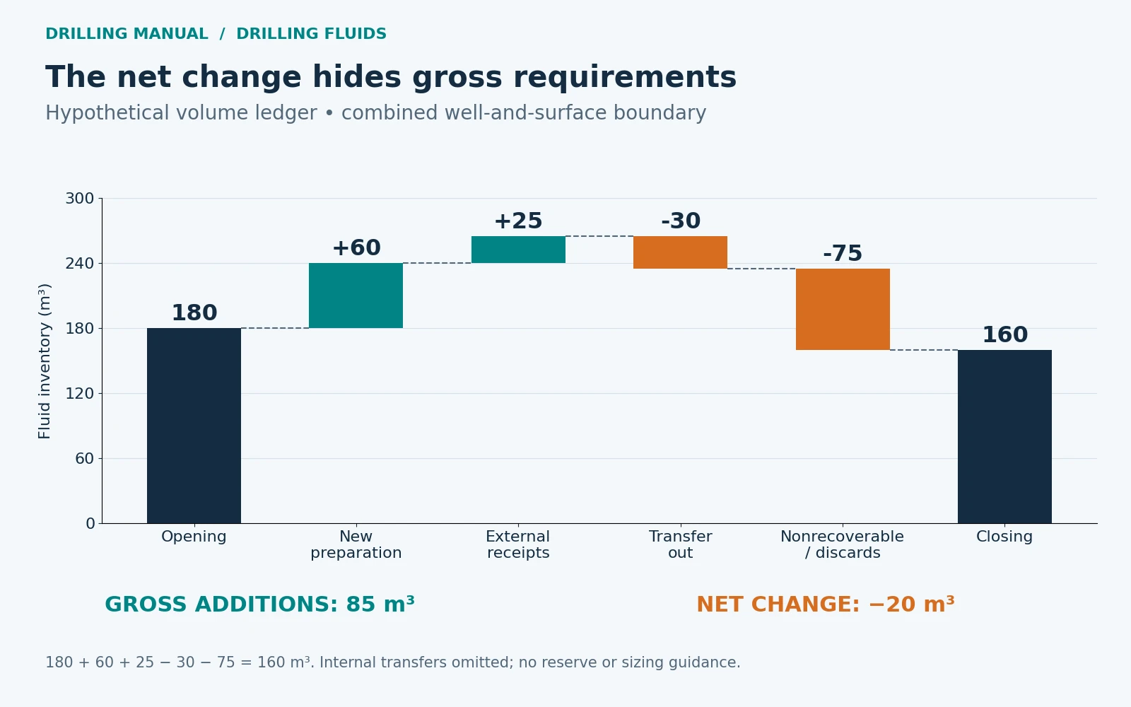
AVA includes materials and volume estimates by interval. Make that estimate auditable by declaring the inventory boundary and keeping additions, external transfers and quantities leaving the boundary separate. Internal movement between included tanks is not another receipt. [1, p. 298]
The following original example uses a hypothetical combined well-and-surface fluid inventory. All quantities are on the same volume basis. It illustrates accounting only; it does not calculate the volume needed to fill a particular well or establish a contingency reserve.
| Planned movement | Volume, m³ | Ledger treatment |
|---|---|---|
| Opening inventory | 180 | Starting quantity |
| New fluid prepared | 60 | Addition |
| External fluid received | 25 | Addition |
| Fluid transferred to another location | 30 | Deduction |
| Planned nonrecoverable volume and discards | 75 | Deduction; its detailed basis needs separate records |
| Calculated closing inventory | 160 | 180 + 60 + 25 − 30 − 75 |
A net decrease of 20 m³ does not mean that no new fluid was required: the plan includes 85 m³ of new preparation and external receipts. Nor does the 75 m³ deduction imply that all of it is loss into a formation. Its components must be identified. Keep this forecast separate from the actual daily reconciliation and explain subsequent deviations.
Connect the drilling fluid program with logistics
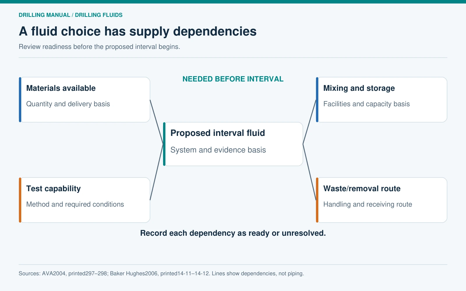
Fluid availability depends on more than the calculated volume. AVA includes transport, remoteness, weather, base-fluid and chemical availability, bulk handling, mixing equipment, testing facilities and storage among selection considerations. List the constraints that apply to the actual location rather than assuming a preferred system can be supplied at the required time. [1, p. 297]
For each important material or service, identify the forecast need, available stock, delivery basis, storage location, responsible party and unresolved dependency. Keep package units and active-product quantities distinct. The template provides fields for that information but no invented consumption rates or mandatory stock margins.
Include the solids-control arrangement and the route for fluid or solids leaving the useful inventory. A program that can deliver fresh mud but cannot store, recover or remove the displaced material has left a practical dependency unresolved. Baker Hughes connects fluid planning with waste segregation, logistics and performance reporting. [2, pp. 14-11–14-14]
Write contingencies as decisions with evidence
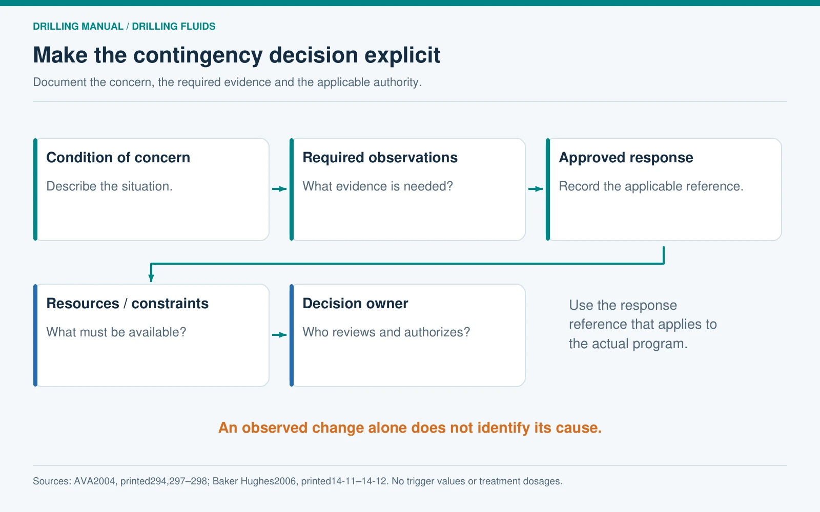
The drilling fluid program should anticipate credible departures from its assumptions. AVA explicitly includes contingency planning, while Baker Hughes describes identifying technical and logistical obstacles and establishing tracking protocols. These sources support preparation before a problem arises; they do not justify publishing one treatment recipe for every well. [1, pp. 294, 297–298] [2, pp. 14-11–14-12]
For each drilling fluid program contingency, record the condition of concern, the observations needed to confirm it, the approved response reference, required materials or equipment and the person responsible for the decision. The response may still need a specialist review. “Add treatment” without an identified basis or authority is not a complete contingency entry.
Keep the trigger separate from the diagnosis. A changed fluid property can prompt investigation, but the same observation may have more than one explanation. The planning record should identify what information is needed before choosing among the applicable approved responses.
Maintain a clear revision and handover record
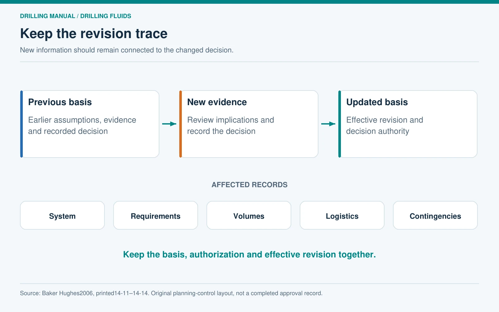
A change to the drilling fluid program can affect more than one table. If new evidence changes an interval assumption, review its effect on the proposed system, testing, volumes, logistics and contingencies. Record the old basis, the new evidence, the decision, the authorizing record and the effective revision. Do not leave the obsolete target appearing current in another sheet.
Baker Hughes describes capturing changes and lessons during execution and using the results in future planning. Apply that principle through a concise change record and a final comparison of the intended plan with what occurred. The objective is a traceable decision history, not a file containing several unexplained versions. [2, pp. 14-11–14-14]
Frequently asked questions
Who prepares a drilling fluid program?
AVA describes preparation with the operator’s geology and engineering teams, either by the operator or with a service company. The document should identify responsibility for its inputs, technical review and acceptance under the actual project’s arrangements. [1, p. 297]
Is a mud-property table enough?
No. The reader also needs the interval objectives, design inputs, testing basis, materials and volume estimates, equipment constraints and contingencies. Those subjects explain why the proposed properties matter and how the fluid plan can be supported. [1, pp. 294–298]
Must every interval use a different fluid?
No. AVA considers continuity of the fluid system as one possible advantage, alongside each interval’s demand criteria. Continued use, conversion and replacement should be evaluated against those criteria instead of being assumed from the casing boundaries alone. [1, pp. 294, 297]
Does one passing laboratory result qualify the system?
It addresses the requirement represented by that test and its conditions. The manuals describe multiple assessment needs, especially for reservoir drill-in fluids. Keep remaining requirements and limitations visible before accepting the full proposal. [1, p. 296] [2, pp. 1-34–1-36]
Does the planning template include recommended mud targets?
No. The engineering-target fields remain editable and unfilled. The only numerical example is an explicitly hypothetical volume balance. Enter the actual well’s justified requirements, methods and acceptance references through the responsible design and review process.
How does the program differ from the daily mud report?
The program states the intended objectives and arrangements; the daily report records measurements, movements and activities during execution. A change to the plan needs its own recorded basis and revision. Actual results should remain identifiable as observations.
References
- AVA S.p.A. Drilling Fluids Manual, Version 1, November 2004. Chapter 10, “Fluid Design.” Printed pages: 293–298. PDF pages in the edition consulted: 295–300.
- Baker Hughes Drilling Fluids. Drilling Fluids Reference Manual, revised 2006. Chapter 1 reservoir drill-in screening and program discussion; Chapter 14 planning and execution discussion. Printed pages: 1-34–1-36 and 14-11–14-14. PDF pages in the edition consulted: 41–43 and 667–670.