Solids control is a constant problem, every day on every well. Generally, we can define solids control as controlling the quantity and quality of undesired cuttings in the drilling mud types since the increasing of these solids can generate negative effects both to the well and drilling. In addition, these solids will increase the total mud cost and further the cost of oil and gas wells.
Solids in Drilling Mud Problem
Generally, mud additives (OBM additives – WBM additives) and drilling cuttings are the major sources of solids. Formation cuttings are contaminants that degrade the performance of the drilling fluid. If we didn’t remove the cuttings, drill string & drilling bit rotation would grind them into smaller and smaller particles that become more difficult to withdraw from the drilling fluid. One of the primary uses for drilling fluid is to carry unwanted drilled solids from the borehole. These solids are contaminants and can lead to numerous operational problems if left in the mud.
Solids can be distinguished in two categories:
- Low Gravity Solids (LGS) with a specific gravity range of 2.3 to 2.8 S.G.
- High Gravity Solids (HGS) with S.G. of 4.2 or more.
Three options are available to maintain acceptable drilling fluid properties:
- Firstly, do nothing and let the solids build up. When the mud no longer meets specifications, throw it away and start with fresh drilling fluid.
- Secondly, dilute and rebuild the system to keep the mud properties within acceptable ranges while dumping excess fluids into the reserve pit.
- Thirdly, lower the drilling fluids’ solids content through solids removal to minimize the addition/dilution necessary to maintain acceptable properties.
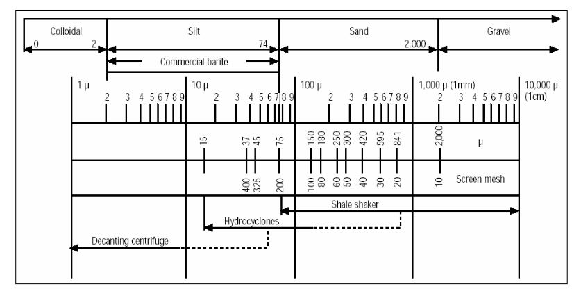
Solids Sizes
On the drilling rig, we can remove most formation solids by mechanical means at the surface. Small particles significantly affect drilling fluid properties more than large particles. This effect is because small particle removal is challenging. The drilling cuttings sizes can range from 1 to 250 microns. The following table lists the approximate sizes of contaminating solids.
| Material | Diameter (microns) | Screen Mesh Required to Remove |
| Clay Colloidals | 1 | – |
| Bentonite | 5 | – |
| Silt | 6-44 | 1,470 – 400 |
| Barites | 6-45 | 1,470 – 401 |
| Fine Cement Dust | 6-46 | 1,470 – 402 |
| Fine Sand | 44 | 325 |
| 53 | 270 | |
| 74 | 200 | |
| API Sand | 105 | 140 |
| 149 | 100 | |
| Coarse Sand | 500 | 35 |
| 1,000 | 18 |
The following table details the standard particle size classification:
| API Class | Size Range (microns) | Common Term | Screen Mesh |
| Coarse | >2000 | Sand | 10 |
| Intermediate | 250 – 2000 | Sand | 60 |
| Medium | 73 – 250 | Silt | 210 |
| Fine | 44 – 73 | Silt | 460 |
| Ultra Fine | 2 – 44 | Clay | – |
| Colloidal | 0 – 2 | Clay | – |
Solids Volume While Drilling
We may use the following equation to estimate the volume of solids entering the mud circulation system while drilling:
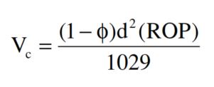
Where,
- Vc= volume of cuttings (bbl/hr)
- d = hole diameter (in)
- φ = average formation porosity
- ROP = rate of penetration (ft/hr)
Thus for a typical North Sea well (d = 26″, ROP = 62 ft/hr, φ = 0.25)
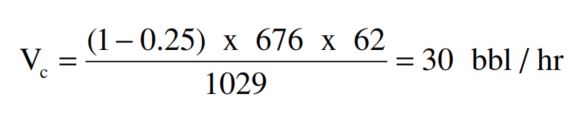
Therefore 30 bbls of solids must be removed by the solids control equipment every hour.
Simple Rule
Based on the above, We must remove solids to allow efficient drilling to continue without increasing mud costs. However, We should retain some particles in the mud (e.g., Barite, Bentonite) since they are required to maintain the properties of the drilling fluids. If we remove these desirable solids, we must replace them with more surface additions, increasing the mud cost.
Solid Control Benefits
Solids control is the most expensive part of the mud system since it operates continuously to remove unwanted solids. It is generally cheaper to use mechanical devices to reduce the solids content rather than treat the mud with chemicals once the solids have become incorporated into the drilling fluid.
We usually describe the solids which do not hydrate or react with other compounds within the mud as “inert.” These may include sand, silt, limestone, and barite. In addition, we consider all of these solids (except barite) to be undesirable since:
- Firstly, they increase frictional resistance without improving lifting capacity.
- Secondly, these solids will form a filter cake. This cake tends to be thick and permeable, leading to drilling problems. (stuck pipe, increased drag) and possible formation damage.
- Thirdly, solids also cause damage to the mud pumps, leading to higher maintenance costs.
Using solids removal to minimize addition/dilution volumes is usually the most effective and provides the following benefits:
- Increased penetration rates (Factors affecting penetration rates (ROP))
- Reduced mud costs
- Lower water requirements
- Reduced torque and drag
- Less mixing problems
- Reduced system pressure losses
- Lower circulating density (ECD)
- Better cementing in drilling
- Reduced instances of lost circulation
- Reduced formation damage
- Less differential sticking
- Reduced environmental impact
- Less waste, lower disposal costs
Poor Solid Control Consequences
The consequences of poor solids control:
- Stuck pipe
- Reduced Drilling rate
- Thick Filter cake
- Increased Drilling Fluid Dilution
- Increased Chemical consumption
- Increased Torque and Drag
- Formation Damage
- Problems with well Evaluation
- Poor cement jobs
- Increased surge/swab pressures (Swab And Surge In Drilling Definition & Calculations), ECD
- Increased equipment wear and tear, decreased bit life
Economic Impact Of Solid Control
Penetration Rate
Ideally, figure 1 shows the impact of solids control on penetration rate. This has become a classic illustration of the benefits of a low solids content mud. For example, a reduction in average solids content from 4.8% (9.0 ppg) to 2.6% (8.7 ppg) results in a 15% reduction in total rig days.
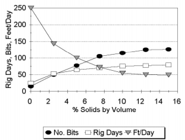
In soft rock countries like the Gulf Coast, efficient solids removal can reduce the need to control drills by limiting required dilution rates to manageable levels and reducing operational problems due to overloaded solids removal equipment.
Dilution Rate
Solids removal efficiency directly impacts dilution costs. The dilution of water will incur three charges simultaneously:
- Dilution water cost.
- Cost of additives to maintain stable mud properties.
- Disposal cost.
While actual, We can’t predict the savings due to improved penetration rates and reduced trouble time as justification for improved solids control equipment. In many cases, however, the economic advantages of reduced dilution and disposal costs are more than enough to justify.
The Major Role
It is apparent from this list that the role of solids control is instrumental in the maintenance of a superior drilling fluid. Solids control equipment has been standard hardware on most rotary drilling rigs since the early 1960s. Many solid/liquid separation devices were borrowed from other industries in the early years and applied directly to oilfield rotary drilling. Although the basic operating principles and techniques associated with mechanical solids removal have not changed significantly over the years, refinements in design specifically for drilling applications have yielded considerable improvements in performance and reliability.
Methods Of Solid Control While Drilling
For most practical purposes, oil and gas companies divide the mud solids into two groups according to their density:
- Low gravity solids s.g. = 2.5 – 3.0
- High gravity solids s.g. = 4.2 (barite).
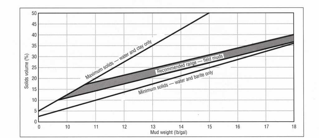
Remember that drilling mud will contain different proportions of each solid (e.g., to maintain hydrostatic mud pressure, we must add high-gravity solids, so this type of mud should contain fewer low-gravity solids). Solids control in fluids containing barite (weighted muds) requires special procedures to ensure that there is no discarding for barite along with undesirable solids. Drilling Fluids containing low gravity solids only (unweighted muds) have a density of 8.5 – 12 ppg.
There are three basic methods used to control the solids content of a drilling fluid:
- Dilution
- Gravity Settling
- Mechanical Devices Screening
- Forced Settling
Dilution
After passing through all screening and settling stages, there will still be a very fine-solids content that remains in the mud. This mud can either be discarded or diluted. We usually discard some drilling fluids (together with desirable solids and other chemicals) before the remainder can be diluted and conditioned for re-circulating. The reason for that is the limited capacity of the active system,
Mud engineers can dilute oil-based mud with a base oil (or clean oil mud), and they can dilute water-based mud with water (or clean water mud) to keep the concentration and surface area of solids within bounds. Two approaches for dilution are:
- Continuously dump and dilute while drilling. This method is the most expensive approach to solids control in most situations.
- Dump periodically and dilute while drilling. This method is more cost-effective than the first approach. We can apply certain practices to make it less costly.
The total costs of dilution are the cost of the water hauled to the rig, the cost of converting that water into the mud with the correct density, and the cost of disposal of the dumped drilling fluid. Follow these practices to make dilution less expensive:
- Minimize the total volume of mud that we require to dilute.
- Dump (displace) the maximum possible dirty fluids before adding water and materials, and
- Dilute as much as possible in a single step- not a series of small dilutions.
Therefore, as mud becomes more expensive with time, dilution becomes a less attractive option, and we should pursue mechanical separation.
Gravity Settling
In locations where we can build large, shallow earthen pits, we can circulate mud through the tanks, allowing settling out of drill solids. It is a rare situation today when we can do this, but it is an alternative solution. On drilling rig types with steel pits, the sand trap (under the shale shaker) is the only place where settling should occur.
For the natural settling of solid particles under laminar conditions, Stokes Law applies:
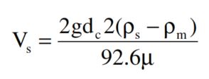
Where:
- Vs= slip or settling velocity (ft/sec) – Check also: Annular Velocity Formula, Calculations and Function.
- g = acceleration due to gravity (ft/sec2)
- dc= largest cutting diameter (ft)
- ρm= mud density (lb/ft2) – You may be interested in Mud Balance Test Procedure | Pressurized & Tru-Wate.
- ρs= cutting density (lb/ft2)
- µ = mud viscosity (cps) – (Related subjects: Rheometer Test Method | Drilling Fluid Viscometer & Marsh Funnel Viscosity Test Procedure).
Basically, the solids will settle out more readily when:
- The solid particles are large and heavy.
- Utilization of mechanical devices that increase the gravitational force.
- The mud is light and has a low viscosity.
Mechanical Settling Devices
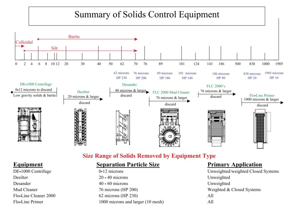
Generally, we can group equipment that removes solids mechanically into two major classifications:
- Screen Devices
- Centrifugal Separation Devices.
The following table identifies the particle sizes (in microns) the equipment can remove.
| Solids Control Equipment | Particle Sizes Removed |
| Screen Devices | 61-micron cut with 250 mesh screen |
| Decanting Centrifuges | Colloidal Solids to 5 microns |
| Hydrocyclones | 20-70 micron solids, depending on cone size |
removed depends on the type of solids control equipment.
Screening
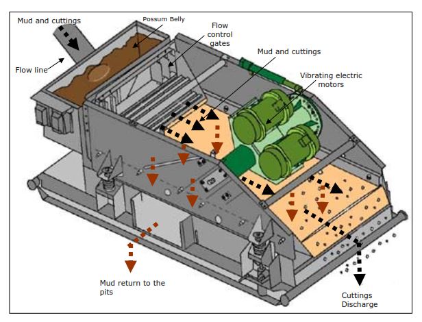
The most common screen device is a shale shaker, which contains one or more vibrating shaker screens that mud passes through as it circulates out of the hole. And further, separate the solids according to size and discard the material too large to pass, while the finer material will undergo further treatment. We can classify the shale shakers as circular/elliptical or linear motion types. You can find more about its design in Shale Shaker Design & Performance.
- Circular/elliptical motion shaker. This shaker uses elliptical rollers to generate a circular rocking motion, providing better solids removal through the screens.
- Linear motion shaker. This shaker uses a straightforward and back rocking motion to keep the fluid circulating through the screens.
Centrifugal Separation Devices.
When the viscosity of the mud is increased (to improve lifting capacity), solids settling becomes more difficult. The natural settling rate is far too slow for practical purposes, so mechanical devices are introduced to remove the solids. Hydrocyclones and centrifuges increase the gravitational force on the solid particles. And further separate the denser particles from the lighter fluids. That’s why we sometimes call this process “forced settling.”
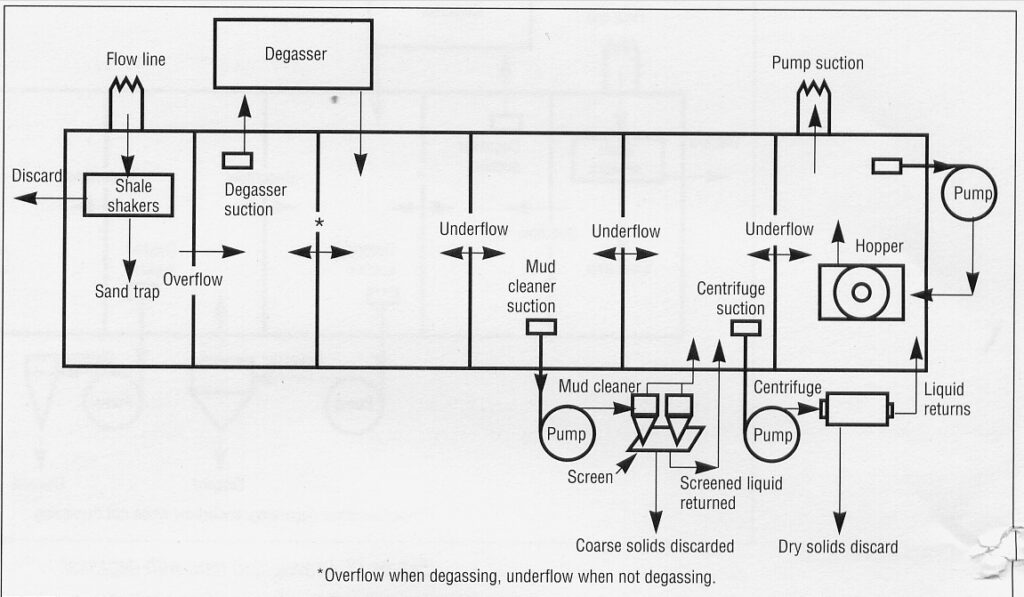
These solid control devices include all hydroclone, Desanders, Desilters, etc., and centrifuges. Mud cleaners combine the screen and centrifugal separation principles.
The following table identifies the particle sizes (in microns) the equipment can remove.
Solids Control Equipment
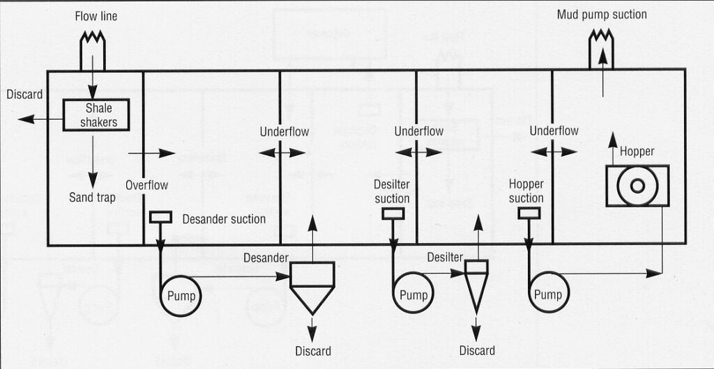
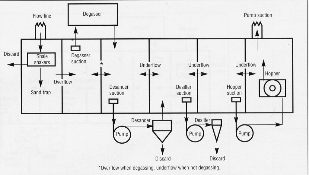
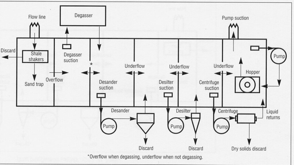
We can say that the primary solids control equipment in the oil & gas industry are as follows:
- Shale Shakers
- Desanders & Desilters – Hydrocyclone
- Centrifuges
- Mud Cleaner
We have discussed them in more detail in our previous solid control equipment post.
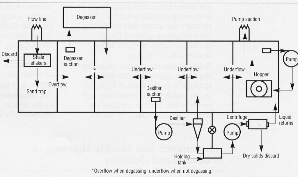
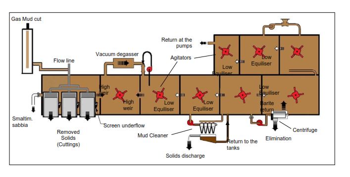
Solids Control Systems