A float shoe and float collar are casing-cementing components that contain one-way valves to help stop cement or wellbore fluids flowing back into the casing after displacement. A float shoe sits at the casing bottom and guides it past borehole irregularities; a float collar is installed above the shoe and commonly supplies a landing seat for cementing plugs. The two components are not interchangeable in every cementing arrangement.
A guide shoe does not necessarily contain a check valve. Automatic-fill and differential-fill equipment describe how the float mechanism allows casing filling during running, not completely separate types of cementing operation. Selection depends on casing geometry, expected surge pressures, fluid type, valve conversion requirements, circulation rate, and the approved cementing program.
Float Shoe vs Float Collar: Quick Comparison
| Equipment | Where installed / principle | Main purpose | Key limitation |
|---|---|---|---|
| Guide shoe | Bottom of casing; rounded guide without a float valve in its basic form | Guide casing past ledges; offer fluid outlet | Does not itself provide a backflow check valve |
| Float shoe | Bottom of casing with one-way valve | Guide casing and resist reverse flow after cement displacement | Valve can leak, become obstructed or require filling procedure |
| Float collar | In casing above the shoe; often contains a valve and plug-landing seat | Receive cement plugs, provide backflow control and establish shoe track | Placement and compatibility with plugs are design-specific |
| Automatic-fill float equipment | Shoe or collar that admits fluid during casing run; later converted to checking mode | Reduce the need for repeated surface filling and manage running conditions | Conversion mechanism and flow limits vary by product |
| Differential-fill float equipment | Shoe or collar with a controlled fill response to pressure difference | Help avoid excessive differential across a partly empty casing string | Opening thresholds and conversion must be verified for actual tool |
For the wider casing-running sequence, see casing running procedures and the pre-cementing casing checklist.
How Float Equipment Works During Casing Running and Cementing
- Run the casing: the nose guides the lower joint. With conventional check valves, the running crew must maintain the planned filling procedure; approved automatic-fill configurations allow controlled entry of wellbore fluid.
- Condition and circulate: forward flow from inside the casing through the float system and shoe establishes a flow path into the annulus, subject to the device’s rated flow and pressure limits.
- Launch and pump cementing plugs: where a two-plug system is used, the bottom plug separates mud and slurry, and the top plug follows the cement. The float collar or compatible landing equipment provides the designed plug seats. For the surface launch equipment, see cementing heads and plug containers.
- Displace and bump: a pressure response may indicate the landing of the top plug, but it must be interpreted with the verified displacement schedule, plug system, and well conditions.
- Release pressure and observe backflow: the float valves should oppose reverse flow, but check-valve performance must be verified by the procedure; unexpected returns require the preplanned contingency and safe pressure management.
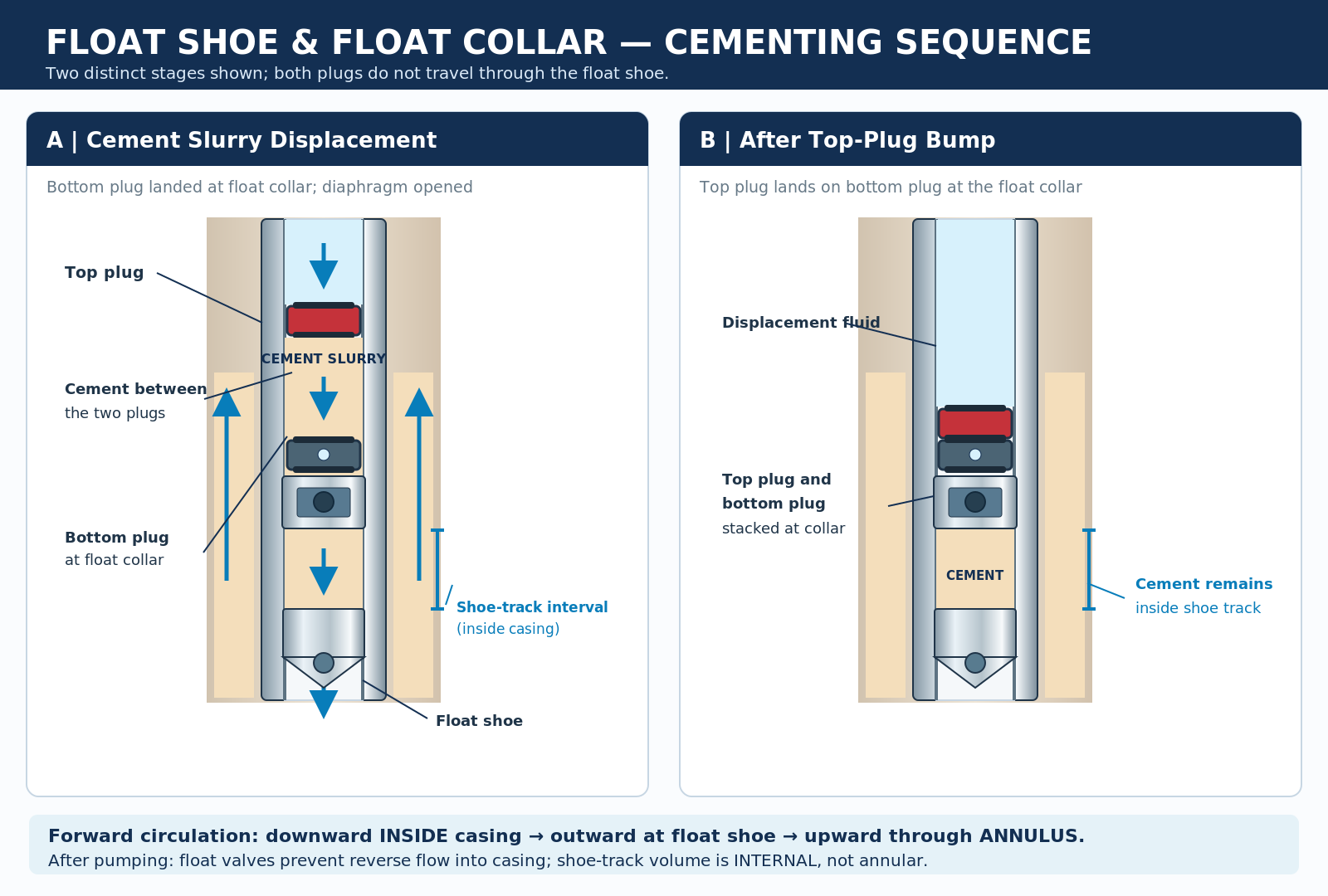
A float valve is a one-way-flow device; do not automatically treat it as a tested independent well barrier. The operator’s barriers, displacement limits, and float verification procedures govern the job. Learn the sequence in single-stage cementing and displacement and cementing wiper plugs.
Guide Casing Shoe
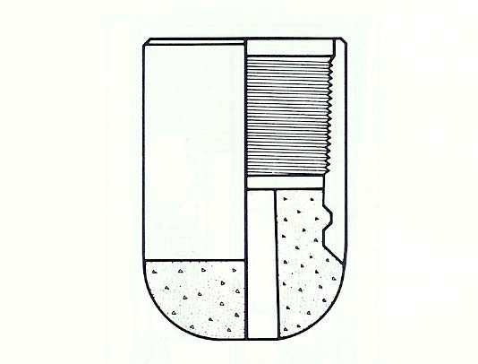
A guide shoe has a rounded, typically drillable nose attached to the lower end of a casing string. Its geometry helps the string negotiate minor borehole irregularities. A simple guide shoe permits fluid passage but has no integral non-return valve. A float shoe adds that backpressure function.
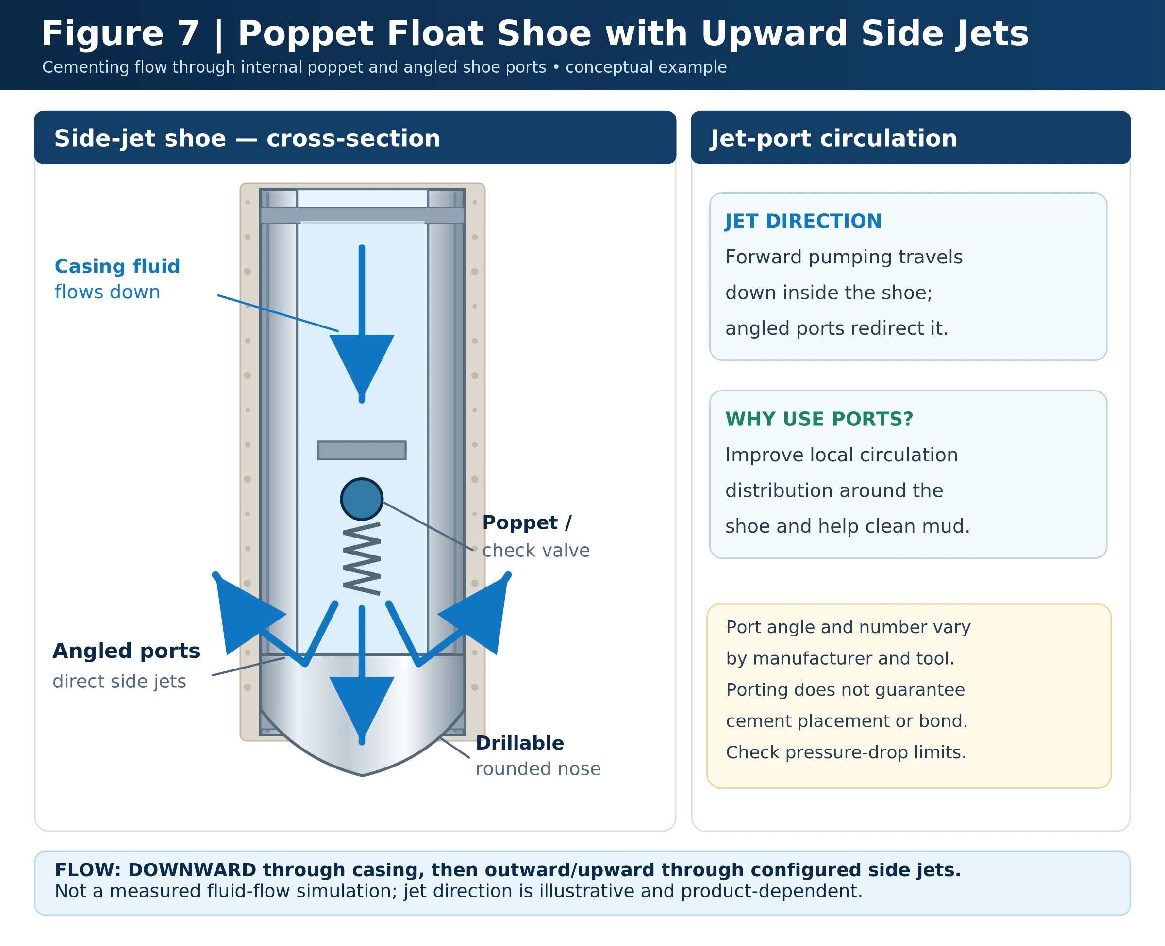
The nose material and available flow outlets vary by design. Some products have a central port or additional side ports to distribute circulation around the shoe; the actual outlet area and erosion limits must be confirmed before establishing pumping rates. See the dedicated guide shoe guide.
Float Shoe: Check-Valve Mechanisms
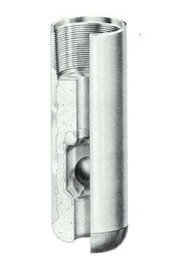
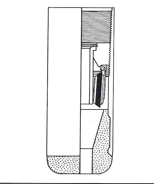
A float shoe combines the guiding nose with a backpressure valve that permits intended forward flow from casing to annulus and opposes reverse flow. The purpose is especially important after cement displacement, when a hydrostatic pressure imbalance between the slurry in the annulus and fluid inside the casing may encourage cement to return through the shoe. A second float device above the shoe may provide additional reliability, subject to the installed configuration.
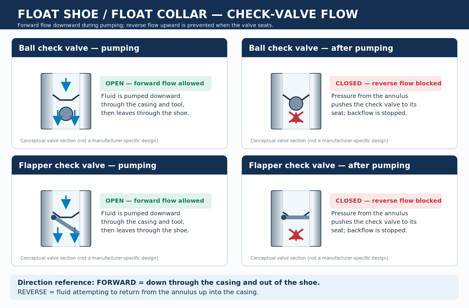
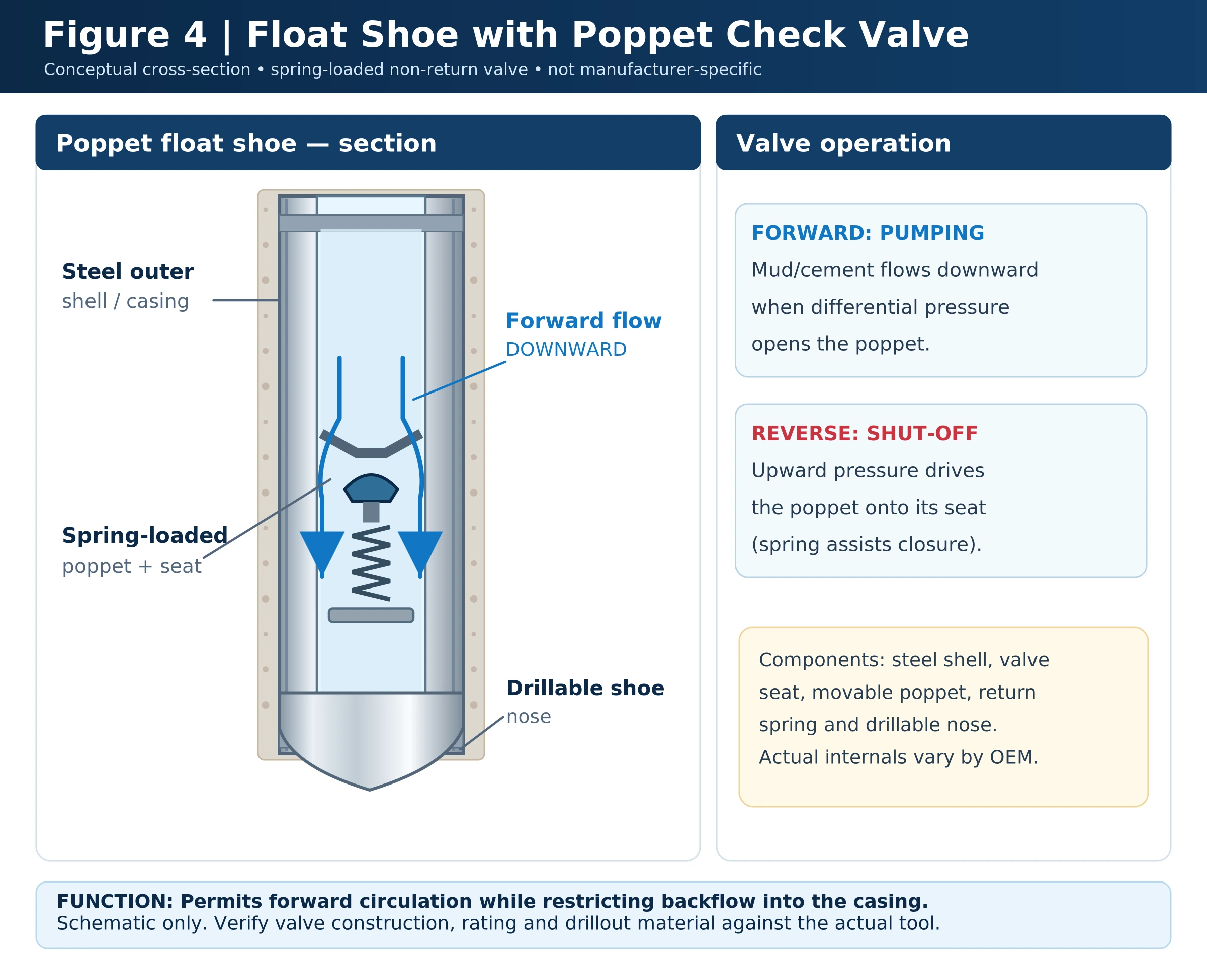
Conventional check-valve designs include ball, flapper and poppet arrangements. No single valve family is inherently the most reliable in all drilling fluids and conditions. Performance also depends on seat integrity, debris, temperature, pressure rating, flow rate and qualification testing.
| Valve mechanism | Operating concept | Points to verify |
|---|---|---|
| Ball | Ball moves to or from a valve seat to control the direction of flow | Ball/seat compatibility, orientation and debris sensitivity |
| Flapper | Hinged closure moves away under forward flow and returns toward its seat under reverse differential | Hinge, spring where provided, erosion and seal condition |
| Poppet | Axially moving closure returns onto a seat against reverse flow | Spring/seat design, flow capacity and solids tolerance |
Automatic-Fill Float Shoes and Collars
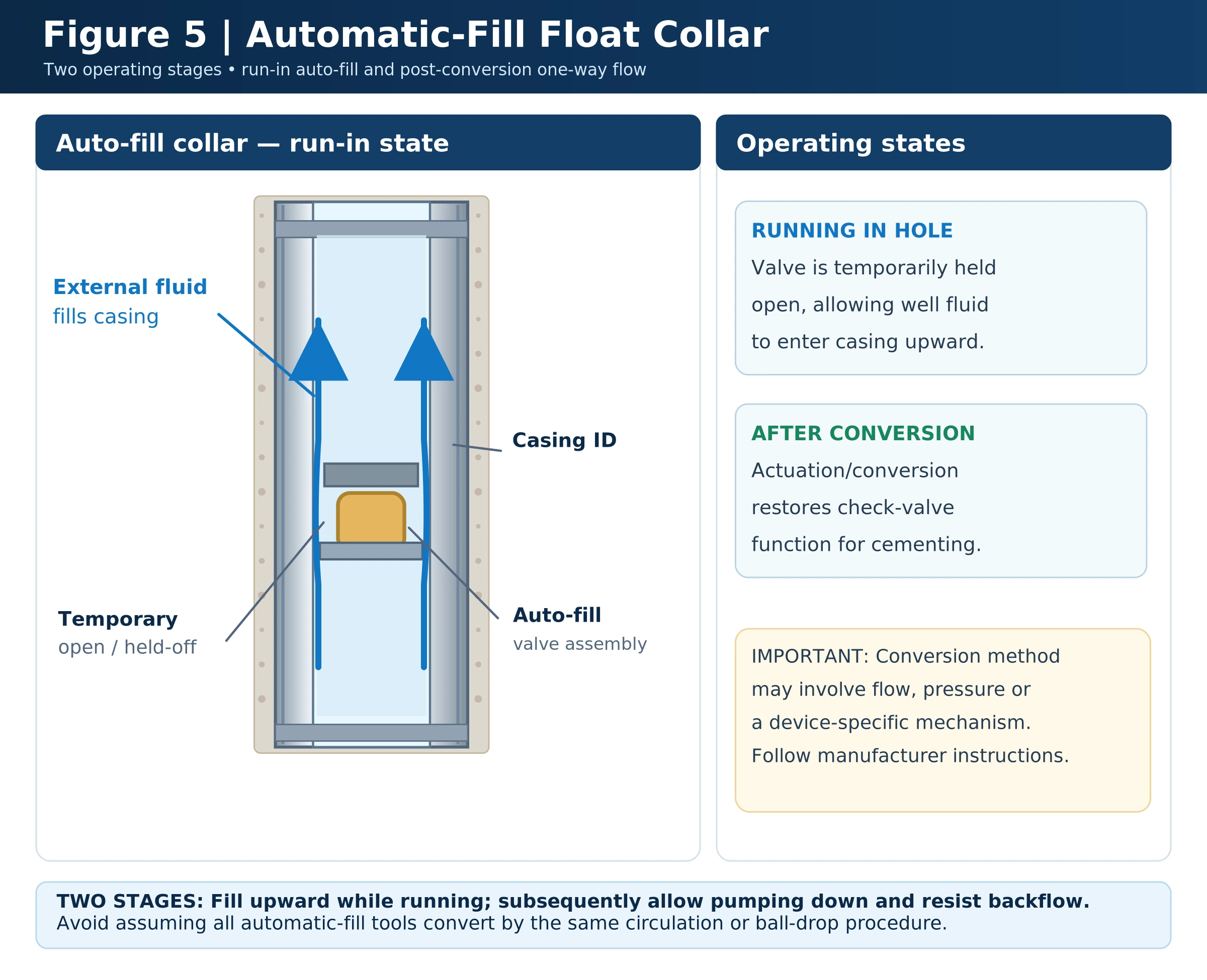
Automatic-fill equipment is intended to allow controlled entry of wellbore fluid into the casing while it is being run, helping limit the differential pressure that could develop in a comparatively empty casing string and reducing repeated surface-fill interruptions. The device later transitions to its intended non-return function by a product-specific conversion sequence, which may involve flow rate, pressure, ball/dart actuation or other mechanical arrangements.
A critical planning check is whether the tool has actually converted before cement displacement. The required conversion rate or pressure and any restrictions during circulation must come from the manufacturer’s instructions—not from a generic setting in a handbook. Early or incomplete conversion can affect fill behaviour, surge control or the subsequent float check.
Differential-Fill Type Float Equipment
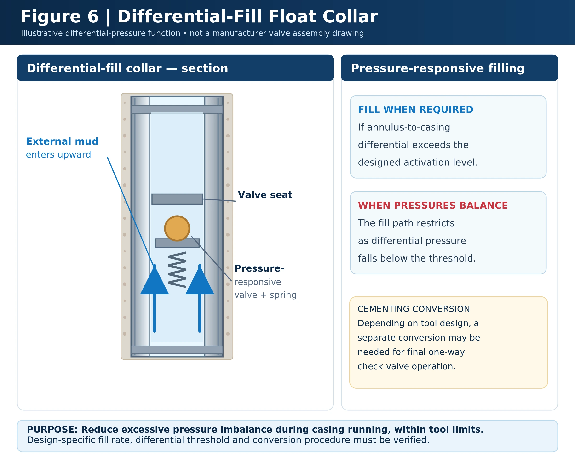
Differential-fill devices admit fluid into the casing when a specified pressure-difference condition is reached. Depending on the design, the valve arrangement then limits entry or converts to conventional float behaviour at the approved point in the operation. This feature can help control the running differential, but it does not remove the need to model surge/swab loads or confirm casing-fill status.
The differential opening and closing thresholds are equipment-specific; do not assume a universal value or rely on the tool as the sole safeguard against collapse or lost circulation. Verify the planned conversion, pumping-rate restrictions and tool operating envelope before running casing.
Some float shoes use directional side ports or jets in addition to a nose outlet. Their function is to influence fluid distribution near the shoe, but better cement displacement cannot be assumed without considering hole geometry, stand-off, mud removal, and compatible flow rate. The selection and spacing of casing centralizers help determine casing stand-off during cementing.
Float Collars, Cementing Plugs and Shoe Track
A float collar is generally installed one or more casing joints above the bottom shoe. It may contain its own check valve and often provides a compatible landing assembly for cementing plugs. The shoe track is the interval inside the casing between the float-collar landing point and the shoe; its purpose is to retain displaced or potentially contaminated cement away from the annular cement around the shoe.
One- and two-joint shoe tracks are familiar conventional arrangements, but the required length is a cementing design decision, not an absolute two-joint rule. Account for casing ID, displacement volumes, required cement quality near the shoe, plug-seat configuration, inner-string cementing if applicable, the planned drillout and contingency.
In some cementing assemblies, a suitable float insert can be installed within a compatible casing coupling instead of using a conventional full-length float collar. The decision requires checking connection compatibility, plug landing, flow capacity, drillout and the insert’s qualified backpressure performance. Do not assume an insert is equivalent to a float collar solely because both incorporate check valves.
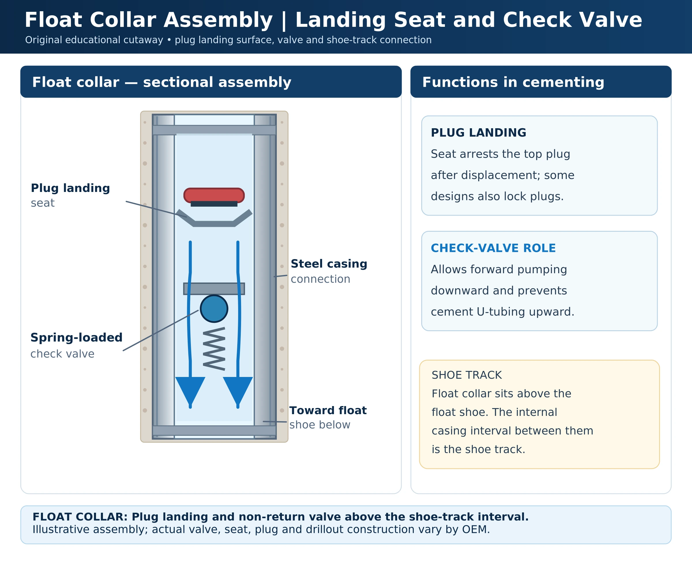
During two-plug cementing, the bottom plug commonly lands and opens to allow cement to pass through. The top plug then lands and gives the expected final pressure response (“bump”). A plug-bump pressure change indicates landing/flow restriction under the actual conditions; it does not by itself prove that the cement is correctly placed throughout the annulus.
Worked Example: Float-Collar Shoe-Track Capacity
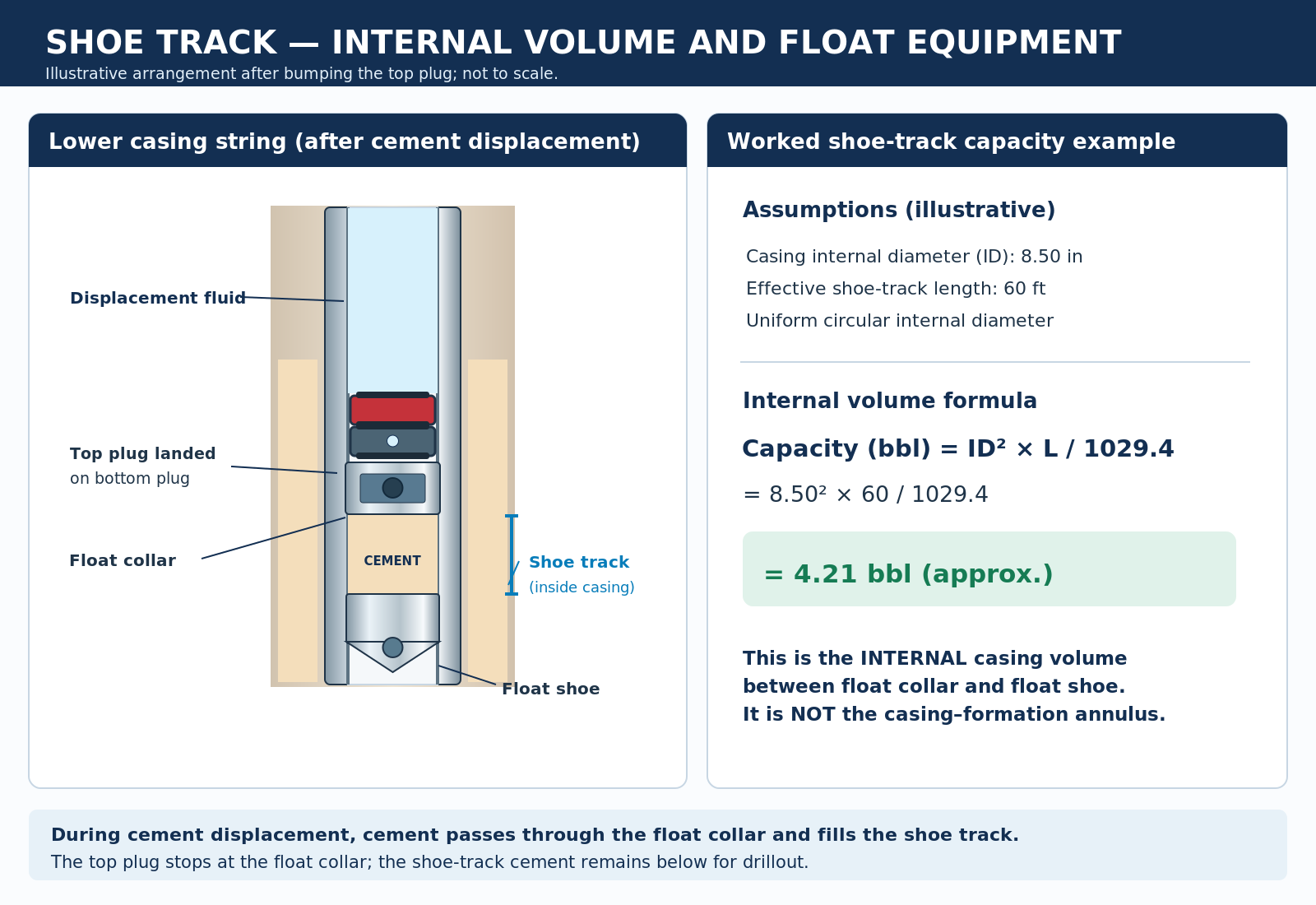
Illustrative case only. Assume a 60-ft shoe track with a uniform 8.50-in casing internal diameter. Its approximate internal volume is the cylindrical capacity of the interval:
Capacity (bbl/ft) = ID² / 1,029.4, with ID in inches. Therefore shoe-track volume = (8.50² / 1,029.4) × 60 ≈ 4.21 bbl.
For the detailed whole-job volumes—including slurry, annulus, spacer and displacement—see casing cementing calculations and spreadsheets.
This is the nominal internal volume of the shoe track, not an extra 4.21 bbl automatically added to the full planned cement-displacement volume. Plug landing depth, displacement endpoint, casing drift/ID, tool internal volume, and shoe-track cement quality must be treated consistently in the cementing calculations. For other sizes, use pipe capacity and displacement calculations.
The example highlights a design trade-off: more shoe-track length increases internal capacity retained below the collar and may provide a buffer for interface contamination, but also increases material to drill out and can change the cement program. No fixed number of casing joints is suitable for every string. For a separate discussion of equipment removal during subsequent drillout, see drilling float collars and shoes with a PDC bit.
Float Equipment Selection: Pre-Job Checklist
| Review item | Engineering question / acceptance basis |
|---|---|
| Casing geometry | Do casing size, connection, drift ID, float-tool OD, and cementing plugs match? |
| Operating limits | Are differential pressure, temperature, casing-load, flow-rate and erosion limits documented for the selected tool? |
| Fluid compatibility | Is the valve suited to the actual drilling fluid/cement system, including solids, chemistry, and expected temperature? |
| Fill conversion | For auto/differential fill, how will conversion or valve status be verified before cement displacement? |
| Shoe-track geometry | Does the collar location provide the intended length and cement volume without sacrificing planned clearance? |
| Well-control and contingency | What is the approved action if the float fails its check or permits persistent backflow? |
| Quality assurance | Are manufacturer certificates, correct valve configuration, inspection and required tests available? |
For the complete operation, coordinate float selection with casing cementing design and primary cementing operations.
Float Equipment Failure: Symptoms, Causes and Engineering Response
Float valves can fail to check reverse flow, convert at the wrong point, fail to open sufficiently for circulation or become partially obstructed. Do not assume that every unexpected return is a failed float: displacement error, trapped fluid, thermal or elastic effects, incomplete valve conversion, and pressure measurement issues can produce misleading symptoms.
| Observed condition | Possible explanations | Planning / diagnostic focus |
|---|---|---|
| Unexpected backflow when surface pressure is released | Valve-seat leakage, debris, incomplete conversion or hydrostatic imbalance | Confirm returns and pressures per approved float-check and well-control procedure |
| Unexpectedly high circulating pressure | Restricted float ports, closed valve, solids obstruction or unrelated line/BHA restrictions | Review valve conversion status and full hydraulic pressure budget |
| Insufficient casing fill during running | Fill valve not admitting flow, blockage, incorrect fill procedure | Review internal fluid level, differential pressure and running limits |
| Early conversion / reduced flow capacity | Wrong circulation/activation sequence or tool condition | Verify tool-specific operation, qualifications and operating envelope |
| Plug does not bump as expected | Incorrect displacement, damaged/incorrect plug, bypass, pressure-system response or landing issue | Reconcile volume/strokes and evidence without assuming cement placement |
Where reverse flow is confirmed, pressure-holding and bleed-off decisions must follow the operator’s approved well-specific cementing and well-control contingency. It can be unsafe to prescribe a universal instruction such as “hold pressure until cement gels”: sustained internal pressure may affect casing and cement-sheath stress, while uncontrolled returns may present a separate hazard. The required response depends on slurry transition time, equipment limitations, barriers and live well conditions.
Frequently Asked Questions About Float Shoes and Collars
What is the difference between a float shoe and a float collar?
The float shoe is at the casing bottom and combines a rounded guide with a non-return valve. A float collar is above the shoe and usually provides a check valve and cementing-plug landing arrangement, leaving a shoe-track interval between them.
Is a float shoe always required when running casing?
No universal rule applies across all well designs. Float-equipment requirements depend on the cementing method, casing string, operating envelope and the approved well program; a plain guide shoe may be used in suitable configurations.
How many joints should be between the float collar and shoe?
One or two joints are common examples, but the correct shoe-track length must be engineered for the specific casing and cement-displacement program, including contamination buffer, internal volume and drillout.
What is the purpose of an automatic-fill float shoe?
It allows the casing to fill in a controlled way during running, reducing repeated manual filling and helping manage differential loads. The valve must subsequently operate in its intended check mode according to its manufacturer-specific conversion procedure.
Standards, Technical Sources and Limitations
The engineering explanation draws on Petroleum Engineering Handbook, Volume II: Drilling Engineering (SPE, 2006), Chapter 9, especially §9.13.1 “Floating Equipment”; H. Rabia, Well Engineering & Construction (cementing hardware); and the cementing hardware/program documents in the uploaded engineering library. These are technical background sources, not substitutes for the current product manual and approved rig procedure.
For performance testing scope, see ISO 10427-3:2003, Performance Testing of Cementing Float Equipment; ISO identifies this publication as confirmed in 2022 and applicable to float equipment in water-based drilling and cementing fluids, not non-water-based fluids. API’s 2025 E&P publications catalog lists API Spec 10F, 4th edition (2018) for cementing float-equipment testing. Always verify applicable edition, equipment qualifications and project requirements.
All calculations here are simplified educational examples. Proper float selection requires manufacturer documentation, hydraulic checks, casing-string design, cement displacement calculations and operator approval.
gents
i found this very useful , and interesting
thank you for all your time and efforts
, god save you
Thanks Sir