Drill pipe or Drill collars can be unscrewed downhole by exploding a charge known as a string-shot (prima-cord folded up inside a piece of tubular plastic) inside a selected tool joint connection, just above the stuck pipe point ( check also free point calculation for stuck pipe), this operation can be described as mechanical drilling pipe back off. A connection should be selected which has been broken during the round trip (check also tripping pipe) prior to the pipe becoming stuck. Drill pipe back off operation is not difficult once you understand its procedure.
The simple mechanical drilling pipe back off procedure is :
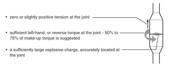
- zero or slightly positive tension at the joint
- sufficient left-hand, or reverse torque at the joint – 50% to 75% of make-up torque is suggested
- a sufficiently large explosive charge, accurately located at the joint
For a safe mechanical back off operation, carry out the following checks :
- Ensure that tong and drilling slips dies are clean, sharp and the proper size for the string above the rotary
- Check that tong, snub, and jerk lines are in excellent condition
- Also to have a safe mechanical drill pipe back off operation in drilling, you have to ensure that slip handles are tied together with strong line, to prevent the slips being kicked out of the table and thrown clear when the pipe breaks out
- Ensure that elevators are latched around the pipe and slackened off under a tool joint with the hook locked when torque is being applied to the string
- Ensuring that no torque remains in the string when it is picked out of the slips, unless the pipe is properly held with a back-up tong is important to have safe mechanical drilling back off procedure.
Particular care should always be taken when applying torque or releasing it from the string. Keep the forces involved fully under control and keep men out of the potentially dangerous area.
The following sections give information about the tension and torque to be applied when performing drilling back off operation procedure.
Note: Torque should be worked down the string before the string shot is fired, this may take some time. If the string fails to back off after firing the charge, continue to work the torque down the string before trying another string shot.
Maintaining The Appropriate Tension For successful Mechanical Drilling Pipe Back off Operations
The ideal tensile load is zero, i.e. with the threads subject to neither compression nor tension. However, since a zero tensile load is difficult to achieve, pull is applied which will develop a slight tension rather than compression. Over the years there has been some debate regarding the surface pull required to achieve this condition. Since the pipe is held down then it can be assumed that buoyancy does not affect the pipe above the stuck point. However, as soon as the joint is cracked buoyancy will act on the freed pipe.
If buoyancy does not apply then the pull required to maintain the drill pipe in tension will be the total weight of pipe above the stuck point plus the weight of other equipment such as blocks.
An alternative method for finding the required pull is to use the actual hook load observed by the Driller just before getting stuck :

In deviated wells with excessive drag and pull it will be difficult to develop the correct tension at the joint, and more than one attempt may be necessary before a successful mechanical drill pipe back-off is achieved. In a highly deviated well the pipe weight may be partially supported.
If the hook load while moving the string slowly up has been observed prior to becoming stuck, the following method can be used to estimate the required pull to have successful drilling back off procedure:
- Calculate the theoretical weight of the whole string in the air (using approximate weight for drill pipe)
- Subtract from this the observed weight of the string (hook load – blocks)
- This gives the weight loss due to buoyancy, friction, and wall support which can be expressed as a percentage.
- Calculate the theoretical weight of pipe in air down to the stuck point (using approximate weights) then subtract the percentage weight loss due to buoyancy and wall support etc.
- Add the weight of the blocks etc. and this will be the tension prior to back-off.
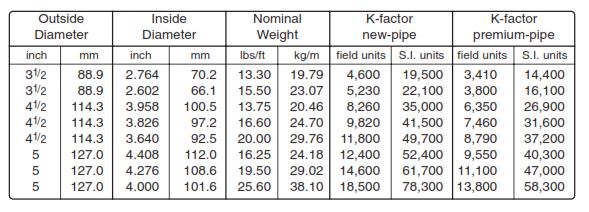
Torque Vs. Number Of Turns (Pipe Body) For The Mechanical Drill Pipe Back Off
Torque in N-m(lbs-ft) = K x turns/100m (turns/1000 ft)
where K is given in the following table:
Note :
- In S.I. units : K = 0.00051 (D4 – d4) [D and d in mm]
- In field units : K = 50.16 (D4 – d4) [D and d in inches]
These factors are based on a shear modulus of 8.274 x10¹⁰ N/m2 (11.71x 10⁶ psi)
Example For S.I. units:
127 mm IEU 29.02 kg/m, grade E, premium class drill pipe thread with NC50 tool joints. Stuck at 3,630 m
Solution:
- The approximate weight of the DP is 28.9 kg/m (download Drilling data handbook PDF)
- The weight of free pipe in air is 3,630 x 28.9 x 9.81/10 = 102,900 daN
- Using a design factor of 1.15 the allowable torque is 1,850 daN-m
- Turns per 100 m = (1,850 x 10)/ 47,000 = 0.394
- Number of turns is 0.391 x 36.30 = 14.3
Example For Non-S.I. units:
5″ IEU 19.5 lbs/ft, grade E, premium class drill pipe with NC50 tool joints. Stuck at 11,900 ft. Calculate number of turns to perform mechanical drilling pipe back off
Solution:
- The approximate weight of the DP is 19.4 lbs/ft (Download Halliburton Red Book)
- The weight of free pipe in air is 11,900 x 19.4 = 230,900 lbs.
- Using a design factor of 1.15 the allowable torque is 13,300 lbs-ft
- Turns per 1000 ft = 13,300/ 11,100 = 1.20
- Number of turns is 1.20 x 11.9 = 14.3
Note:
Remember that if the tool joint make-up torque is less than the allowable pipe body torque then when applying left-hand torque the pipe may back off before the allowable pipe body torque has been reached. If this is not desired the upper torque limit is determined by the lowest actually used tool joint makeup torque, reduced by a safety factor.
Ref: Well Engineer Notebook 4th edition