The non-magnetic drill collar is made from specially treated steel alloys so that it does not affect magnetic surveying instruments. They aim to isolate directional survey instruments from magnetic distortion due to the steel drill string.
Non Magnetic Drill Collar Function
The magnetic survey instrument is influenced by the presence of a magnetic field around the tool: ferromagnetic material in the formation, drill pipe, drill collar, or other bottom hole assemblies. This influence can’t be eliminated but can be reduced to minimize interference with the earth’s magnetic field. The survey instrument is placed inside a non-magnetic drill collar so that the survey instrument can measure the earth’s magnetic field. More than one non-magnetic drill collar may be used to minimize magnetic interference from the drill string and bottom hole assembly.
Material
Non-magnetic drill collars are manufactured from a material called Monel. This Monel contains a group of nickel alloys, mainly formed of nickel (ranging from 52 to 67%) and copper, with slight amounts of silicon, iron, carbon, and manganese. It is much stronger than pure nickel. In addition to being non-magnetic, Monel alloys have a high resistance to corrosion by highly aggressive agents, including rapidly flowing seawater. Hot- and cold-working, machining, and welding can readily be fabricated.
Non-Magnetic Drill Collar Specification & Selection
Non-magnetic drill collars are also called Monel drill collars. The location of the survey tool inside the collar and the number & length of the non-magnetic drill collars should be carefully selected. Their selection is a function of geographical location, inclination, azimuth, and bottom-hole assembly.
Earth’s Magnetic Field
The number and length of the non-magnetic drill collars needed depend upon the geographical location of the well. The location will dictate the horizontal intensity of the earth’s magnetic field and, hence, the quality of the survey reading. The horizontal intensity is relatively small, close to the earth’s poles, and is higher near the equator. A location with a low horizontal intensity would require a greater length of non-magnetic drill collars than a high intensity.
The horizontal intensity is a function of the magnetic dip angle and is given by
Horizontal Intensity = Magnetic Field Strength X cosine (Magnetic Dip Angle),
The magnetic dip angle is the angle that a magnetic needle makes with a horizontal plane at any location on the earth. This angle is close to 0o (actually -20o to 20o depending upon location) near the equator and 90o at each of the magnetic poles, and so, the horizontal intensity is highest near the equator and smallest at the magnetic poles. For example, the magnetic field strength and dip angle are 57,500 gammas and 80.6 degrees on Alaska’s North slope.
The same quantities are 48,500 gammas and 59.7 degrees in the Gulf Coast in the US. Thus, the horizontal intensity of the earth’s magnetic field is only 9,391 in Alaska but 24,470 gammas on the Gulf Coast. Hence, it will take fewer non-magnetic drill collars to survey the wellbore direction in the Gulf Coast compared to the survey on Alaska’s north slope. The stronger the horizontal intensity of the earth’s magnetic field, the less the interference from the drill string.
World Zonal Map
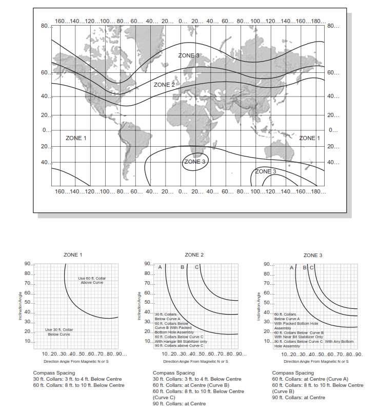
Several years ago, Shell created a zonal map of the world to describe the horizontal intensity of the Earth’s magnetic field. The intensity is strongest in Zone I, and progressively weaker in Zone II and Zone III. This zonal map is shown in Figure 1. Wellbore surveying in Zone I can be performed with fewer non-magnetic drill collars, whereas surveying in Zone III will require more non-magnetic drill collars to accurately determine the direction of a well.
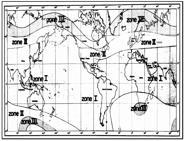
Figure 1. Map Showing the Geographical Location of the Zones for Use in Selecting Non-Magnetic Drill Collar Lengths
Inclination & Azimuth
The number of non-magnetic drill collars also depends on the inclination and direction of the well. The higher the inclination angle of the wellbore, the larger the number of drill collars required. As the direction of the wellbore is changed, additional non-magnetic drill collars may be required. Surveying a wellbore pointing to the magnetic North or South would require fewer drill collars, whereas a wellbore oriented towards the East or West would require additional collars.
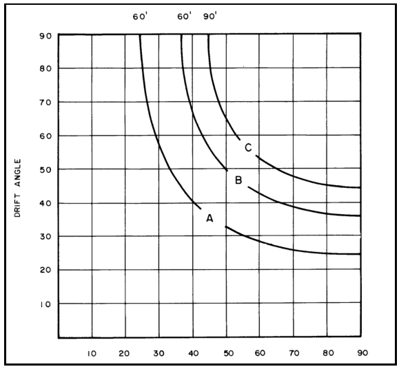
The length of the non-magnetic drill collars for the three zones can be approximated using Figures 2 through 4. Figure 1 is first used to determine the zone where the well is located. Then, the chart corresponding to this zone is utilized to select the length of non-magnetic drill collars and the compass spacing within the collars. Note that as the inclination increases for a given hole direction, the length of the non-magnetic collars required increases. Also, the collar length required increases as the direction progresses toward east or west.
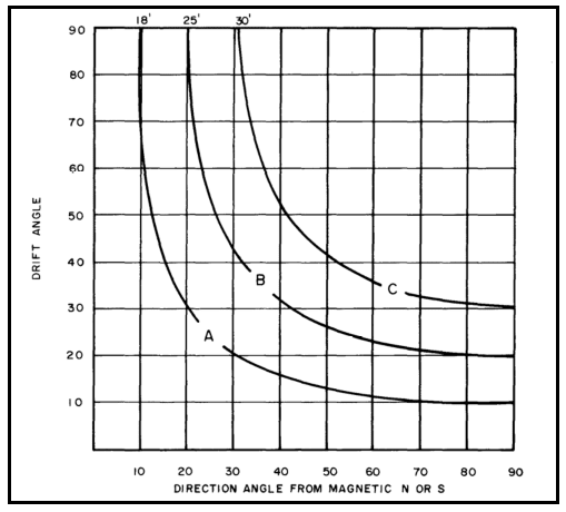
- Use 18′ collar in area below Curve A
- Use 25′ foot collar in area below Curve B
- Use 30 foot collar in area below Curve C
- Use tandem (18′ + 25′) collars in areas above Curve C
| Compass Spacing: | 18′ collar: | 1′ to 2′ below center |
| 25′ collar: | 2′ to 3′ below center | |
| 30′ collar: | 3′ to 4′ below center | |
| Tandem (18′ + 25′): | center of bottom collar |
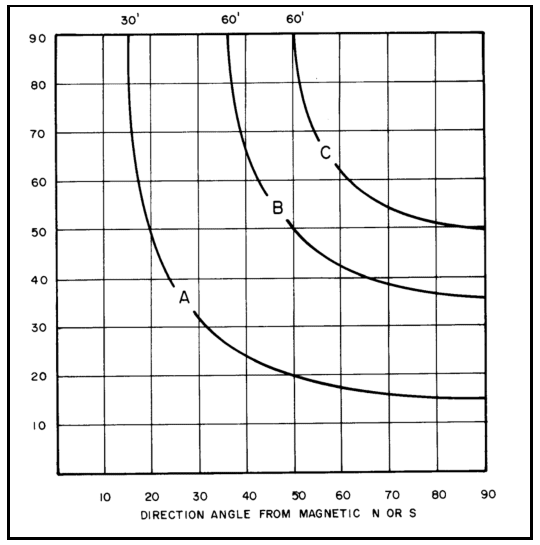
- Use 30′ collars in the area below Curve
- Use 60′ collars in the area below Curve B with packed bottom hole assembly
- Use 60′ collars in the area below Curve C with near bit stabilizer only
- Use 90′ collars in the area above Curve C
| Compass Spacing: | 30′ collar: | 3′ to 4′ below center |
| 60′ collars: | At center (Curve B) | |
| 60′ collars: | 8′ to 10′ below center (Curve C) | |
| 90′ collars: | At center |
- Firstly, use 60′ collars in the area below Curve A with packed bottom-hole assembly.
- Secondly, use 60′ collars in the area below Curve B with a near-bit drilling stabilizer only.
- Thirdly, use 90′ collars in the area below Curve C with any bottom-hole assembly.
| Compass Spacing: | 60′ collars | At the center (Curve A) |
| 60′ collars: | 8′ to 10′ below center (Curve B) | |
| 90′ collars: | At center |
Total Magnetic Field Effect
The earth’s magnetic field alone does not determine the non-magnetic drill collar length and compass spacing. It is determined by the total magnetic field, which is the vectorial sum of the earth’s magnetic field, and the magnetic field caused by the magnetized portions of the drill string. Since the drill string is much longer than its diameter, it can be analyzed as though it were a point source. In most cases, there is a North pole (+) above the non-magnetic drill collar and a South pole (-) below the non-magnetic drill collar. The pole strengths determine the non-magnetic collar length. The stronger the pole, the greater the length required. The actual pole strength depends upon the specific bottom-hole assembly component. Pole strengths can vary significantly even when comparing collars of the same size. The selection charts have assumed constant pole strengths; therefore, care should be exercised in using the charts.
Compass Spacing For Non-Magnetic Drill Collars
Generally, the upper pole strength (North) is greater than the lower pole strength (South), mainly due to the length of the drill string. The effect of the magnetic forces caused by the drill string cannot be eliminated but can be minimized. The point at which the magnetic field has a minimum effect is the optimum placement for the compass. With short bottom hole assemblies (weaker magnetic poles), the optimum compass spacing is below the center of the non-magnetic collar length. With longer bottom-hole assemblies (such as a holding assembly or downhole motor), the optimum spacing is closer to the center of the non-magnetic collar length. Non-magnetic drill collars are manufactured from a solid piece of non-magnetic steel and the ID is bored from both ends. The bore may not match exactly in the center and can cause a slight magnetic field. It is usually best not to put the magnetometers in the exact center of the non-magnetic drill collar.
Conclusion
Nonmagnetic drill collars are made from Monel, and their presence undisturbed the Earth’s magnetic field. Therefore, an accurate reading of the well’s direction can be obtained. The number of collars that are required depends on the magnetic latitude and hole direction. The compass is actually measuring the horizontal component of the Earth’s magnetic field. Where the magnetic field lines are steeply dipping and
the hole direction is close to the East-West axis, the horizontal component is small, and so more non-magnetic collars must be used (Figure 5)