This is the more widely employed and reliable method. The design of SCSSV – surface control subsurface safety valve is typically aiming to operate independently of well conditions. This is because the downhole valve relies on hydraulic pressure. The pressure is supplied by a small 1/4″ monel control line strapped to the tubing to keep the valve open. This control line provides external opening energy, usually hydraulic or electric. Once this energy is lost, the valve will close immediately.
The valve is typically a ball-type valve or a flapper device. As an alternative, we can use an electrically operated valve. As with other subsurface safety valves, we can install and retrieve them by wireline (wireline retrievable). In addition, we can install it as an integral part of the tubing string (tubing retrievable)
Wells Types That Require Installation Of SCSSV
- Onshore gas-producing and injection wells
- Onshore flowing sour (H2S) oil/gas wells
- Certain onshore oil wells
- near major roads and or near populated areas
- near environmentally sensitive areas
- near security-sensitive areas
- Offshore flowing oil and gas production wells
- Offshore wells gas injection wells capable of flow
- Wells in earthquake-prone zones
Surface Control Subsurface Safety Valve Installation Techniques
There are two main versions of surface-controlled sub-surface safety valves:
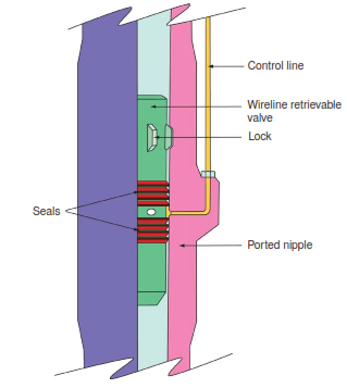
- Wireline retrievable safety valves. (run and install them in a wireline nipple in the completion string after landing completion and installing the Christmas tree).
- Tubing retrievable safety valves (installed as an integral part of the completion string).
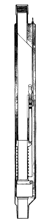
- Combination safety valves. We can find trolled subsurface safety valve on the market today that offers approximately the same advantages as the tubing and wireline retrievable valve (Fig. 3). A sleeve, a flapper, and a return spring are installed and integrated into the tubing. The jack is off-center and set in the equivalent of a side pocket mandrel. As a result, it is readily retrievable for maintenance by the same technique we use for gas-lift valves.
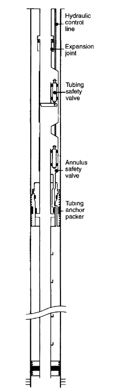
- Subsurface tubing-annulus safety valves. We use this system in gas-lifted production wells, mainly offshore. Generally, it consists of two valves, one for the tubing and the other for the annulus. We can both open the tubing and the annulus. It also requires setting a second packer in the upper part of the well at the same depth as the safety valve (Fig. 4). A sliding sleeve allows gas to flow or prevents it from flowing into the annulus by opening or closing the bypass of the upper packer. A hydraulic jack fixed on the tubing will move and control the sleeve as the tubing safety system.
- Other safety valves. Subsurface safety valves electromagnetically controlled from the surface, now at the research and development stage, do not require installing any hydraulic control line. If this type of valve proved its reliability, completion would be more straightforward. In addition, we could set the valve deeper down in the well.
Surface Control Subsurface Safety Valve Designs
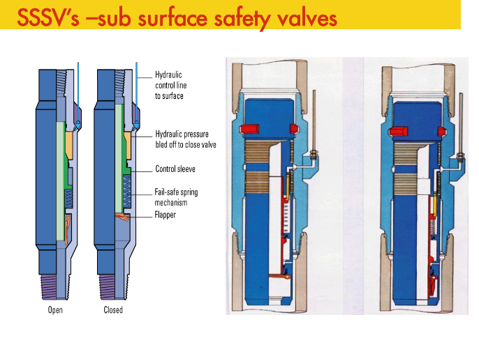
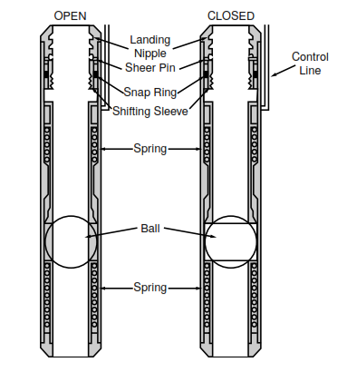
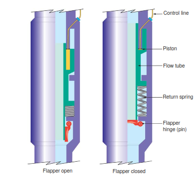
Figures 5 and 6 are typical examples of a fail-safe close ball type WRSV and a flapper type TRSV. In these examples, the essential features are the valve mechanism and the hydraulic operation.
WRSVs and TRSVs are available with optional ball or flapper-type closures. However, the flapper type is becoming increasingly popular due to its reliability, brought about by a more straightforward design and operation.
Usually, TRSVs are full-bore valves, i.e., the inside diameter is compatible with the production tubing. TRSVs that pass through tubing to reach the SVLN (landing nipple), have comparable bore sizes that are much less than the tubing.
Ball Valve Mechanism
Figure 7 shows an exploded view of a ball and seat assembly. This assembly consists of the ball, seat, control arms, sleeve weldment, and alignment pins; the ball has slots to accommodate the drive pins. The ball and seat assembly provides a metal-to-metal sealing system and is the primary seal to well pressure below the safety valve when closed.
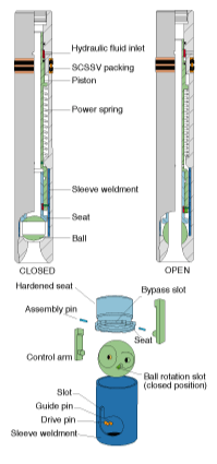
Downward movement of the surface control subsurface safety valve seat and control arms within the sleeve weldment will move the ball downwards. When the sleeve weldment butts up against the lower assembly, a 90° rotation of the ball will have occurred, moving it to the open position. The rotation is due to the slots in the ball acting on the drive pins. When removing hydraulic pressure, the spring pulls back the ball, assisted by any well pressure, reversing the opening action. The additional force from well pressure will assist in making a pressure-tight seal.
Flapper Valve Mechanism
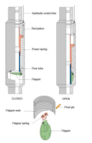
Figure 8 shows an exploded view of a flapper and seat assembly. The flow tube moves downwards during actuation and mechanically opens the flapper system. The reverse of the above action closes the flapper valve. The Flapper spring will initially assist with the closure and then the well pressure. This flapper closure system has a metal-to-metal ‘hard’ seat for high-pressure sealing and a ‘soft’ seat for low-pressure sealing.
Surface Control Subsurface Safety Valves Setting Depths
The setting depth of the SCSSV depend on the following factors:
- SCSSV Characteristics
- Well Environment
- Production
| SCSSV Characteristics | Setting Depth Considerations |
| Valve closing pressure | Maximum fail-safe setting depth. |
Note: The valve closing pressure depends on the control line fluid gradient, operating valve friction, and the manufacturer’s recommended operating safety margin.
| Well environment | Setting depth considerations |
| Land well | Recommended minimum SCSSV setting depth 100 ft. below ground level. |
| Offshore well | The recommended minimum SCSSV setting depth is 50 ft. below deepest pile penetration on a fixed steel platform. |
| Simultaneous drilling and production. | Below deviation kick-off depth |
| High blowout potential | Below is the estimated cratering depth |
| Well Production | Setting Depth Considerations |
| Wax deposition | Wax deposition depth (oil wells). |
| Hydrate formation | Hydrate formation depth (gas wells). |
Note: The well temperature will influence above factors during production.
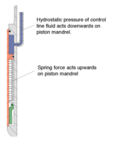
When the surface control manifold removes the control line pressure, the force of the power spring in the Surface Control Subsurface Safety Valves must be able to overcome the hydrostatic head of the control line fluid and seal friction during the closing cycle. Figure 9 illustrates these forces. The closing force and, hence, the closing pressure will determine the maximum setting depth of a TRSV or a WRSV in the tubing. The maximum fail-safe depth for a particular safety valve model is not standard. We must determine the maximum fail-safe depth for each particular SCSSV installation.
SCSSV Hydraulic Actuation
As discussed above, both ball and flapper valve mechanisms require the downward movement of an internal actuator to open the valve. The achievement of this motion is by applying hydraulic pressure from the surface. Then this pressure goes down through the control line to the valve, and acts on a piston (or pistons). This action will force the piston downwards against the opposing force of an internal power spring and well pressure. This spring provides the stored potential energy to close the valve when hydraulic pressure is removed or lost.
Figure 10 shows the two methods of achieving this actuation.
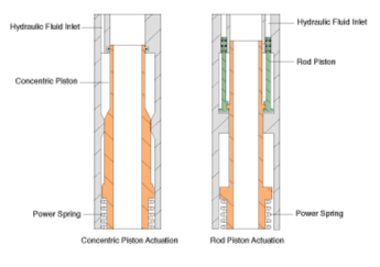
Concentric Piston Actuation
The pumping of hydraulic fluid into an annular space within the valve will move a concentric piston downwards against the force of the power spring.
Rod Piston Actuation
When we pump hydraulic fluid into small bores, it forces rod pistons downwards against the force of opposing power springs. Rod piston actuation reduces the hydraulic chamber volume and permits the operation of valves at greater depths. However, the penalty is higher operating pressures and the corresponding impacts on the system reliability and costs.
Surface Control Subsurface Safety Valve Equalization
After closing SCSSV in a producing well, the well will build up pressure below the valve to static conditions. This pressure may be many times higher than the flowing pressure at the valve at the time of closure. Reopening the valve with a differential pressure across the closure mechanism will require higher than normal control line pressures. This, in turn, will subject the valve’s internal components to higher stresses, especially the primary sealing surfaces. In most circumstances, the pressure required will exceed the rating of the wellhead, the tubing hanger, or the SCSSSV hydraulic control line. We must reduce or eliminate the pressure differential across the valve. This action will prevent damage to a safety valve system due to such stresses. When we reach such a condition, we can reapply hydraulic pressure to the SCSSSV control line to open the valve.
Equalization Methods
We generally can use the following methods to equalize fluid pressures above and below a closed SCSSV:
- Re-pressurizing the production tubing above the SCSSSV from another well (if sufficient well pressure exists) via the production manifold.
- Pumping a fluid that is compatible with the production fluid (e.g., diesel for thin oils) into the production tubing and pressuring this fluid until achieving equalization across the valve.
- Pumping a supply of inert gas (e.g., nitrogen) at sufficient pressure into the production tubing until
equalization occurs. - In addition, using a combination of the methods described in 1 and 3. We can reach this deficiency with an additional inert gas supply if other wells cannot supply sufficient pressure.
- Furthermore, using the available built-in equalization feature of the SCSSSV installed; may be used in conjunction with some of the methods described above.
- Equalization via the annulus through the (gas lift) blowdown loop.
Generally, whichever method of SCSSSV equalization is chosen will depend upon the source of pressure and, possibly, Company policy.
Non-Equalizing SCSSSV
As the name implies, non-equalizing SCSSSVs have no internal mechanism to assist in equalizing pressure across the safety valve. Therefore, the only method available is re-pressurizing the production tubing above the safety valve via the Christmas tree. Then, after equalization, the appropriate control line pressure, as recommended by the SCSSSV manufacturer, is applied to the valve; the magnitude of this pressure depends on the valve opening pressure, the setting depth of the valve, the control line fluid gradient, and a safety factor margin. The advantage over an equalizing SCSSSV is that it is more reliable due to its more straightforward design. The disadvantages are that an external pressure source is required for equalization, and improper operation against differential pressure can damage the valve.
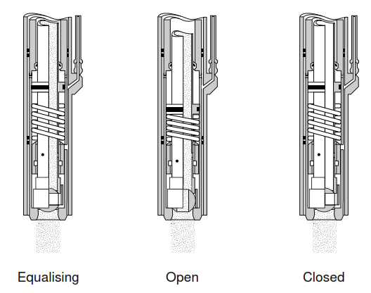
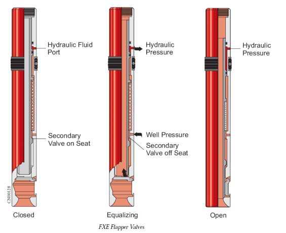
Equalizing SCSSSV
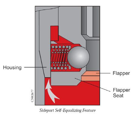
Equalising SCSSSVs provide an internal mechanism whereby pressurized well fluid below a closed valve can be introduced into the production tubing above the valve to facilitate equalization of pressure. In general, pressurized well fluid below a safety valve can bypass the closed valve by moving a secondary valve offseat. This slight movement of the secondary valve is provided by applying an appropriate control line pressure which only opens the secondary valve system; the magnitude of this pressure depends on the valve opening pressure, the setting depth of the valve, and the control line fluid gradient. The only advantage of this valve vis-a-vis the non-equalization valve is that it requires no outside pressure source. However, it is much less reliable as there are more seals and sealing surfaces.
SCSSSV Control Manifolds
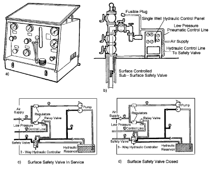
Since SCSSSVs are fail-safe close valves, they must be held open by an external pressure source. Surface control manifolds are designed to provide and control the hydraulic pressure required to hold an SCSSSV open. Figure 14 illustrates a typical portable SCSSV surface control manifold; wireline operators might use such a manifold to keep a TRSV open (after isolation from the primary ESD system) during routine wireline work on a well. The main components of such a manifold are the air supply and regulation system, the low-pressure system for pneumatic control (3-way controller, fusible plug, hi-lo pressure pilot, manual shutdown), and the hydraulic system for valve actuation (control line).
Surface Control Subsurface Safety Valve Failure Options
To ensure that safety valves will work if required, they should be periodically tested. The testing frequency (i.e., inflow testing) is dictated by the failure rate but is typically between three months and a year. The maximum permissible leak rate is dictated by company or government policy. ISO 10432 (2004b) and the preceding API guidelines have a relatively lax allowable 15 SCF/Min leak rate for gas and 400 CC/Min (25 in. /min) for liquids.
If the safety valve mechanism of a wireline retrievable valve fails, it can simply be replaced. If the mechanism of a tubing retrievable valve fails, there may be an opportunity to insert a wireline retrievable valve in a nipple profile above the flow tube of the tubing retrievable valve. Most tubing retrievable valves incorporate a permanent method of locking open the valve (e.g., by punching the flow tube). Communication between the tubing and the original control line can then be established by punching a hole in a pre-designated spot (depth control achieved by using a nipple no-go) or by shifting a pinned sleeve via a dedicated nipple profile. Dual seal bores and a nipple profile then allow the insertion of a wireline retrievable valve.
Control Line Failure
For any surface-controlled safety valve, if the control line or control line connection fails (control line to annulus communication), then there is little alternative but to replace the upper completion and make a control line repair. Sometimes, a storm choke can be run as a temporary solution. Storm chokes are so-called as they were run into wells without safety valves in the Gulf of Mexico and were there to protect the platform from catastrophic, hurricane-induced well failure.
These valves close (by the force of a spring or nitrogen charge) at a preset pressure or pressure drop through the valve. They are preset such that they stay open during production rates but close if fully open flow is encountered (e.g., atmospheric surface pressure). Storm chokes are notoriously unreliable (inadvertent closure or failure to close when required) and should only be used as an interim measure and ideally retrieved and recalibrated monthly. They are unlikely to close if there is a significant but restricted leak at the surface.
References:
- AES 1300 Drilling and Production – Delft University of Technology
- ENI completion Design Manual
- Well Completion & Servicing – Translated from the French by Barbara Brown Balvet and reviewed by Philippe Beun
- Well Completion Design Book