A landing nipple is a completion-tubing component with a machined locking profile and sealbore for a compatible lock mandrel and downhole device. Selective systems allow a chosen landing location; no-go systems use a locating shoulder. The nipple provides the receptacle, but the installed plug, valve or instrument assembly determines the function.
This guide explains landing-nipple types, legacy equipment names, compatibility checks and retrieval planning. The key engineering distinction is reaching a nipple, locking in it and sealing in it are separate requirements. It is a design reference, not a running or pulling procedure. [1][4]
Landing Nipple, Lock Mandrel and Plug: What Is the Difference?
| Component | Main function | What it does not establish |
|---|---|---|
| Landing nipple | Provides the machined landing/locking geometry and sealing bore in the tubing. | An empty nipple does not shut off flow. |
| Lock mandrel | Anchors a compatible device by engaging keys or dogs with the receiving profile. | Mechanical engagement alone does not prove a pressure seal. |
| Packing stack or seal assembly | Seals between the installed assembly and the nipple sealbore. | Packing cannot compensate for an incorrect profile or damaged bore. |
| Plug, valve, choke or instrument | Provides isolation, directional flow control, throttling or measurement. | Not every device isolates pressure in both directions. |
| Running and pulling tools | Install or recover the appropriate lock/device assembly. | Matching nominal size alone does not establish tool compatibility. |
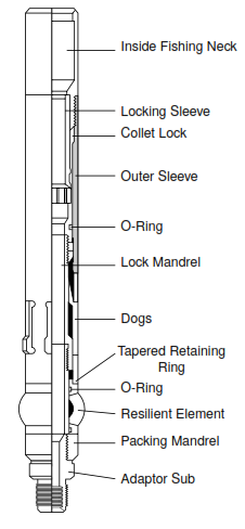
Common lock components include a fishing neck, an expander, keys or dogs, a retaining arrangement and a packing mandrel. A locking mechanism holds the keys engaged after the running tool releases. The component layout and release method depend on the model. The completion-training reference describes these functions in Section 3.5.1. [1]
Landing Nipple Applications in Well Completion
The installed accessory gives a landing nipple its operational role. Typical uses include the following, provided the complete assembly is qualified for the intended conditions:
- Landing a blanking plug for tubing isolation, testing or an approved hydraulic packer-setting arrangement.
- Locating a compatible wireline-retrievable subsurface safety valve in its designated nipple system.
- Supporting a downhole choke or a pressure/temperature gauge hanger.
- Locating a straddle or other compatible flow-control assembly within the well completion.
A standard non-ported nipple does not create tubing-to-annulus communication. That requires an appropriate ported component or arrangement, such as a sliding sleeve. Similarly, a nipple-mounted blanking plug closes a tubing flow path; a production packer seals an annular path. The barrier plan must address the relevant paths independently. [1][4]
Selective vs. No-Go Landing Nipples
The main difference is how the assembly is located. A selective system uses a matching profile or a running-tool selection mechanism to choose the target nipple. A no-go system stops the matching assembly at a dimensional shoulder. Ported and safety-valve nipples describe application features as well as locating geometry; these labels are not a universal interchangeability system.
| System | How the target is selected | Planning implication |
|---|---|---|
| Profile-selective | Coded nipple geometry matches the appropriate locator/lock. | Record each profile and its installed depth; position count is system-specific. |
| Running-tool-selective | The running arrangement selects among compatible same-profile nipples. | Review selection method, seal passage through upper bores and lower-tool access. |
| Top or bottom no-go | A shoulder stops the matching locating feature. | Check shoulder location, no-go ID and all restrictions above the destination. |
| Ported / safety-valve arrangement | Application-specific ports, seals and control interfaces supplement the landing/locking system. | Verify the whole valve or flow-control arrangement, not only the nipple designation. |
Selective Landing Nipple System
Selective nipples are useful where a completion needs several potential installation depths without progressively reducing every nipple bore. Selection is either built into the profile/locator combination or controlled by the running system. Neither approach removes the need for a restriction survey and a documented nipple tally. [1]
Selective Internal Profile
In a profile-selective arrangement, the locator must match the intended nipple geometry. The completion drawing should identify the coded position, sealbore and measured depth of each nipple. Do not substitute a lock merely because it is described as the same tubing size.
For example, the historical ENI wireline manual describes an Otis S/T system with seven coded positions and a specified installation order. That number belongs to the documented system; it is not the capacity of every selective completion. [3]
Setting-Tool-Selective Landing Nipples
Running-tool selectivity permits a compatible lock and flow-control assembly to be placed in a selected nipple among several with the same profile. After installation, the running tool is recovered while the lock, seals and accessory remain. Halliburton documents this principle for its X/R family. [5]
Same-profile flexibility does not mean unrestricted practical access. Verify tool travel through each upper component, the condition of successive sealbores, and the packing arrangement. The training handout warns that repeated passage through upper bores can damage seals; current supplier offerings show why that concern should be evaluated for the actual installation rather than treated as a universal ban on selective systems. [1][5]
Prespaced Magnet Selectivity: Legacy Equipment
Legacy descriptions also refer to matching magnet spacing between a running assembly and a nipple. The references verified for this guide do not establish a current transferable specification for that arrangement. For an existing magnet-coded installation, obtain its original drawings and operating manual; do not infer the number of available locations or an activation sequence from a generic description.
Nonselective Landing Nipple: Top and Bottom No-Go
A no-go landing nipple has a locating restriction that prevents the designated landing feature from passing. The shoulder may be above or below the sealing section, depending on the equipment family. This locates the assembly; the approved locking and sealing actions must still be completed. The receiving profile and lock must still be a compatible pair.
A lower tool must clear every upstream restriction in its running configuration. Several no-go locations may therefore require a planned size sequence, while a bottom no-go can also terminate a series of compatible selective nipples. Halliburton describes the latter application for XN/RN nipples. [6]
Do not confuse tubing OD, nipple sealbore, no-go ID and maximum running-tool OD. A sealbore dimension identifies where seals operate; it does not by itself identify the smallest passage through the completion. ENI’s completion-design manual treats sealbore, no-go diameter and lock OD as separate selection inputs. [2]
Available Nipple/Mandrel Systems: Names Are Not Compatibility
The examples below explain the legacy nomenclature retained in many completion records. Use the manufacturer, family, size, part number and drawing revision to identify an installed system. A letter such as R is not a cross-manufacturer compatibility code. Historical diagrams are useful for recognition, not as current dimensional or pressure-rating certificates.
Common Baker Landing Nipple Systems
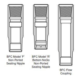
In the Baker examples described in ENI’s wireline manual, Model F is associated with top-no-go seating, while Model R uses a bottom-no-go arrangement. The manual pairs FWG/W2 and RZG/Z2 equipment with these respective systems. Those are documented examples, not permission to combine similar-looking parts from other suppliers. [3]
Depending on the matched lock and accessory, a nipple can support plugging, flow regulation or instruments. The function and differential-pressure capability belong to the assembled device. Check the selected product documentation rather than copying a pressure limit from an unrelated model.
Common Halliburton Landing Nipple Systems
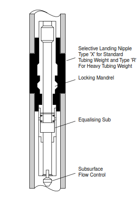
Halliburton’s Otis X/R products use running-tool selectivity. Its published descriptions associate X with standard-weight tubing and R with heavyweight tubing. XN and RN are bottom-no-go counterparts used singly or at the bottom of a compatible series. These product descriptions do not make Baker Model R and Otis R interchangeable. [5][6]
Retractable keys permit the appropriate running configuration to pass compatible profiles. Once installed, the specified lock and packing provide retention and sealing. Obtain the current size-specific ratings, seal materials and permitted pressure directions; a general “10,000 psi” family description cannot replace that check.
Other Halliburton Types and Legacy Lock Arrangements
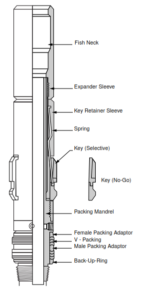
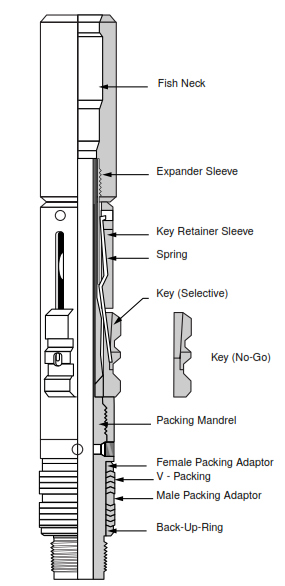
S-series profile-selective equipment uses coded locating geometry rather than the same selection principle as the X/R running-tool system. ENI’s S/T example is described in Section 10.3. Other legacy designations, including N no-go references, need their own model documentation before assigning a profile, bore limit or matching mandrel. [3]
When reviewing an old schematic, record the nipple manufacturer and model in one column and the lock, seals, accessory and intervention tools in separate columns. This prevents an apparently complete equipment list from hiding a mismatched equalizing prong or fishing-neck connection.
Landing-Nipple Clearance: A Worked Access Check
Illustrative dimensions only—not manufacturer limits. Assume a proposed assembly has a maximum rigid running OD of 2.280 in. The target nipple has a suitable 2.313-in. sealbore, but an upstream no-go restriction has a 2.250-in. clear bore.
Upstream diametral clearance = 2.250 − 2.280 = −0.030 in. The rigid assembly cannot pass that restriction, even though its destination sealbore appears large enough. Check the entire access route before focusing on the target profile.
A different, hypothetically compatible assembly with a 2.200-in. rigid OD would leave 0.050 in. diametral clearance, or 0.025 in. per side when concentric. That arithmetic is only a preliminary fit check, not an acceptable running-clearance recommendation. Tolerances, deposits, deformation, tool length, well deviation and the manufacturer’s packing/pass-through requirements remain to be assessed.
The clearance-screening approach is an original illustration of the dimensional dependencies discussed in ENI Section 8.4. The manual’s historical company clearance rules are not adopted here as universal acceptance criteria. [2]
Pressure Equalization Before Retrieving a Plug
A plug can carry substantial pressure load even when its lock has been correctly installed. Pressure below it tends to drive the assembly upward; pressure above it loads the assembly downward. Surface readings alone may not establish the differential at the plug, particularly with different fluid columns or trapped pressure. Use the appropriate hydrostatic-pressure calculation and the approved well-barrier assessment.
Illustrative force check: for a simple blanked circular area with an assumed effective diameter of 2.50 in. and 3,000 psi net differential, F = ΔP × πd²/4 ≈ 14,726 lbf. The same differential reversed changes the direction of the ideal pressure thrust. These are assumed values, not a tool pressure rating, wireline pull limit or retrieval instruction.
Real assemblies may have different effective pressure areas, bypasses and pressure-balanced sections. Establish those areas from the actual drawing. The example explains why a retrieval plan must address differential pressure before releasing the retaining mechanism; it does not calculate the permitted jarring or pulling load.
ENI’s documented Baker W/Z procedures require equalization to be confirmed before the remaining plug body is retrieved. Other systems use different access tools and equalizing arrangements. Follow the selected equipment’s sequence and the well program, including a contingency if the equalizing path is blocked. [3]
Setting Mandrels Not Requiring a Nipple Profile
A damaged or unavailable nipple may lead the engineer to consider a qualified tubing plug, collar lock or other alternative anchoring system. These do not automatically share the same holding principle, pressure direction or retrieval method as a profile-locking mandrel. Compare the assembly with the actual tubing bore, connection geometry and required plugging and recovery strategy.
The Type D example in ENI Section 10.2 engages suitable tubing-collar recesses; the documented tool cannot be assumed to fit a connection without that recess. A blanket 1,500-psi limit or prohibition on pressure from above is not a general rule for all nippleless equipment. Qualification must be established for the selected product. [3]
A slip-anchored device in a controlled-ID section is another architecture described in the completion handout. It should be treated as an engineered alternative, not as an improvised substitute for a missing nipple. A contingency may also require dedicated wireline fishing equipment and a recovery plan. [1]
Ancillary Equipment for Nipples: Flow Couplings
Restrictions and changes in flow area can create local turbulence and erosion, particularly where produced solids are present. A flow coupling is a thick-walled completion component that provides additional erosion allowance. Its role is not simply to straighten the flow or guarantee elimination of turbulence. The SLB glossary describes installation near components such as landing nipples. [7]
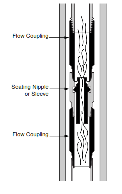
The completion-training handout distinguishes internal erosion protection from the external protection supplied by a blast joint. Select the coupling bore, material, length and position using expected fluids, solids and service life. Do not transfer a historical coupling-length rule to every completion without checking the design basis. [1]
Landing Nipple Selection and Intervention Checklist
Prepare a nipple-and-accessory register before completion or intervention. Alongside measured depths, retain the relevant drawing numbers and revisions. A useful review covers the following six questions:
| Check | Required evidence | Reason to stop and resolve |
|---|---|---|
| Identity and fit | Manufacturer, nipple/profile part number, lock size, seal stack and accessory connection. | A name or tubing OD is being used in place of a verified match. |
| Access route | Minimum upstream bores, no-go shoulders, tubing drift and the entire running assembly envelope. | The tool fits its destination but cannot reach it. |
| Pressure and service | Both pressure directions, temperature, fluid compatibility and complete assembly ratings. | Only the nipple rating has been checked, not the lock, seals and accessory. |
| Installation verification | Applicable selection method, depth correlation, locking confirmation and pressure-test criteria. | Landing or running-tool release is being mistaken for proof of isolation. |
| Recovery | Fishing neck, pulling tool, equalizing method, barriers and debris contingency. | Pressure cannot be assessed/equalized or the release mechanism is inaccessible. |
| Life-cycle use | Future lower-zone access, sealbore crossings, erosion exposure and planned workovers. | The initial arrangement prevents a later required operation. |
A sealed nipple-mounted device and its host tubing form only the paths covered by that arrangement. A wellhead back-pressure valve is a different installation, and neither name alone establishes a complete well barrier. Keep the device purpose, pressure direction and verification requirement explicit in the approved program.
Landing Nipple Questions
Does a no-go shoulder prove that the plug is locked and sealed?
No. It provides a locating stop for the matching feature. Lock engagement, seal condition, accessory function and required verification are separate checks. Landing at the expected depth is not by itself evidence of pressure isolation.
Are Baker R and Otis R landing nipples interchangeable?
Not on the basis of the letter R. The referenced Baker example is bottom-no-go, whereas the Otis R family is running-tool-selective. Compatibility requires the exact manufacturer, profile, dimensions, lock, seals and supporting documentation.
Is nipple size the same as production-tubing size?
No. Tubing OD describes the host tubular, while the nipple sealbore and no-go restriction describe different internal features. Compare those dimensions with the maximum running envelope of every component that must pass through them.
Technical References and Scope
- Transocean, Completion Equipment training handout. Sections 3.4–3.5.2, printed pages 18–21. Used for nipple/lock components, applications, selectivity, seal-passage risks, controlled-ID alternatives and flow-coupling functions. Edition/date is not established in the supplied copy.
- ENI/Agip, Completion Design Manual, STAP-P-1-M-7100, Rev. 0. Section 8.4, pages 237–239. Used for the interaction of nipple sealbore, no-go ID, lock OD and upstream restrictions. Historical company dimensions and pressure bands are not prescribed as universal limits.
- ENI/Agip, General Wireline Procedures Manual, STAP-P-1-M-7110, Rev. 0. Sections 10.2–10.5 and 10.7. Used for legacy collar-lock/profile examples and pressure-equalization considerations. Model-specific running, jarring and retrieval instructions are not reproduced as general procedures.
- SLB Energy Glossary: landing nipple. Terminology and application classes.
- Halliburton: X and R landing nipples and lock mandrels. Current product description reviewed October 11, 2026; running-tool selectivity and family context.
- Halliburton: XN and RN landing nipples and lock mandrels. Bottom-no-go configuration and application context, reviewed October 11, 2026.
- SLB Energy Glossary: flow coupling. Thick-wall erosion-protection function.
Scope: The comparison tables, review checklist and assumed-number examples are educational synthesis, not manufacturer certifications. Use the current documentation for the installed equipment and the approved well program for selection, pressure testing, installation and recovery. Legacy mechanisms without verified product data are identified as such.