This article aims to understand how to perform various directional drilling survey calculation methods and terminology. We will provide a simple Excel spreadsheet to help in your calculations as an average angle, radius of curvature & minimum curvature Directional surveying spreadsheet.
Nowadays, you will find a lot of software for directional drilling survey calculation methods. Simultaneously, I have found an excellent directional survey calculations Excel spreadsheet, which will help you in your calculations.
Regardless of which conventional directional survey method is used (single-shot, multishot, steering tool, surface readout gyro tool, MWD), the following three pieces of information are known at the end of a successful directional survey:
- Survey Measured Depth
- Borehole Inclination
- Borehole Azimuth (corrected to relevant North).
To be sure of the latest bottom-hole position, it is necessary to perform the directional survey calculation, which includes the three inputs listed above. Only then, plot the latest bottom-hole coordinates on the directional well plot (TVD vs. Vertical Section on the vertical plot, N/S vs. E/W rectangular coordinates on the horizontal plot). Then, you can make projections for the target, etc.
The Purpose Directional Drilling Survey Calculations
- Orient deflection tools for navigating well paths.
- Determine the exact bottom hole location to monitor reservoir performance.
- Monitor the actual well path to ensure reaching the target.
- Fulfill requirements of regulatory agencies, such as the US Minerals Management Service (MMS).
- Calculate the TVD of the various formations to allow geological mapping.
- Ensure that the well does not intersect nearby wells.
- Evaluate the Dog Leg Severity (DLS), the total angular inclination, and Azimuth in the wellbore, calculated over a standard length (100 ft or 30 m).
Principles of Surveying
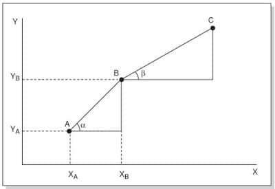
The basic principles of directional drilling surveying calculations can be illustrated by considering the two-dimensional system below. The position (coordinates) of point B relative to the reference point A can be determined if the angle α and the distance AB are known. If the position of point A is defined as 0,0 in the X, Y coordinate system, the position of point B can be determined by the following equations:
YB = AB Sin α
XB = AB Cos α
Hence, the displacement of point B in the X and Y directions can be determined if the angle α and the linear distance between A and B are known. The same procedure can evaluate the position of a further point C. The X and Y displacement of C relative to the reference point A can be determined by adding the X and Y displacement of Point B to A and those of Point C to B.
This process of defining the position of a point relative to a specific reference point can be continued for any number of points.
Wellbore Surveying
This same principle is applied to wellbore surveying. In the case of directional drilling surveying by any method, however, the calculations procedure must include consideration of the following:
- The process must be applied in three dimensions.
- The trajectory between the survey points (the path of the wellbore) is not generally a straight line.
The three-dimensional aspect of the problem is not a significant issue since the same process as that outlined above can be applied to the vertical and horizontal displacement of the survey points (stations). The procedure is described below.
The fact that a straight line does not generally define the trajectory of the wellbore is accommodated by assuming that the trajectory of the wellbore follows a simplified geometrical model.
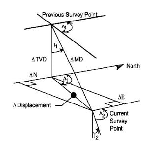
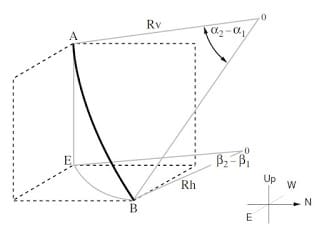
Now, Let’s check the below figure & definitions to fully understand all directional drilling survey calculation methods and terminology.

- “O” is the Reference Point for the Well.
- “S” is the Surface Location Reference Point.
- “B” is a Survey Point.
- “a” is the Azimuth in degrees of the Vertical Section plane. It is measured in a Horizontal Plane from the North Direction (geographic), beginning at 0° and continuing through 360° (clockwise from the North axis).
- “TVD” is the projection of SB (Measured Depth, MD, along the well path) onto the vertical axis “z”. The distance is SB3.
- “HD” is the Horizontal Displacement, measured in the Horizontal plane passing through the Survey Point. The distance is BB3 (between Survey point end “z” axis).
- “VS” is the Vertical Section, the length of the Horizontal Displacement (HD) projection onto the Vertical Section plane defined by its Azimuth. The distance is B3B2.
- “A Vertical Section Plane” is defined by its Azimuth and the US origin point. Usually, the Vertical Section passing through the center of the Target is used for plotting the well profile.
How To Determine The Coordinates Of Directional Survey Stations
The only information that is required to perform Directional Drilling Survey Calculations by any of its methods & to determine the coordinates of all points in the well trajectory is, therefore:
First, The position of the initial reference point
(generally the Rotary Table)
Second, The measured depth (AHD)
The depth of the survey station is provided by the driller. It is calculated based on the length of the drill string in the wellbore and the distance between the drill bit and the survey tool.
Third, The direction (Degrees from North)
The direction in which the drill bit points when a survey is taken is expressed in degrees Azimuth.
Azimuth is the angle in degrees (°) between the horizontal component of the wellbore direction at a particular point, measured in a clockwise direction from the reference (generally North). Azimuth is usually expressed as a reading on a 0 – 360° (measured from the North) scale. For directional surveying, there are three azimuth reference systems :
- Magnetic North;
- True (Geographic) North;
- Grid North.
Azimuth Reference Systems
Magnetic North (MN)
This is the direction of the horizontal component of the Earth’s magnetic field lines at a particular point on the Earth’s surface. A magnetic compass will align itself to these lines with the positive pole of the compass indicating North.
True (Geographic) North (TN)
This is the direction of the geographic North Pole. This lies on the axis of rotation of the Earth. The direction is shown on maps by the meridians of longitude.
Grid North (GN)
The meridians of longitude converge towards the North Pole and South Pole and, therefore, do not produce a rectangular grid system. The grid lines on a map form a rectangular grid system, the Northerly direction of which is determined by one specified meridian of longitude. The direction of this meridian is called Grid North.
For example, in the often-used Universal Transverse Mercator (UTM) coordinate system, the world is divided into 60 zones of 6 degrees of latitude, in which the central meridian defines Grid North. Grid North and True North are only identified for the central meridian. Comparison of coordinates is only valid if they are in the same grid system.
Conversions
All azimuths must be quoted in the same reference system to be meaningful. This is usually the Grid North system. Azimuths are often measured in systems other than the Grid North system.
Two conversions typically have to be applied to the measured azimuths:
- Grid Convergence
- Declination
Grid Convergence :
Grid convergence converts azimuth values between the Grid North and the specified True North system.
The grid convergence angle is the angle between the meridians of longitude (TN) and the North of the particular grid system (GN) at a given point. By definition, the grid convergence is positive when moving clockwise from True North to Grid North and negative when moving anti-clockwise from True North to Grid North.
The value of grid convergence depends upon location. Close to the Equator, the convergence is slight and increases with increasing latitude.
Declination:
The Declination converts azimuth values between the Magnetic North and True North systems. We can define declination as the angle between the horizontal component of the Earth’s magnetic field lines and the lines of longitude. By definition, the declination is positive when moving clockwise from True North to Magnetic North and negative when moving anti-clockwise from True North to Magnetic North.
Declination values change with time and location, and those representing the parameters during drilling should be used.
Fourth, The inclination (Degrees from the vertical) of the wellbore at the survey station
The inclination of the wellbore is the angle in degrees that the wellbore deviates from the vertical.
Directional Drilling Survey Calculations Methods / Models & Terminology
Several directional drilling survey calculation methods have been used in oilfields. You can download the directional drilling Excel spreadsheet at the end of the article.
Only four have had widespread use:
- Tangential calculation method.
- Average Angle calculation method.
- The radius of Curvature calculation method.
- Minimum Curvature calculation method.
The Tangential Calculation Method is the oldest, least sophisticated, and most inaccurate directional survey calculation method. This method should never be used.
Average Angle and Radius of Curvature Directional drilling survey calculation methods are used daily. The average Angle method (in particular) lends itself easily to a hand-held calculator. The radius of the Curvature method is more widely used. However, official directional survey reports should only use the above techniques when demanded by the customer.
The minimum Curvature survey calculation method should be used for all office calculations and official survey reports. Where possible, it should also be the field calculation method chosen. The directional driller is advised to have a hand-held calculator at the well site, which is programmed for both Radius of Curvature and Minimum Curvature methods of directional survey calculation Terminology.
Tangential
“Most Inaccurate Directional Drilling Survey Calculation Methods & Terminology”
This method uses the inclination and hole direction at the lower end of the course length to calculate a straight line representing the wellbore that passes through the lower end of the course length. Because the wellbore is assumed to be a straight line throughout the course length, it is the most inaccurate of the methods discussed and should be abandoned entirely.
∆North = ∆ MD sin I2 cos A2
∆East = ∆ MD sin I2 sin A2
∆TVD = ∆ MD cos I2
∆Displacement = ∆ MD sin I2
Balanced Tangential Calculations Method
Modifying the tangential directional drilling survey calculation method and terminology by taking the direction of the top station for the first half of the course length and then that of the lower station for the second half can substantially reduce the errors in that method. This modification is known as the balanced-tangential method.
This method is straightforward to program on hand-held calculators and gives accuracy comparable to the minimum curvature method. See the spreadsheet below.
∆North =1/2 x ∆MD (sin I1 cos A1 + sin I2 cos A2)
∆East = 1/2 x ∆MD (sin I1 sin A1 + sin I2 sin A2)
∆TVD = 1/2 x ∆MD (cos I1 + cos I2 )
∆ Displacement = 1/2 x ∆MD (sin I1 + sin I2 )
Average angle Directional Drilling Survey Calculation Method With Excel Spreadsheet
The directional survey calculation method uses the average of the inclination and hole-direction angles measured at the upper and lower ends of the course length. The average of the two sets of angles is assumed to be the course length’s inclination and direction. The well path is then calculated with simple trigonometric functions.
∆North = ∆ MD sin A cos B
∆East = ∆ MD sin A sin B
∆TVD = ∆ MD cos A
∆Displacement (CD) = ∆ MD sin A
∆Vertical Section = CD x cos ( B – target direction)
Where:
- A = (I1+I2)/2
- B = (A1+A2)/2
Download The Directional Drilling Survey Calculation Excel Spreadsheet For Average Angle Method & Terminology From Below.
Download Average Angle Method Calculations
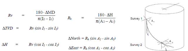
The Radius of Curvature Directional Drilling Survey Calculation Methods & Terminology
With the inclination and hole direction measured at the upper and lower ends of the course length, this directional survey calculation method generates a circular arc when viewed in both the vertical and horizontal planes. Curvature radius is one of the most accurate methods available.
In the below directional drilling survey calculations Excel spreadsheet, you will find that we are using this method to get these calculations.
Also, another directional drilling calculation Excel spreadsheet provided by Drillingformula is a good one to use quickly.
Download Radius Of Curvature Calculations
Minimum Curvature With Excel Spreadsheet:
Note: Most Accurate Directional Drilling Survey Calculations Methods and terminology
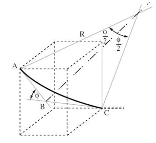
Before downloading the Minimum Curvature Method Spreadsheet, you should know that this method, the most accurate of all listed, uses the inclination and hole direction measured at the upper and lower ends of the course length to generate a smooth arc representing the well path.
The difference between the curvature-radius and minimum curvature directional drilling survey calculation methods and terminology is that curvature radius uses the inclination change for the course length to calculate displacement in the horizontal plane (the true vertical depth [TVD] is unaffected). In contrast, all minimum curvature method spreadsheets use the Dogleg Severity (DLS) to calculate displacements in both planes.
The minimum curvature method in the spreadsheet below is considered the most accurate. Still, it does not lend itself easily to standard hand-calculation procedures.

You Can Download This amazing Directional drilling survey calculation From the Drilling-Formula For Minimum Curvature Method Spreadsheet Below.
Download Minimum Curvature Calculation
Mercury Survey Calculation Method
It is so-called because it was used at Mercury, Nevada, at the U. S. nuclear test site. This directional survey calculation method combines the tangential and balanced tangential calculation methods. It considers the length of the survey tool (STL). It treats the portion of the course over the length of the survey tool as a straight line (tangential) and the rest of the course in a balanced tangential manner.
∆TVD = (∆MD-STL) /2 × (cos I1+cos I2)+STL × cos I2
∆North = (∆MD-STL) /2 × (sin I1+cos A1+sin I2 cos A2)+ STL × sin I2 cos A2
∆East = (∆MD-STL) /2 × (sin I1+sin A1+sin I2 sin A2)+ STL × sin I2 sin A2
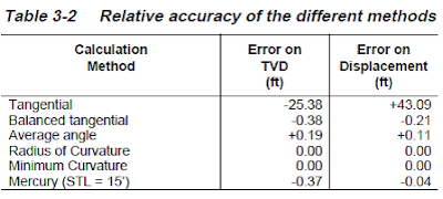
Comparison Between Different Directional Drilling Survey Calculation Methods & Terminology
The directional survey results are compared against those from the minimum-curvature method, as shown in the table below. Significant errors are seen in the tangential method for only approximately 1,900 ft of deviation.
This demonstrates that the tangential method is inaccurate and should be abandoned altogether. The balanced-tangential and average-angle methods are more practical for field calculations. They should be used when sophisticated computational equipment or expertise is unavailable. These should be noted as “Field Results Only.”
Dogleg severity
Dogleg Severity measures the amount of change of inclination and/or direction of a borehole. It is usually expressed in degrees per 100 feet or degrees per 10 or 30 meters of course length.
Several formulae are available to compute the total effects when there is a change in inclination and direction between survey points. In the following formulae:
Dogleg severity (DLS) = {cos-1 [(cos I1 x cos I2) + (sin I1 x sin I2) x cos (A2 – A1)]} x (100 ÷ MD)
- I1 = Inclination at Survey point 1.
- A1 =Azimuth at Survey point 1.
- I2 =Inclination at Survey point 2.
- A2 =Azimuth at Survey point 2.
The above formula is commonly used to estimate tubular goods’ fatigue and strength criteria. Therefore, it makes no assumptions about the well path and is independent of survey calculation methods.
Download Now Drilling Survey Calculations Excel Spreadsheet
This directional drilling calculation Excel spreadsheet version made by Drill-Bite has several new features:
- Compatibility with Excel 2007 to 2013 for Windows 32 and 64 bits (WinXP, Win7, Win8)
- Storing of multiple branches of the same well
- Anti-collision calculation (center to center only)
- Multiple wells drawing
- New file storing data (no backward compatibility provided)
dear sire
how can we get these document to download?
Just click on the image of the download