A conventional rotary drilling assembly is typically used when drilling a vertical well, or a deviated well’s vertical or tangent sections. When using an RSS Rotary Steerable Assembly or Non-Rotating Steerable Mud Motor Assembly in a deviated well, it is, of course, possible to drill the tangent sections of the well with the steering action. But In this article, we introduce how to use the Rotary Directional Drilling Bottom Hole Assembly BHA to Build ( Fulcrum Assembly), Drop (Pendulum BHA), or Hold (Packed BHA). Please Check Our Oil & Gas Directional Drilling Guide For More Information.
The BHA of the conventional assembly can also be designed in such a way as to result in an increase or decrease in the inclination of the wellbore. Still, predicting the rate at which the angle will increase or decrease is challenging.
The tendency of a Conventional Bottom Hole Assembly BHA Components & Design to result in an increase or decrease in hole angle is a function of the flexibility of the BHA & WOB (Check how to run WOB Calculations). Since all the Drill String Components are somewhat flexible, the BHA will bend when weight is applied to the bit(Check Full guide For Types of Drilling Bits). This will introduce a tilt angle at the bit. Predicting the impact of the above variables on the rate at which the angle will increase or decrease is complicated.
Three types of directional drilling BHA assemblies:
There are three basic types of assemblies used in directional drilling. They are:
- Building Assemblies,
- Dropping Assemblies, and
- Holding Assemblies.
A building assembly is intended to increase hole inclination, a dropping assembly to decrease hole inclination, and a holding assembly to maintain hole inclination. It should be noted that a building assembly may not always build angle. Formation tendencies may cause the assembly to drop or hold an angle. The building assembly is intended to build an angle. The same is true for the dropping and holding assemblies.
Fulcrum Assembly As A Building Directional Drilling Bottom Hole Assembly BHA
The principle behind a Fulcrum Assembly is to place a reamer near the bit and apply a high WOB. When WOB is applied, the Drill collars above the reamer will tend to bend against the low side of the hole, making the reamer act as a fulcrum forcing the bit upwards. The build-up rate depends on WOB, the collars’ size, the reamer’s position, and stabilization above the reamer.
This building fulcrum assembly uses a stabilizer (Check Drilling Stabilizer Design & Types) acting as a fulcrum in the directional drilling bottom hole assembly BHA to apply side forces to the bit. The magnitude of that force is a function of the distance from the bit to the tangency point. An increase in bit weight and/or decrease in drill collar stiffness will increase the side force at the bit, increasing the build rate.
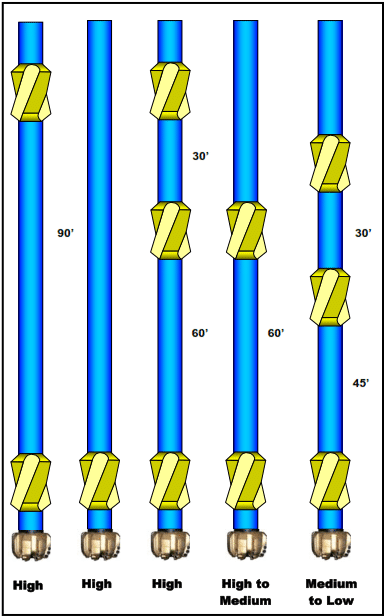
The most substantial building fulcrum assembly consists of one stabilizer placed 3 to 6 feet above the bit face with collars and drill pipe above the stabilizer (a second stabilizer can be placed 90 feet above the bit). This assembly will build under the majority of conditions. Of course, the rate of the build will be controlled by formation tendencies, bit and stabilizer types, lithology, bit weights (at lower inclinations), drill collar stiffness, drill string rpm’s, penetration rate, and hole geometry.
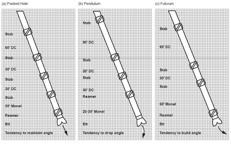
Another strong to moderate building fulcrum assembly consists of a bottom hole stabilizer placed 3 to 6 feet from the bit face, 60 feet of collars, stabilizer, collars, and any Drill Pipe Description & Specs. This is the most common assembly used to build an angle. The second stabilizer tends to dampen the building tendency. This assembly can be used when the previous assembly builds excessively. Other building assemblies can be seen in Figure 1.
The essential Directional Drilling Bottom Hole Assembly BHA For Building Actiony is:
Bit – sub-reamer – Monel DC – DC – stab – DC – stab – 90’DC – stab
To increase the build in any Directional BHA ( Fulcrum Assembly):
- Add more WOB
- Use smaller size monel (increase buckling effect)
- Reduce RPM and pump rates in soft formations
Packed Hole Assembly As a Holding BHA For Directional Drilling
This type of configuration is a very stiff assembly consisting of drill collars and stabilizers positioned to reduce bending and keep the bit on the course. This type of assembly is often used in the tangential section of a directional hole.
We can say that holding the inclination in a hole is much more complex than building or dropping an angle. Under ideal conditions, most assemblies either have a building or dropping tendency. Most straight-hole sections of a directional well will have alternating build and drop sections. When holding inclination, these build and drop sections should be minimized and spread out over a large interval to reduce dogleg severity.
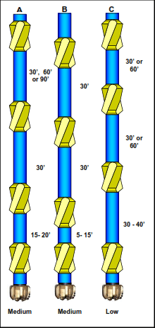
Amoco had statistically analyzed various holding assemblies, comparing their performance. Figure 2 shows three of the most common holding assemblies. Assembly “A” proved to be the most successful even though it maintained inclination only 60 percent of the time. Assembly “B” maintained an inclination of less than 50 percent of the time, and assembly “C” even less.
When selecting a holding assembly, research the well records in the area to determine which assembly works best for the types of drilled formations. If no information is available, use assembly “A” and adjust it as necessary.
The Mechanism Of Directional Holding BHA
The idea behind a holding assembly is to minimize the side force at the bit. By placing the stabilizers closer together, the amount of bending between the stabilizers is substantially reduced. There are also three stabilization points; one above the bit and two more points up the hole. Holding assemblies will be rigid with low bit side force, and the bit side force will be relatively unaffected by bit weight.
Rotary BHAs can also be made with an adjustable stabilizer. The adjustable stabilizer is where the gage can be adjusted while the stabilizer is downhole. They are usually adjusted by cycling pump pressure and weight (mechanical and hydraulic). The adjustable gauge stabilizer is usually placed in a rotary assembly, as shown in Figure 7-18. The assembly can hold, build or drop inclination with the adjustable gage stabilizer on top. With the assembly on the left side of Figure 7-18, the assembly will have a build tendency if the top stabilizer is significantly under gage, will have a dropping tendency if the top stabilizer is full guage, and will have a hold tendency if the top stabilizer is moderately under gage. With the assembly on the right, the middle stabilizer is the adjustable gauge stabilizer. If the stabilizer is under gauge, it will be a building assembly. The stabilizer will be a holding assembly if it is a full gauge.
The adjustable gauge stabilizer makes the rotary assembly partially steerable. The gauge on the stabilizer will have a predictable effect on inclination but not a predictable effect on the direction. However, it is beneficial in wells where the hole drag will minimize the effectiveness of the steerable motor assembly. It is also considerably less expensive than the rotary steerable assembly.
In practice, finding a tangent assembly that maintains a tangent angle and direction is challenging. Short drill collars are sometimes used, and reamers or stabilizers run in tandem.
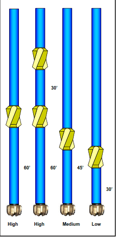
Pendulum Assembly or Dropping BHA
The principle behind a Pendulum Assembly is that the unsupported weight of drill collars will force the bit against the low side of the hole. The resulting decrease or drop off in angle depends on WOB, RPM, stabilization, and the distance between the bit and the first reamer.
A dropping assembly is sometimes referred to as a pendulum assembly. A stabilizer is placed at 30, 45, or 60 feet from the bit in this assembly. The stabilizer produces a plumb-bob or pendulum effect, hence the pendulum assembly. The purpose of the stabilizer is to prevent the collar from touching the wall of the hole, causing a tangency point between the bit and the stabilizer.
An increase in the effective length of the pendulum bottom hole assembly (the length below the tangency point) increases the weight. Since the force, that weight determines FP, the force FP also exceeds the force FB due to bending. The net result is a side force on the bit, causing the hole to drop angle.
Additions of bit weight will slightly decrease the dropping tendency of this assembly because it increases the force due to bending FB. Should enough bit weight be applied to the assembly to cause the collars to contact the borehole wall (between the stabilizer and the bit), the assembly will act similarly to a slick assembly. Only the assembly section below the tangency point affects the bit side force.
If the dropping tendency increases, larger diameter or denser collars should be used below the stabilizer. This increases the weight of the assembly, which increases by dropping tendency. For example, suppose a dropping assembly with 7-inch OD collars was used in a 12¼ inch hole. By substituting 9-inch OD collars for 7-inch OD collars, an increase in dropping tendency can be achieved. Figure 3 shows the calculated pendulum force for a 60-foot pendulum versus inclination with various size collars.
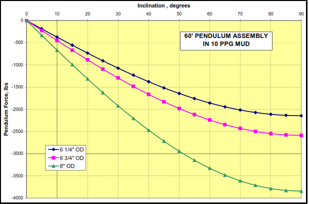
Dropping assemblies will have a higher rate of drop as hole inclination increases. The force FP (which causes the dropping tendency) is calculated using the following Equation 1:
Fp = 0.5 × W × Sin(I ) —- Equation 1
Where:
| FP | = | Side force at the bit caused by the weight of the unsupported section of the |
| W | = | bottom hole assembly, lbs. Buoyant weight of the unsupported section of the bottom hole assembly, lbs. |
| I | = | Hole inclination, degrees. |
An increase in hole angle will increase FP, resulting in an increase in dropping tendency. There is no pendulum force at zero degrees inclination. The sine of zero is zero, and the pendulum force will be zero. Pendulum assemblies are ineffective at low inclinations. Additional dropping assemblies can be seen in Figure 4.
The basic drop-off assembly is as follows:
Bit – Monel DC – reamer – DC – stab – DC – stab – 90′ DC – stab
To increase the tendency to drop angle :
- Apply less WOB (lower penetration rate)
- Apply more RPM and pump pressure in soft formations where jetting and Reaming down are possible.
- Use bigger size Monel DC below the reamer, and small DCs above.