For a hard shut-in lineup, the choke remains closed at all times other than during a well control operation. The choke line valves are aligned such that a flow path is open to the choking system with the exception of the choke itself and one choke line valve located near the blow-out preventer BOP stack. When the hard shut-in procedure is selected for closing in the well the blow-out preventer is closed.
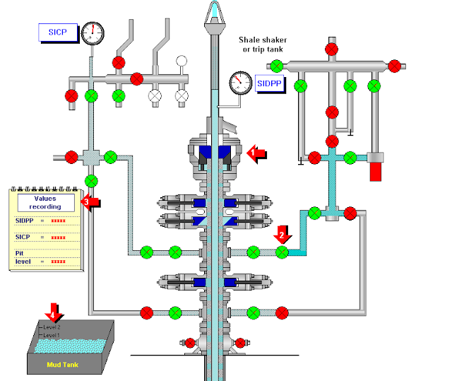
If the casing pressure can’t be measured at the wellhead, the choke line valve is opened with the choke or adjacent high-pressure valve remaining closed so that pressure can be measured at the choke manifold.
Hard Shut In Procedure In A Fixed Rig
- When any indication is observed while drilling that the well may be flowing, stop rotating the drill string and raise the drill string with pumps on until the tool joint is above the drill floor.
- Stop pumps and check for flow; if positive:
- Close annular BOP or pipe preventer rams.
- Open choke line HCR valve.
- Call the rig drilling supervisor and commence plotting a graph of shut-in drill pipe pressure. Check pit volume gain.
Hard Shut-In Procedure In A Floating Rig
- When any indication is observed while drilling that the well may be flowing, stop rotating the drill string, raise the drill string with pumps running, and space out for hang-off rams.
- Stop mud pumps and check for flow, if positive:
- With compensator at mid-stroke close annular or pipe rams.
- Open fail-safe valves on the choke line.
- Call supervisors and commence plotting a graph of shut-in drill pipe pressure. Check pit volume gain.
- If rams have been closed then reduce manifold pressure, slack off on drill string, and land tool joint on rams.
- Increase manifold pressure to 1500 psi – close wedge locks, adjust compensator to support drill string weight to BOP plus 20,000 lbs.
While Running/Pulling Casing
If a flow is detected while out of the hole, the following hard shut-in procedure must be used to shut in the well:
- Position the casing connection just above the rotary table and check for flow.
- If a positive flow is confirmed, or if there is any doubt, install a casing swedge and full open safety valve.
- Close the full-open safety valve.
- Close the annular preventer (with closing pressure reduced to the appropriate value) or check space out and close casing rams (as per predetermined procedure).
- Install the top drive, rig Kelly, or circulating head (as per the pre-determined procedure).
- Open the choke line HCR valve.
- Commence plotting a graph of SICP and SIDPP against time.
- Check the pit volume again and record the pit volume increase.
- Continue to monitor pressures and immediately report any change.
Note: If conditions allow, the casing should be stripped down through the annular so that the BOP can be closed on drillpipe and regain the full BOP pressure control rating.
Hard Shut In Procedures While Logging
The following procedure must be used:
- Inform the loggers and order the winch to be stopped.
- If a positive flow is confirmed, or if there is any doubt, close the annular preventer.
- Open the choke line HCR valve.
- Commence plotting a graph of SICP against time.
- Check the pit volume again and record the pit volume increase.
- Continue to monitor pressures and monitor any change.
After the well has been shut in.
In any shut-in procedure hard or soft, it is prudent to line up the annulus to the trip tank above the annular or rams. This will assist in double-checking to see if they are leaking. Double-check that the well is lined up through the choke manifold prior to circulating kick out.
Summary
- For the hard shut-in lineup, the chokes remain closed at all times other than during a well control operation.
- The choke line valves are aligned such that a flow path is open through the choking system with the exception of the choke(s) itself and one choke line valve located near the blowout preventer stack.
- When the hard close-in procedure is selected for closing in a well, the blowout preventer is closed. If the casing pressure cannot be measured at the wellhead, the choke line valve is opened with the choke or adjacent high-pressure valve remaining closed so that pressure can be measured at the choke manifold.
- This procedure allows the well to be closed in the shortest possible time, thereby minimizing the amount of additional influx of kicking fluid to enter the wellbore.
- Use of the hard close-in procedure is limited to well conditions in which the maximum allowable casing pressure is greater than the anticipated initial close-in pressure and a well fracture would not be expected to broach to the surface on initial closure.
- The hard close-in procedure is somewhat less complicated, can be performed by one man working on the rig floor, and is more likely to be performed without inadvertent delays in closure than the soft close-in the procedure.
Ref: Aberdeen Well Control Manual, EGDC Well Control Manual