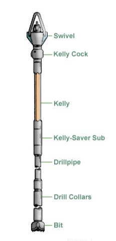
Oil & gas Kelly is a square or hexagonal pipe that fits into the drilling rig rotary table bushing (Rig components). They turn to the right as the rotary table turns. In other words, Kelly’s mission is to transfer energy from the rotary table to the drill string.
We can say that Kelly is a direct connection between the rig’s surface equipment and the oilfield drilling bit and is a vital element of the rotary system. This function is more commonly performed on modern rigs by a top drive system, power swivel, or power sub directly below a conventional swivel. There is usually no drill string rotation when using a downhole mud motor for directional or other applications.
The manufacturing of Kelly in oil and gas rigs will be with either square, triangular, or hexagonal (most common) cross-sections:
The design of their angled surfaces, or drive flats, is to match into kelly bushing so that as the rotary table rotates to the right, the kelly follows its rotation. Kelly’s design has left-hand threads on their top connections and right-hand threads on their bottom connections to allow drill string right-hand rotation.
API Standards For Oil & Gas Kelly
Thanks to The API, API RP 7G, “Recommended Practice for Drill Stem Design and Operating Limits” contains design & manufacturing criteria for Kellys.
Kelly Sizes
The distance across the drive flats determines the size of Kelly (see Figure below)
Kelly Lengths
API Kellys come in two standard lengths:
- 40 ft – 12.2 m overall, with a 37 ft working space;
- 54 ft – 16.5 m overall, with a 51 ft working space.
Connections
Square Kelly Connections
| API Nom. Size (in.) | Top Connection Std. (LH) (in.) | Optional (LH) (in.) | Top OD Std. (in.) | Optional (in) | Bottom Connection Std. (RH) (in.) | Bottom OD Std (in) |
| 2 1/2 | 6 5/8 Reg. | 4 1/2 Reg. | 7 3/4 | 5 3/4 | NC 26 | 3 3/8 |
| 3 | 6 5/8 Reg. | 4 1/2 Reg. | 7 3/4 | 5 3/4 | NC 31 | 4 1/8 |
| 3 1/2 | 6 5/8 Reg. | 4 1/2 Reg. | 7 3/4 | 5 3/4 | NC 38 | 4 3/4 |
| 4 1/4 | 6 5/8 Reg. | 4 1/2 Reg. | 7 3/4 | 5 3/4 | NC 46 | 6 |
| 4 1/4 | 6 5/8 Reg. | 4 1/2 Reg. | 7 3/4 | 5 3/4 | NC 50 | 6 1/8 |
| 5 1/4 | 6 5/8 Reg. | 4 1/2 Reg. | 7 3/4 | 5 3/4 | 5 1/2 FH | 7 |
| 5 1/4 | 6 5/8 Reg. | 4 1/2 Reg. | 7 3/4 | 5 3/4 | NC 56 | 7 |
| **6 | 6 5/8 Reg. | — | 7 3/4 | — | 6 5/8 FH | 7 3/4 |
** 6 in. square oil and gas Kelly, not API.
Hexagon Kellys
| API Nom. Size (in.) | Top Connection Std (LH) (in.) | Top Connection Optional (LH) (in.) | Top OD Std. (in.) | Top OD Optional (in.) | Bottom Connection Std. (RH) (in.) | Bottom OD Std (in.) |
| 3 | 6 5/8 Reg | 4 1/2 Reg | 7 3/4 | 5 3/4 | NC 26 | 33/8 |
| 3 1/2 | 7 5/8 Reg | 5 1/2 Reg | 7 3/4 | 5 3/4 | NC 31 | 41/8 |
| 4 1/4 | 8 5/8 Reg | 6 1/2 Reg | 7 3/4 | 5 3/4 | NC 38 | 43/4 |
| 5 1/4 | 9 5/8 Reg | – | 7 3/4 | – | NC 46 | 6 |
| 5 1/4 | 10 5/8 Reg | – | 7 3/4 | – | NC 50 | 61/8 |
| 6 | 11 5/8 Reg | – | 7 3/4 | – | 5 1/2 FH | 7 |
| 6 | 12 5/8 Reg | – | 7 3/4 | – | NC 56 | 7 |
Dimensions of New Kellys
Square Kelly In Oil & Gas Rigs
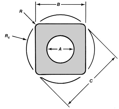
| API Nom Size in | Max Bore A in | Across Flats B (in.) | Across Corner C (in.) | Radius R* (in.) | Radius Rc (in.) |
| 2 1/2 | 1 1/4 | 2 1/2 | 3.25 | 5/16 | 1 5/8 |
| 3 | 1 3/4 | 3 | 3.875 | 3/8 | 1 15/16 |
| 3 1/2 | 2 1/4 | 3 1/2 | 4.437 | 1/2 | 2 7/32 |
| 4 1/4 | 2 13/16 | 4 1/4 | 5.5 | 1/2 | 2 3/4 |
| 5 1/4 | 3 1/4 | 5 1/4 | 6.75 | 5/8 | 3 3/8 |
| **6 | 3 1/2 | 6 | 7.625 | 3/4 | 3 13/16 |
Hexagon Kelly
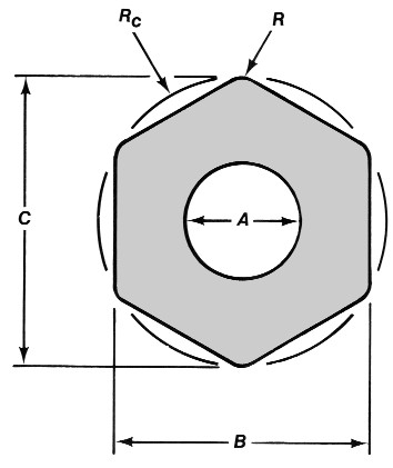
| API Nom. Size (in.) | Max. Bore A (in.) | Across Flats B (in) | Across Corner C (in) | Radius R* (in.) | Radius Rc (in.) |
| 3 | 1 1/2 | 3 | 3.375 | 1/4 | 1 11/16 |
| 3 1/2 | 1 3/4 | 3 1/2 | 3.937 | 1/4 | 1 31/32 |
| 4 1/4 | 2 1/4 | 4 1/4 | 4.781 | 5/16 | 2 25/64 |
| 5 1/4 | 3 1/4 | 5 1/4 | 5.9 | 3/8 | 2 61/64 |
| 6 | 3 1/2 | 6 | 6.812 | 3/8 | 3 13/32 |
- Corner configuration at manufacturer’s option.
Kelly Performance In Oil & Gas Rigs
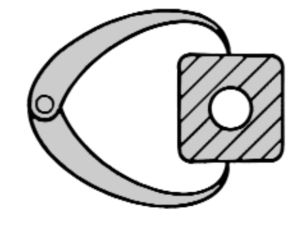
The clearance between Kelly bushing rollers & the flat drive surfaces significantly affects its performance in rotating the drill string. Once this clearance increases, the performance starts to decrease.
The primary cause for Kelly to wear out is the rounding off the drive corners. This wear rate is a function of the fit between the kelly and the rollers in the kelly bushing.
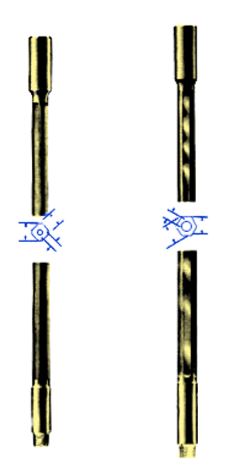
In Figure 7: new Kelly with the new drive assembly. In Figure 8: worn kelly with the worn drive assembly.
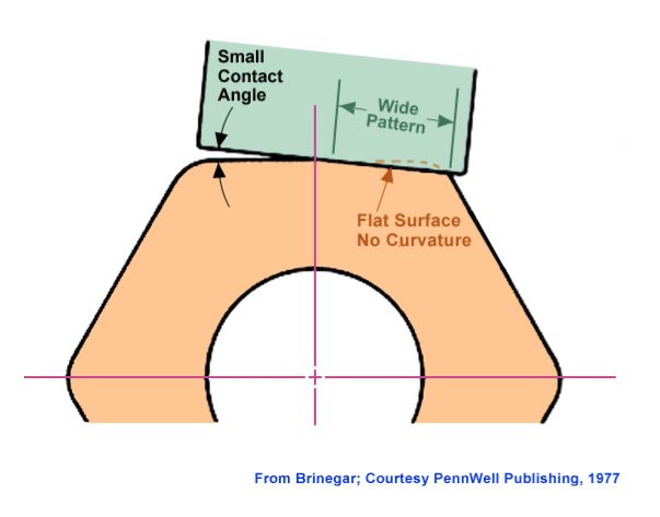
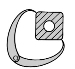
The primary reason for this natural wear rounding is the compressive force of the rollers on the drive flats. Also, rotary torque accelerates this wear.
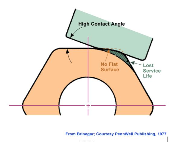
As rounding progresses, it further accelerates the wear process by increasing the clearance and the contact angle between the drive flats and the rollers.
Factors That Affect Oil and Gas Kelly’s Life
For minimal rounding, there must be a close fit between the Kelly and the roller assembly, with the rollers fitting the most prominent spot on the Kelly flats. Manufacturing techniques and rig operating practices play important roles in determining this fit.
Manufacturing Process
The manufacturing of square and hexagonal Kellys are from bars with an “as-forged” drive section or bars with fully-machined drive sections. Machined Kellys are more expensive, but they offer the following features, which tend to result in more extended life:
- Machined Kellys had more closely fit to the roller assembly.
- The machined Kellys, unlike forged Kellys, are not subject to the metallurgical process of decarburization or decarb. Decarburization leaves a relatively soft layer of material (approximately V16″ thick) on the drive surface that can accelerate the rounding process and increase the potential for fatigue cracks;
A square drive section tolerates a greater clearance between flats and rollers than a hexagonal drive section.
Smith – Bottom Hole Assembly Drilling Data Handbook
Note: Because of the high-quality steels used in manufacturing Kellys, fatigue failures are not often a problem.
Rig Operating Practices
To minimize rounding, rig personnel should follow these guidelines (Brinegar, 1977):
- Always use new drive-bushing roller assemblies to break in new Kelly;
- Frequently inspect and periodically replace drive assemblies to ensure holding clearance and contact angle between the kelly and the rollers to a minimum;
- If the rollers are adjustable, adjust them to provide minimum clearance;
- Lubricate drive surfaces to reduce friction and binding at the rollers and to allow the kelly to slide freely through the kelly bushing.
Nevertheless, we should regularly inspect Kellys for cracks and other signs of wear, particularly within the threaded connections, where the flats join the upper and lower upsets and in the center of the drive section.
Oil And Gas Kelly’s Bending Loads
The areas with the highest stress concentration — and, therefore, the most likely locations for fatigue failure — are where the drive flats join the upper and lower upsets.
Generally, the stress level for a given tensile load is less in the drive section of a hexagonal kelly than in the drive section of a square kelly of comparable size. Hexagonal Kellys are thus likely to last longer than square Kellys before failing under a given bending load.
Kellys can become crooked or bent due to improper handling. Examples of mishandling include:
- Dropping the kelly;
- Misaligning the kelly in the rathole, exerting a side pull on the kelly;
- Using poor tie-down practices during rig moves;
- Not using the Kelly Scabbard;
- Using improper loading/unloading techniques.
Depending on the bend’s location, it may cause fatigue damage not only to the kelly but to the rest of the drill string and can also result in uneven wear on the kelly bushing.
Unusual side motions or swaying of the swivel are good indicators of crooked Kelly. A good field service shop has equipment for straightening bent Kellys, making this an easily corrected problem.
When Picking Up a New Kelly In Oil & Gas Rig
Before picking up a new Kelly, check your Kelly bushing. The rollers, pins, or bearings may need replacing to return the drive assembly to like-new status. Also, check the bushing body for journal area wear and body spreading. A loose-fitting drive unit can badly damage a new Kelly on the first well drilled. Remember to lubricate Kelly drive surfaces.
Inspection
At regular intervals, have Kelly’s threaded connections checked by your inspector. Remember, these connections, like drill collar connections, are subject to fatigue cracks. Also, the drive section and upset areas should be inspected for cracks and wear patterns.
Kelly Saver Subs
The Kelly saver sub protects the lower Kelly connection from wear caused by making and breaking the drill pipe connection each time a joint is drilled down. They also protect the top joint of the casing against excessive wear, if fitted with a rubber protector and provide an area to turn on when making up or breaking out the kelly. When you need a new stabilizer rubber, an old sub reworked, or a brand new one, mention this to your service company before you pick up that new Kelly.
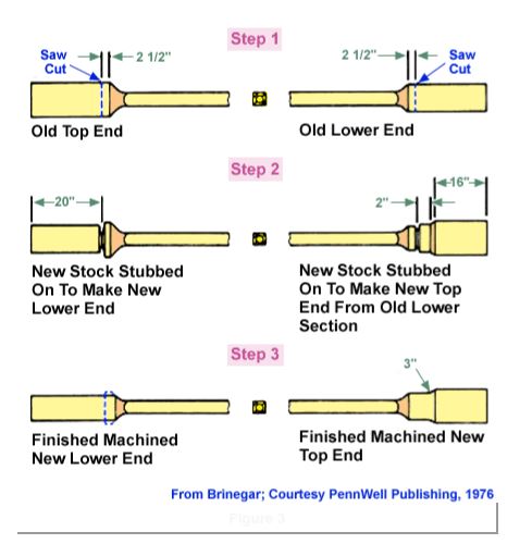
What Can You Do With Old Kelly In Oil & Gas Rig?
Use the Other Corners
We can change ends on the kelly by employing a temperature-controlled stubbing procedure. This allows Kelly to drive against new corners. Welding is done only in the large diameter round sections. We do not recommend welding on the hexagonal or square surfaces of the kelly.
Remachine Drive Surfaces
With the Heli-Mill, we can machine Kelly. This amounts to taking a clean-up cut on each driving surface. Note: Oversize rotary drive rollers are used with re-machined kelly. The bore diameter of the kelly must be small enough to allow enough wall thickness for re-machining.
Straightening an Old Kelly
A bent kelly takes a beating as it is forced through the rotary drive bushings. Some repair centers have straightening presses to straighten Kelly and accurately check the run-out.
If Your Kelly is Too Far Gone, Your best bet is to buy a new kelly.
Reversing The Ends
To a certain point, worn kelly can be repaired by reversing the ends ( Figure 3 ) or re-machining it to a smaller size.
References:
- Smith – Drilling Assembly Handbook
- API RP 7G, “Recommended Practice for Drill Stem Design and Operating Limits“