The BOP rams are the result of some eighty years of development in the BOP stack system. The first BOP ram was developed in the early 1900s. The ram preventer will only seal on the specific condition for which the ram block is designed.
Rams are interchangeable between ram-type preventers of the same design and pressure rating. Casing rams are usually substituted for pipe rams before casing running or liner running operations.
Most pipe rams can be locked in the closed position, operated manually and hydraulically, and support the weight of the entire drill string. Pipe rams cannot be installed upside down because they are designed to hold pressure from one direction only.
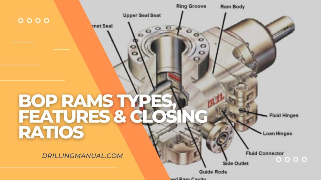
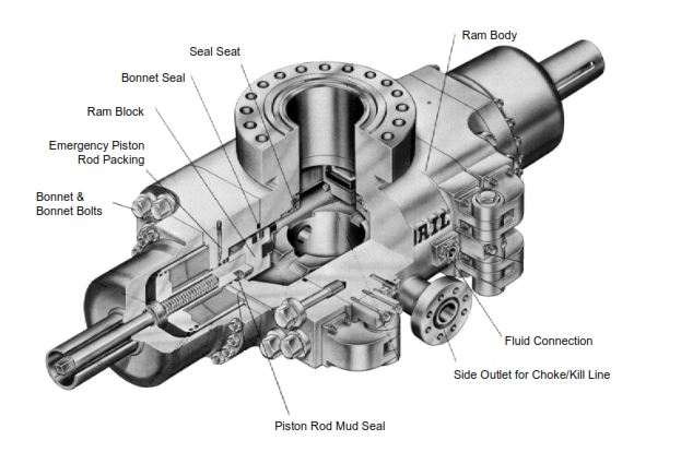
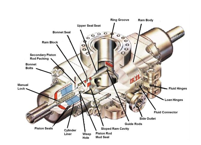
BOP Rams Components
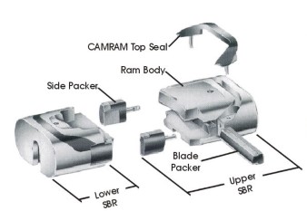
The major parts of the blowout ram preventer consist of:
- The ram body houses all the parts that allow the ram preventer to operate.
- The fluid connection is the port for the hydraulic fluid connection that operates the piston.
- the side outlet which is a connection built into the ram body that allows fluid to be circulated into or out of the wellbore.
- The piston rod mud seal is a secondary seal that keeps the drilling fluid types (OBM – WBM) from contaminating the inner seals on the piston rod.
- The bonnet which is secured by the bonnet bolts allows access to the ram body to change the ram block.
- The emergency piston rod packing is a grease injection port that allows a seal to be made on the piston rod should the primary seal begin to leak.
- The bonnet seal is an elastomeric seal that prevents wellbore fluid under pressure from escaping.
- The seal seat is a replaceable part that stops wear on the ram body by the operation of the ram block. It can be replaced in the field.
BOP Rams Types
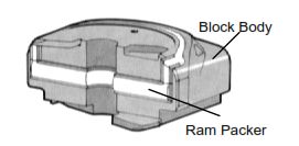
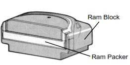
There are two types of ram blocks with packer seals:
- Ram Block that seals on pipe
- Ram Block that can close on open hole.
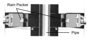
Pipe Rams – Seal on the pipe
Ram blocks that seal on pipe (Figure 3) or wireline in the hole. The block is specifically designed for a particular size of drill pipe, tubing, casing, or wireline.
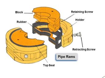
Ram blocks designed for pipe should not be closed without pipe (drill pipe – heavy weight drill pipe – Casing) in them because the sealing elements may be damaged by extrusion.

Variable Pipe Ram For BOP
The pipe ram block can also be a variable bore block (Figure 7) which can seal on a size range.
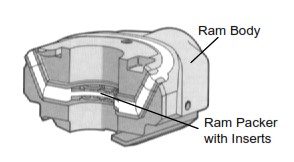
Variable rams became available by 1979. Also, these rams extend the versatility of the ram-type preventer by sealing on pipes of various sizes. This flexibility could eliminate the need for changing rams when running a tapered drill string or when testing with tubing. Variable rams use steel fingers that move inward to seal around pipe smaller than the ram body.
In general, all manufacturers of ram preventers offer variable bore rams (Figure 7) which can close and seal on a range of pipe diameters. These rams can be especially useful when a tapered string is in use or when substructure space limitations restrict the addition of another ram preventer. Also if an aluminum drill pipe is being used an effective seal cannot always be assured with regular pipe rams because the diameter of the pipe is larger near the tool joints than at the middle of the joint.
Variable bore rams have limited hang-off potential, depending on the pipe size on which they are sealing. For example, Cameron variable bore rams (13-5/8” U for 5” to 2-7/8”) will support 450,000 pounds of 5” drill pipe or 150,000 pounds of 3-1/2” drill pipe. Most variable bore rams are constructed in a similar fashion with the key element being a feedable rubber packer.
Blind Rams
Generally, there are two types of rams that do not have pipe openings and can be closed on open hole. The most widely used is the blind rams (Figure 8);
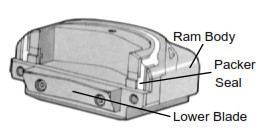
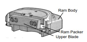
Shear BOP Ram
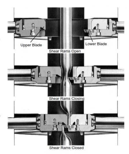
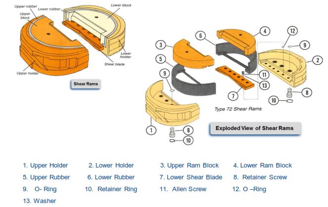
The other type of BOP ram that we can close in the open hole is the shear ram. The shear ram (Figures 9 & 10) is designed to cut through the tubing, drill pipe, or casing, and in addition, it can seal on an open hole (Shear rams are used mostly in a subsea stack).
Shear/Blind BOP Ram
Shear/blind rams include a single-piece body with an integrated cutting edge to shear the pipe that is in front of the ram. Then, by bending the lower section of the pipe, the rams can close and provide a seal. It can also function as a blind ram and close & seal when there is no pipe in the hole. The operating pressure that you will need to shear pipe is 3,000 psi and the maximum size of pipe that you can cut is 5 ½” OD. Actually, the advantage of the shear ram is that you can use it many times without making damage to its cutting edge. Remember, we can always utilize it as a blind type during drilling operations
Casing Rams
The casing rams are available to provide pack-off on the casing annulus when running casing. Casing shear rams are also available but may require “ booster ” pistons or higher closing pressure to assure shearing of certain-sized casings.
BOP Rams Features
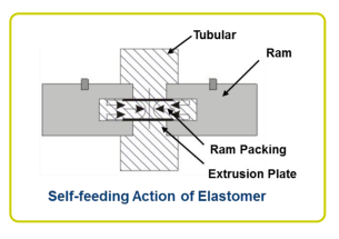
Self-Feeding Elastomer Packing
The front elements of ram seals have steel “extrusion” plates bonded to the rubber. As the rams close the steel plates meet and begin to force elastomer to pack into the sealing area. When stripping operations, the front face of the ram sealing element will wear. This self-feeding feature will allow the sealing to be maintained during the stripping operation.
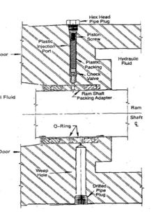
Secondary BOP Ram Shaft Seal
On many ram preventers, there is a “weep hole” located on the underside of the preventer body. This hole is lined up with the “travel” of the ram. The weep hole is actually in line with secondary rod shaft seals and is there to indicate leaks in those seals. If needed, the cap screw is removed, and using an Allen wrench, the plastic sealant is injected through a check valve and around the ram shaft between seals to temporarily stop the leak.

Secondary or Emergency Mud Seal
- The figure shows the secondary mud seal on an NL Shaffer ram-type BOP.
- The secondary seal is a plastic packing injected into an exterior groove around the ram shaft.
- As more plastic is injected and seals off between the ram shaft and the interior body of the preventer.
- The secondary mud seal should only be used in an emergency and is only usable once.
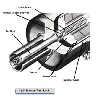
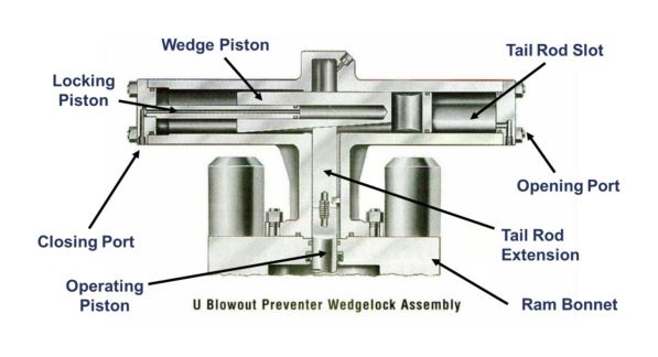
BOP Ram Locking Device
Many rams feature a manual locking device. The lock is activated after the ram is in the fully closed position. In this case, a ram manufactured by Hydril, is locked by clockwise rotation of the tail rod. The locking device travels down the lead screw and contacts the back of the piston mechanically locking it into the closed position. The locking device must be backed out in order to re-open the ram.
Should hydraulics fail, the locking device can be used to close the ram. If this is done, the ram can only be re-opened hydraulically.
U Blowout Preventer Wedgelock Assembly
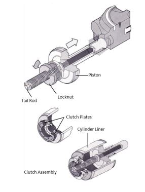
Hydril MPL Ram Lock
The MPL Locking mechanism is controlled by a unidirectional clutch and lock nut. The clutch maintains the nut and ram in a locked position until the clutch is disengaged by applying hydraulic opening pressure. This disengages the clutch plates permitting the lock nut to freely rotate and the ram to open. The ram will stay closed and locked even if the closing pressure is bled to 0 psi.
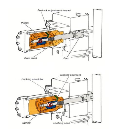
Shaffer Pos – Lock Ram Lock
As closing pressure is applied the piston along with the locking cone moves inward and closes the ram. When the piston reaches the fully closed position, the locking segments slide toward the piston OD over the locking shoulder because the locking cone is forced inward by closing hydraulic pressure and spring action.
The locking cone holds the locking segments in position. It acts like a second piston inside the main piston and is forced inward by closing pressure and outward by opening pressure. As opening pressure is applied, the locking cone moves outward causing the locking segments to slide toward the piston ID along a tapered locking shoulder. The piston then freely moves to the fully open position.
One note of interest – the Pos-Lock may not allow for self-feeding of ram rubber elements in worn rams as it locks in one position only.
Closing Opening Ratios For BOP Rams
In the below table, there are different closing and opening ratios for different Ram BOPs in the market.
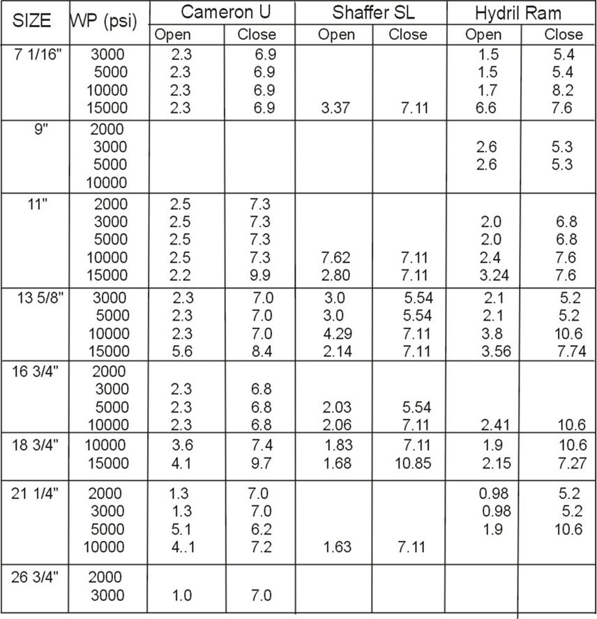
| SIZE | WP (psi) | CAMERON ‘U’ OPEN | CAMERON ‘U’ Close | SHAFFER ‘SL’ Open | SHAFFER ‘SL’ Close | HYDRIL RAM Open | HYDRIL RAM Close |
| 7 1/16” | 3,000 | 2.3 | 6.9 | – | – | 1.5 | 5.4 |
| 7 1/16” | 5,000 | 2.3 | 6.9 | – | – | 1.5 | 5.4 |
| 7 1/16” | 10,000 | 2.3 | 6.9 | – | – | 1.7 | 8.2 |
| 7 1/16” | 15,000 | 2.3 | 6.9 | 3.37 | 7.11 | 6.6 | 7.6 |
| 9” | 2,000 | – | – | – | – | – | – |
| 9” | 3,000 | – | – | – | – | 2.6 | 5.3 |
| 9” | 5,000 | – | – | – | – | 2.6 | 5.3 |
| 9” | 10,000 | – | – | – | – | – | – |
| 11” | 2,000 | 2.5 | 7.3 | – | – | – | – |
| 11” | 3,000 | 2.5 | 7.3 | – | – | 2 | 6.8 |
| 11” | 5,000 | 2.5 | 7.3 | – | – | 2 | 6.8 |
| 11” | 10,000 | 2.5 | 7.3 | 7.62 | 7.11 | 2.4 | 7.6 |
| 11” | 15,000 | 2.2 | 9.9 | 2.8 | 7.11 | 3.24 | 7.6 |
| 13 5/8” | 3,000 | 2.3 | 7 | 3 | 5.54 | 2.1 | 5.2 |
| 13 5/8” | 5,000 | 2.3 | 7 | 3 | 5.54 | 2.1 | 5.2 |
| 13 5/8” | 10,000 | 2.3 | 7 | 4.29 | 7.11 | 3.8 | 10.6 |
| 13 5/8” | 15,000 | 5.6 | 8.4 | 2.14 | 7.11 | 3.56 | 7.74 |
| 16 3/4” | 2,000 | – | – | – | – | – | – |
| 16 3/4” | 3,000 | 2.3 | 6.8 | – | – | – | – |
| 16 3/4” | 5,000 | 2.3 | 6.8 | 2.03 | 5.54 | – | – |
| 16 3/4” | 10,000 | 2.3 | 6.8 | 2.06 | 7.11 | 2.41 | 10.6 |
| 18 3/4” | 10,000 | 3.6 | 7.4 | 1.83 | 7.11 | 1.9 | 10.6 |
| 18 3/4” | 15,000 | 4.1 | 9.7 | 1.68 | 10.85 | 2.15 | 7.27 |
| 21 1/4” | 2,000 | 1.3 | 7 | – | – | 0.98 | 5.2 |
| 21 1/4” | 3,000 | 1.3 | 7 | – | – | 0.98 | 5.2 |
| 21 1/4” | 5,000 | 5.1 | 6.2 | – | – | 1.9 | 10.6 |
| 21 1/4” | 10,000 | 4.1 | 7.2 | 1.63 | 7.11 | – | – |
| 26 3/4” | 2,000 | – | – | – | – | – | – |
| 26 3/4” | 3,000 | 1 | 7 | – | – | – | – |