
Application
During operations on drilling or producing well, a sequence of events may require tubing, casing, or drill pipe to be run or pulled while annular pressure is contained by blowout preventers; such practice is called “stripping operation”. Stripping is normally considered an emergency procedure to maintain well control; however, plans for certain drilling, completion, or well workover operations may include stripping to eliminate the necessity of loading the well with fluid.
Stripping Operation Equipment
Stripping techniques vary, and the equipment required depends upon the technique employed. Each stripping operation tends to be unique, requiring adaptation to particular circumstances. Therefore, the equipment and the basic guidelines discussed herein are necessarily general in nature.
The stripping requires drilling surface equipment which simultaneously:
- permits pipe to be pulled from or run into a well,
- provides a means of containing and monitoring annular pressure, and
- permits measured volumes of fluid to be bled from or pumped into the well.
The stripping requires subsurface equipment which simultaneously:
A. prevent pressure entry or flow into the pipe being stripped. This equipment should either be removable or designed so that its presence will not interfere with operations subsequent to stripping. The well site drilling supervisor and crew must have a thorough working knowledge of all well control principles and equipment employed for stripping. Equipment should be rigorously inspected, and, if practicable, operated prior to use.
For stripping operations, the primary surface equipment consists of
- blowout preventers
- closing units
- chokes
- pumps
- gauges
- Drilling trip tanks (or other accurate drilling fluid measuring equipment).
Blow Out Preventer
The number, type, and pressure rating of the blowout preventers required for stripping are based on anticipated or known surface pressure, the environment, and the degree of protection desired. Often the blowout preventer stack installed for normal drilling is suitable for low-pressure stripping if spaced so that tool joints or couplings can be progressively lowered or pulled through the stack, with at least one sealing element closed to contain well pressure.
Annular preventers are most commonly employed for stripping because tool joints and some couplings can be moved through the preventer without opening or closing the packing element.
Wear of the packing element while drilling limits the sole use of this preventer if high annular pressure must be contained while stripping. To minimize wear the closing pressure should be reduced as much as possible and the element allowed to expand and contract (breathe) as the tool joint passes through.
Lubrication of the pipe with a mixture of oil and graphite or permitting a small leakage of annular fluid will reduce wear on the packing element. A spare packing element should be at the well site during any stripping operation.
The Ram type preventers or combinations of ram and annular preventers are employed when pressure and/or Configuration of the coupling could cause excessive wear if the annular preventer were used alone. Ram preventers must be opened to permit the passage of tool joints or couplings. When stripping operation between preventers, provision should be made for pumping into and releasing fluid from the space between preventers. Pressure across the sealing element should be equalized prior to opening the preventer to reduce wear and to facilitate the operation of the preventer. After equalizing the pressure and opening the lower preventer a volume of drilling fluid equal to that displaced as the pipe is run into or pulled from the well should be, respectively, bled from or pumped into the space between the preventers.
Chokes
Chokes are required to control the release of fluid while maintaining the desired annular pressure. Adjustable chokes which permit fast, precise control should be employed. Parallel chokes which permit isolation and repair of one choke while the other is active are desirable on lengthy stripping operations. Because of the severe service, spare parts or spare chokes should be on location.
Pumps
A pump truck or skid-mounted pump is normally employed when stripping out. The relatively small volume of drilling fluid required to replace the pipe capacity and displacement of each stand or joint of the pipe may be accurately measured and pumped at a controlled rate with such equipment. Well fluid from below the preventer should not be used to equalize pressure across the stripping preventer.
Trip Tank
A trip tank or other method of accurately measuring the drilling fluid bled off, leaked from, or pumped into the well within an accuracy of the one-half barrel is required.
The lowermost ram should not be employed in the stripping operation. This ram should be reserved as a means of shutting in the well if other components of the blowout preventer stack fail. It should not be subjected to the wear and stress of the stripping process in drilling.
The options available if there are a swabbed influx OR if the well starts flowing during a trip:
- If well is not flowing, make tripping pipe back to bottom keeping a careful check on returns. Then circulate influx out of hole.
- If well is flowing and you followed shut in procedures and the gas is percolating with the drilling bit a long way off bottom and tight hole conditions have been experienced, then consider doing a volumetric bleed.
- If well is flowing and is shut in and the gas is percolating with the bit a long way off bottom and tight hole conditions have been experienced, then consider bullheading.
- If well is flowing and is shut in and the gas is percolating and no problems are anticipated in stripping back to bottom, then consider volumetric stripping operation to get drilling bit to bottom. Circulate influx out using first circulation of Driller’s Method.
Note: A swabbed kick well can be most effectively killed with a bit on the bottom. So every effort must be made to get bit safely back on the bottom.
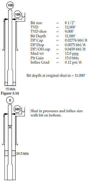
Example of Volumetric Stripping Operation
Well details
Shut in procedure for a swabbed kick while tripping- Fast shut-in
- Stab safety valve (kellycock).
- Close safety valve.
- Open HCR fail safe valves.
- Close annular.
- Read casing pressure and if possible read drill pipe pressure.
- Stab inside BOP stack (Gray valve).
- Open safety valve.
- Do stripping calculations, prepare stripping sheet.
- Reduce annular pressure and start stripping drill pipe.
Note: The above procedure (steps 1 through 5) assumes there is no float or non-return valve in the drill string.
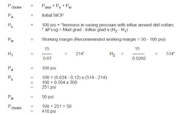
Stripping Operation Calculation for safety margins and working margins:
Note:
- If the gas is not migrating while stripping, only theoretical bleed off will be seen in strip tank.
- If gas is migrating then any excess bleed off is due to migration.
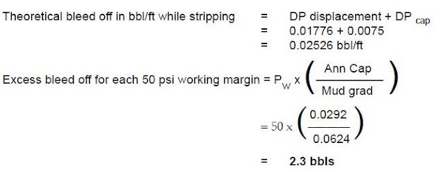
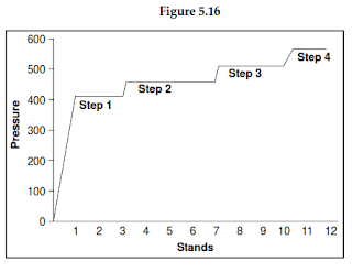
When excess bleed off is ± 2.3 bbls, then build in another 50 psi working pressure. Refer to Volumetric Stripping chart
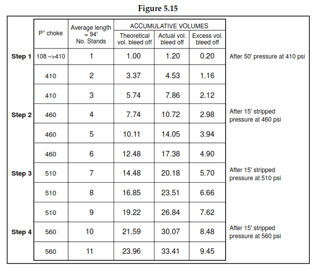
Step 1: Allow casing pressure to increase to calculated Pchoke pressure while stripping the first stand, then hold casing pressure constant by bleed off at choke.
Note: The casing pressure may not rise straight away because the gas has to be compressed. It may take 2 – 3 stands before a pressure build-up is seen.
Step 2, 3, and 4: With theoretical bleed already calculated, record actual bleed, when the difference between the actual and theoretical bleed is 2.3 bbls allow annulus pressure to increase by Pw (50 psi).
With bit on bottom
Casing pressure reads 560 psi, gas influx has expanded by 9.45 bbls and if it was possible to read drill pipe pressure it would read zero with drill pipe full of mud. The influx should now be circulated out using the auto choke.
Note: No kill mud will be required as this is a swabbed kick.