Mud Engineers & drilling engineers need to have quick drilling fluid calculations equations to help them while they are on the rig. In this article, we will have a simple guide for the most used equations for drilling mud preparations, system, displacement, volumes, etc.
Density and Specific Gravity Calculations For mud
The density of a material is defined as its mass per unit volume and is usually expressed in units of g/cm3, kg/m3 or, commonly in oilfield usage for liquids, lb/US gal. As an example, the density of (barite) is 4 g/cm3. Specific gravity (SG) is a unitless measure of relative density (the density of a material divided by the density of a reference substance).
The reference substance is almost always water, which has a density very close to 1 g/cm3, and so the specific gravity of a material is very similar numerically to the density of that material, but for accurate work, it is necessary to quote the temperatures at which measurements are made.
To determine the SG of a material, divide the density of the material by the density of water. Note that for accurate work, water density depends on temperature and the reference temperature should be quoted. Common reference temperatures are 39°F (4°C) and 68°F (20°C); the difference in the density of water at these two temperatures is approximately 0%.
Two figures are widely used in the drilling fluids industry for the density of water in oilfield units (lb/US gal). The figure of 45 assumes that the temperature of measurement is 39°F (4°C), which is the figure adopted by the API. The figure of 3 assumes that the temperature of measurement is 68°F (20°C) and this is the figure used throughout this article. Using this figure, a 15.0 lb/gal mud has an SG of 1.8.
Equation 1
Volume, Capacity, and Displacement Calculations for Mud Engineer
Volume and capacity have the same units but are not always equal. For example, a mud pit of 300 bbl capacity might only contain a volume of 200 bbl. Displacement is the volume of fluid displaced when the drill string is run into the wellbore full of fluid.
Volume Calculations For drilling fluid
Mud system volume = the total volume of what is in the active pits plus that volume in the hole
Total mud volume = pit volume + hole volume
Pump output volume = that volume adjusted for pump efficiency. Duplex mud pumps have an approximate efficiency of 85–95%, whereas triplex pumps have an approximate efficiency of 90–98%.
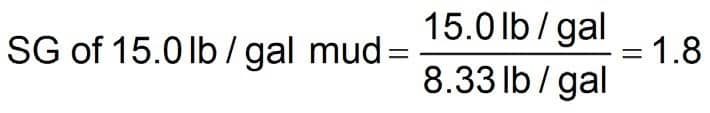
The following two drilling equations, which are used by the mud engineer, calculate pump output Q at 100% volumetric efficiency. The constant, Ve, can be adjusted to calculate the bbl/stroke, gal/stroke, or liter/stroke.
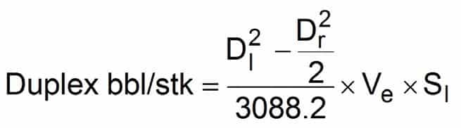
Where:
- Dl = Liner diameter, inches
- Dr = Rod diameter, inches
- Ve = Volumetric efficiency (decimal fraction)
- Sl = Stroke length, inches
Pit Capacity Determination For Mud Tanks
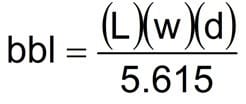
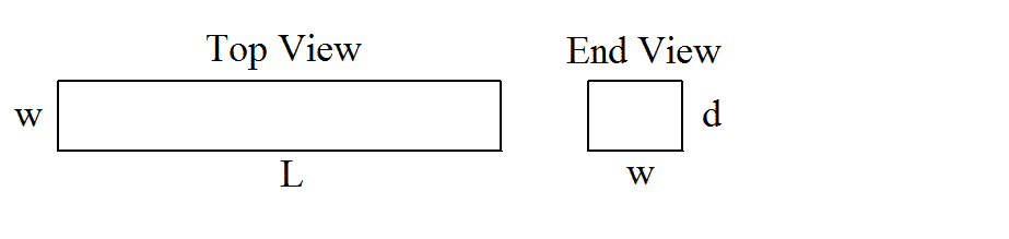
The most common container for the surface volumes is rectangular pits with vertical sides and flat bottoms. Other types of pits that may be encountered are rectangular pits with sloping sides and circular or elliptical cylindrical tanks. ( see also the Circulating system article). All dimensions the drilling/mud engineers use in the following calculation formulae are in feet.
Rectangular Mud Tanks with Flat Bottoms
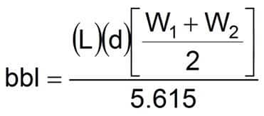
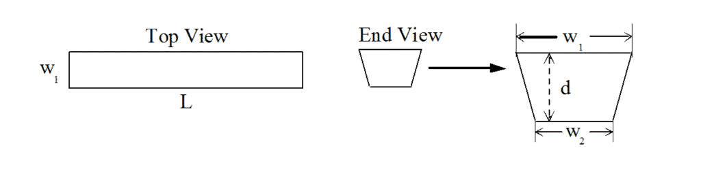
Rectangular Fluid Tanks with Sloping Sides
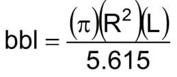
Circular Mud Cylindrical Tanks
For mud engineer calculations, Upright Cylindrical Tanks

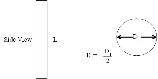
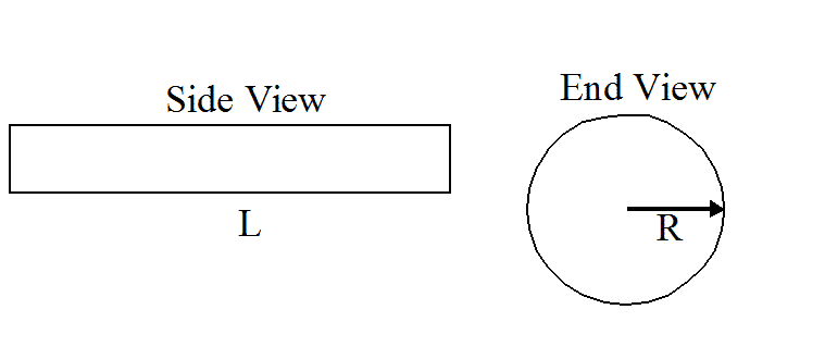
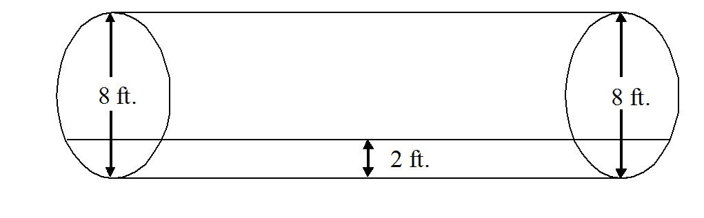
Horizontal Cylindrical Tanks
i. Determine the total tank capacity.
Equation 7
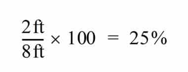
ii. Determine the percentage of tank diameter that is filled. If an 8 ft diameter tank is filled to a 2 ft level, it is filled to 25% of its diameter.
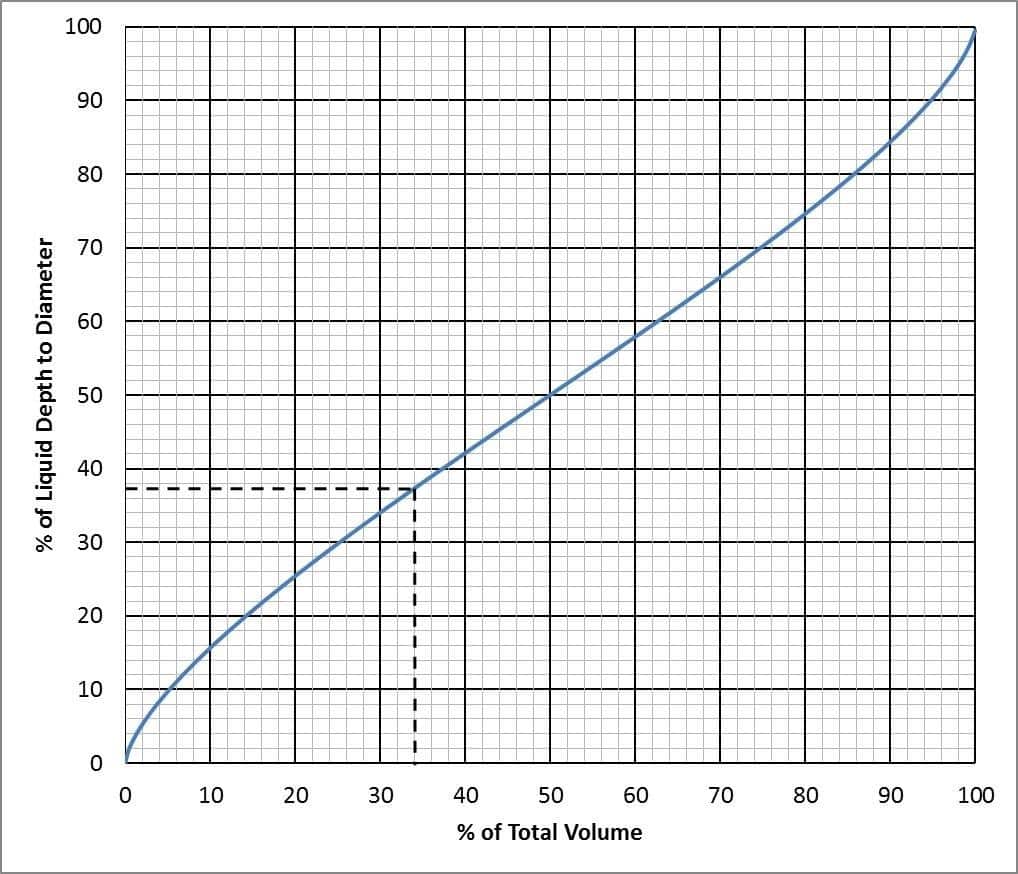
iii. Use the following graph to determine the tank volume based on percentage of tank diameter filled.
Example:
Diameter = 4 ft
Length = 20 ft
Fluid height = 1 ft
Total tank capacity = (34 × 22 × 20)/515 = 443 bbl
Percentage of liquid depth to diameter = (1 ÷ 4) × 100 = 37
From the graph, a percentage of 37 indicates 34% of capacity
Percentage of total capacity = 04×44 = 15 bbl fluid in tank
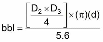
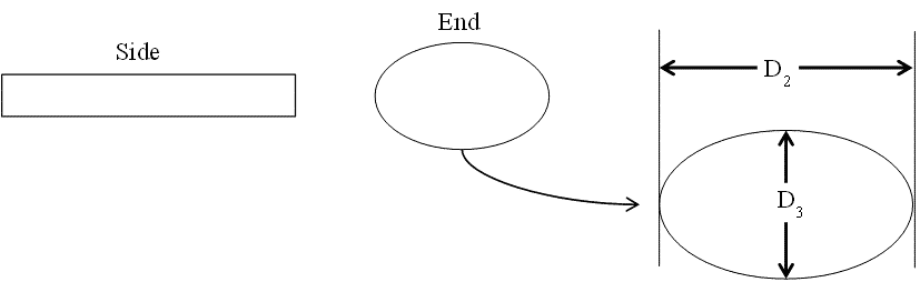
Elliptical Cylindrical Tanks
Equation 8
Drilling Mud Capacity and Displacement Calculations(Drill string and Hole)
Nomenclature
- Outside diameter, in. — OD
- Inside diameter, in. — ID
- Hole diameter, in. — Dh
- Annular outer pipe diameter, in. — D
- Annular inner pipe diameter, in. — d
- Closed-ended pipe — CE
- Open-ended pipe — OE
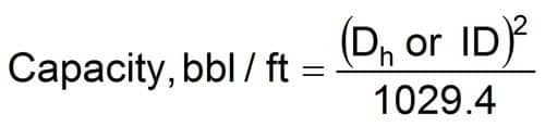
Capacity
For drilling/mud Engineer to do calculations of the capacity of drill pipe, drill collars, Heavy weight drill pipe, Casing, other tubular, wellbore (cased or open) (Download Now Capacity Calculator Sheet): Diameter of wellbore = Dh or casing ID are used to solve the following equation.
Equation 9
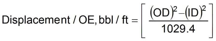
Displacement
Open-ended pipe
As related to drill pipe, drill collars, and other tubulars is the volume of fluid that the pipe displaces by its wall thickness. Pipe OD and ID are used in the following equation:
Equation 10
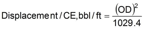
Closed-ended pipe
As related to drill pipe, drill collars and other tubular is the volume of fluid that is displaced by its wall thickness plus the internal capacity of the pipe.
Equation 11
Open Hole and Casing Volume (Without Pipe)
Equation 12

or Equation 13
Note Drilling / Mud Engineer shall use inside diameter (ID) for casing and bit diameter for open-hole calculations. Do not allow for open-hole washout unless values are known from fluid (mud) logging data or caliper logs. Annular capacity tables or casing capacity tables can be used in lieu of the formulae.
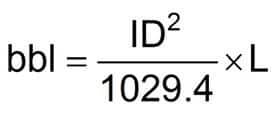
Pipe Capacity
Equation 14
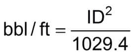
or Equation 15

Where:
ID = Inside diameter of drillpipe. (in.)
Use equivalent IDs from pipe tables in this section.
L = Length (ft)
Pipe Displacement Obtained from Pipe Tables
Because of the varying thicknesses of the various types of tool joints, read displacements from pipe tables rather than calculate them, unless tool joint specifications are available.
Annular Volume
Equation 16
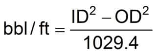
or
Equation 17
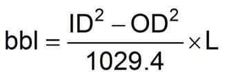
Where:
- ID = Inside diameter of casing or bit diameter (in.)
- OD = Outside diameter of drillpipe or drill collars (in.)
- L = Annular section length (ft)
Annular Velocity
Equation 18
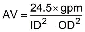
Where:
- AV = Annular velocity, (ft/min)
- gpm = gal/min
- ID = Inside diameter of the hole or casing (in.)
- OD = Outside diameter of the pipe or collars (in.)
Bottoms Up (Strokes or Time)
Equation 19
Total Circulating Displacement (Strokes or Time)
Equation 20
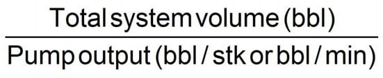
Where:
- Total system volume = Surface volume + Pipe capacity + Annular volume
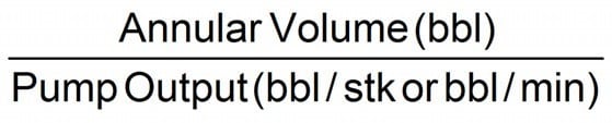
Hole Volume Displacement (Strokes or Time)
Equation 21
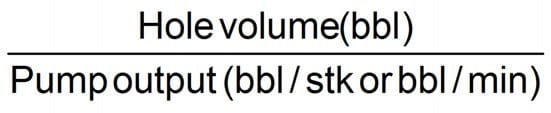
Where:
- Hole volume = Annular volume + Drillpipe capacity
- Hole volume = Open hole capacity – Drillstring displacement
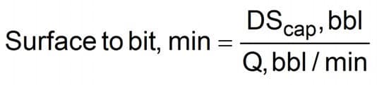
Drilling Mud Circulating Time Calculations
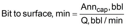
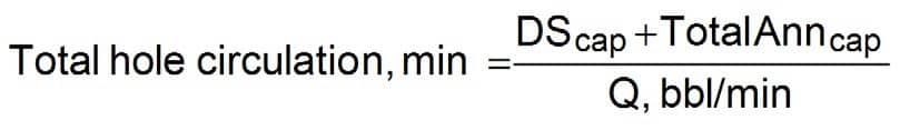
Nomenclature
- Annulus capacity — Anncap
- Pump output — Q
- Drill string capacity — DScap
Equation 22
Equation 23
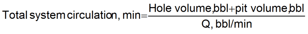
Equation 24
Density and Volume Calculations
Density Increase Using (Barite)
Equation 25
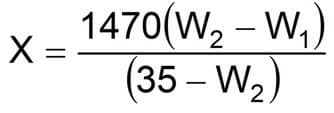
Where:
- X = Sacks of BAR/100 bbl fluid (100 lbm sacks)
- W1 = Initial fluid density (lbm/gal)
- W2 = Desired fluid density (lbm/gal)
If using Barite 4, replace 1470 with 1,435 and 35 with 34 in the above equation.
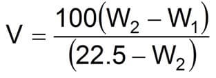
Volume Increase Using (Barite)
Equation 26
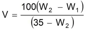
Where:
- V = Volume increase/100 bbl fluid
- W1 = Initial fluid density (lbm/gal)
- W2 = Desired fluid density (lbm/gal)
If using Barite 4, replace 35 with 34 in the above equation.
Density Increase Using (Hematite)
Equation 27
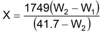
Where:
- X = Sacks of DENSIMIX/100 bbl fluid (100 lbm sacks)
- W1 = Initial fluid density (lbm/gal)
- W2 = Desired fluid density (lbm/gal)
Volume Increase Using (Hematite)
Equation 28
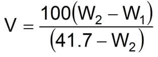
Where:
- V = Volume increase/100 bbl of fluid
- W1 = Initial fluid density (lbm/gal)
- W2 = Desired fluid density (lbm/gal)
Density Increase Using (CaCO3)
Equation 29
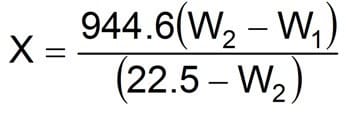
Where:
- X = Sacks of MIL-CARB/100 bbl fluid (100 lbm sacks)
- W1 = Initial fluid density (lbm/gal)
- W2 = Desired fluid density (lbm/gal)
Volume Increase Using (CaCO3)
Equation 30
Where:
- V = Volume increase/100 bbl of fluid
- W1 = Initial fluid density (lbm/gal)
- W2 = Desired fluid density (lbm/gal)
Weight Reduction with Freshwater
Equation 31
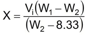
Where:
- X= bbl of water required
- Vi= Initial volume (bbl)
- W1 = Initial fluid density (lbm/gal)
- W2 = Desired fluid density (lbm/gal)
Weight Reduction with Oil
Equation 32
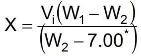
The specific gravity of oil = 0.84
Where:
- X = bbl of oil required
- Vi = Initial volume (bbl)
- W1 = Initial fluid density (lbm/gal)
- W2 = Desired fluid density (lbm/gal)
Mixing Liquids of Different Densities
Equation 33
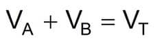
Equation 34
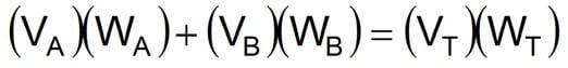
Where:
- VA = Volume of first fluid (bbl)
- VB = Volume of second fluid (bbl)
- VT = Final volume (bbl)
- WA = Density of first fluid (lbm/gal)
- WB = Density of second fluid (lbm/gal)
- WT = Density of combined fluids or final weight (lbm/gal)
Note Drilling / Mud Engineer shall know that this drilling fluid calculations formula assumes fluids are totally miscible, no precipitation reactions occur, and fluids are of comparable salinity. This equation does not apply to the mixing of high-density brine fluids.
Fluid Density Increase for Slugging Pipe
Equation 35
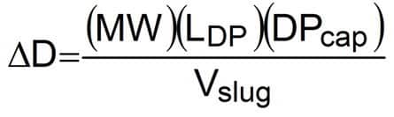
Where:
- ∆D = Fluid density increase (lb/gal)
- MW = Current fluid density (lb/gal)
- DPcap = Drillpipe capacity (bbl/ft)
- Vslug = Slug volume, usually 30 to 50 bbl
- LDP = Desired length of dry pipe, usually 500 to 800 ft
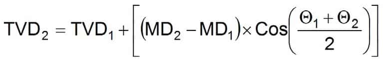
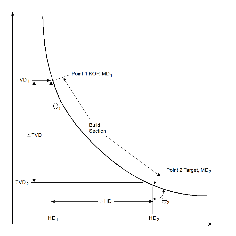
Vertical Depth vs. Deviated Hole Calculations
True vertical depth (average angle method)
Equation 36
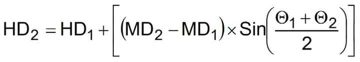
Horizontal displacement (average angle method)
Equation 37
Kick-off point determination
Equation 38
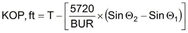
Where (all depths in feet):
- TVD1 = True vertical depth at point 1
- TVD2 = True vertical depth at point 2
- MD1 = Measured depth at point 1
- MD2 = Measured depth at point 2
- HD1 = Horizontal displacement at point 1
- HD2 = Horizontal displacement at point 2
- θ1 = Deviation at point 1
θ2 = Deviation at point 2
- T = Target depth
- BUR = Build-up rate (°/100 ft)
Note This method of drilling fluid calculations assumes that the course length between point 1 and point 2 is a straight line. The direction and inclination are also assumed to be the averages of the values measured at each point. The method will be less accurate when applied over long course lengths, but it is a good approximation for most drilling / mud engineering calculations.
Drilling mud / fluid Calculations (mud engineer calculations) for deviated wells must use measured depth when calculating volumes and vertical depth when calculating equivalent fluid weights.
Buoyancy
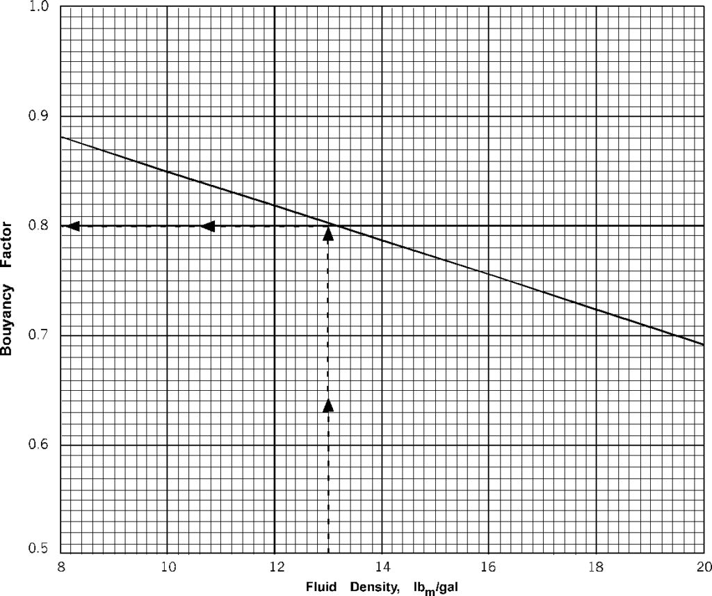
Perfect