Several procedures are available for improving mud displacements in any oil rig or gas rig and they need to be considered when planning a displacement in order to prevent or minimize fluid contamination. However, operational factors may restrict the use of some of the following procedures:
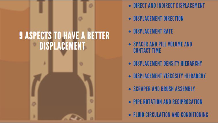
- Direct and Indirect Displacement
- Displacement Direction
- Displacement Rate
- Spacer and Pill Volume and Contact Time
- Displacement Density Hierarchy
- Displacement Viscosity Hierarchy
- Scraper and Brush Assembly
- Pipe Rotation and Reciprocation
- Fluid Circulation and mud Conditioning
1 Direct and Indirect Mud / Fluid Displacements
The nature of the mud displacement in oil rig and whether it is performed in open hole or cased hole usually determines the choice between a direct or indirect displacement. A direct displacement occurs when one fluid is displaced to another fluid in a single circulation, using various pills and spacers to separate the fluids and/or clean the hole (Read more about : hole cleaning). An indirect mud displacement occurs when one fluid is displaced to an intermediate fluid first (usually water or seawater), which is then circulated until the hole is clean before displacing to the final fluid.
Indirect mud displacements are usually performed in the cased hole, when the reservoir is isolated, and when a plentiful supply of water is available (e.g. seawater). An inflow test is usually performed to confirm safe isolation of the reservoir when this has been achieved using a production packer assembly. Indirect mud displacements are beneficial for well clean-ups because water can be circulated at high flow rates until tubular surfaces are clean. Additional surfactant pills and viscous spacers can also be circulated to ensure that the wellbore is clean before displacing to completion brine.
Direct mud displacements must be performed in the open hole because hydrostatic pressure has to be maintained to control formation pressures (read also: Causes Of Abnormal Pressure). However, direct displacements are also performed in the cased hole, and various pills and spacers are available for improving the effectiveness of these displacements. Displacements from Water Based Mud to Oil Based Mud are not so critical because oil-based fluids can tolerate contamination due to water-based fluids and residual solids, so a direct mud displacement will obviously save rig time.
2 The Mud Displacement Direction In Oil Rig
Fluids can be pumped down the Drill Pipe (API Drill Pipe Specs) and up the annulus (conventional circulation), or down the annulus and up the drill pipe (reverse circulation). When circulating fluids with different densities around the hole, the heavier fluid will sit on top of the lighter fluid either in the string or in the annulus. It is desirable to minimize the duration that the heavier fluid sits on top of the lighter fluid because this will reduce the size of the interface, produced as the heavier fluid channels down through the lighter fluid.
The annulus volume capacity and displacement string capacity should always be compared to determine whether a conventional or reverse circulation is preferable. A reverse-circulation displacement is preferable when the annulus volume is larger than the string capacity and a higher-density fluid is being displaced to a lower-density fluid because this will minimize the time that the higher-density fluid is above and channeling down through the lower-density fluid in the Drill String.
The preferred mud displacement direction in oil rig may not always be possible, especially if there are special assemblies like production packers in the hole. The production packer is set after displacing the brine in the wellbore to packer fluid. Still, there is a risk of accidentally setting the production packer prematurely during a conventional circulation displacement, so a reverse circulation mud displacement is performed even if a conventional circulation displacement is preferred for minimizing fluid channeling.
3 Mud Displacement Rate In Oil Field Rigs
High mud displacements rates in any oil field rigs should be used, where possible, to encourage turbulent flow since this will help to stir up settled solids and other debris in the hole. It will also minimize channeling, especially in high-angle and extended-reach wells. There are usually no restrictions with displacement rates in the cased hole, unless there are special down-hole assemblies, such as production packers, where high flow rates might wash out the sealing area around the packer seals.
Most mud displacements are carried out after casing cementing ( Check Also: Cementing and Displacement Procedures) or casing liner string (One of Types Of Casing) running and cementing ( Check Also: Liner Running , Setting & Cementing Procedures) , so flow rates can be maximized without affecting the formation. However, displacement rates in the open hole may need to be restricted in order to control Drilling ECDs and bottom-hole pressures. This is particularly relevant for reverse circulation displacements because ECDs and bottom hole pressures are usually higher due to higher friction in the Drill String. The displacement rate is often reduced towards the end of the displacement to make it easier to catch the arrival of the various interfaces and minimize contamination of fluids on the surface.
4 Spacer and Pill Volume and Contact Time
Spacers and pills form interfaces with the fluids that they come into contact with, so they need to be large enough to keep adjacent fluids apart. Contact time is also important so that the chemicals can penetrate, break down and wash away settled solids and associated debris in the wellbore. It is difficult to specify volumes for pills and spacers because they may be limited by surface tank restrictions and, when they are unweighted, the need to maintain hydrostatic pressure in the wellbore.
As a general guide, chemical spacer and pill volumes should be sized to give 10 minutes contact time in the critical part of the wellbore and to maintain 1,000 ft separation in the largest part of the annulus. A spacer volume around 130 bbls will provide 1,000 ft separation for 5” Drill Pipe in 13 3/8” casing, and a spacer volume around 55 bbls will provide 1,000 ft separation for 5” drill pipe in 9 5/8” casing, depending on the grade of casing used.
The contact time will obviously vary in different annular sections of the wellbore and will depend on the mud displacement rate in the oil rig, which should be high enough to produce the flow regime ( Check Also : Drilling Mud Flow Regimes) called turbulent flow in the critical annular section. “Inert” pills and spacers (e.g. high viscosity spacers, base oil pills) generally range from 25 bbls to 50 bbls.
The number of pills and spacers used for a clean-out displacement may be restricted by limited surface tank availability. However, it may be possible to prepare two similar pills or spacers using one tank. As an example, if a viscous spacer will be followed later on by a viscous surfactant spacer, then a large viscous spacer volume can be prepared in one tank and surfactant can be added to the remaining viscous spacer in the tank once the initial viscous spacer has been pumped.
5 Mud Displacement Density Hierarchy In Oil Rig
A lower density fluid will “float” on top of a higher density fluid and a high-density fluid will tend to channel down through a lower density fluid. As a result, a higher density spacer will tend to improve effectiveness when displacing a lower density fluid from the wellbore. This is not always possible, especially if the spacer is separating a high-density fluid/mud that is being displaced to a lower-density fluid.
The density of the spacer should ideally be midway between the adjacent fluid densities (learn how to measure drilling fluid density) when displacing to a higher density fluid. When displacing to a lighter fluid, the density of the spacer should be the same as the lighter density fluid, so that most of the channeling takes place between the heavier density fluid and the “sacrificial” spacer, which is usually discarded at the end of the displacement.
6 Displacement Viscosity Hierarchy
High viscosity spacers tend to be in plug flow, which will minimize channeling and produce a smaller interface while displacing a lower viscosity fluid (learn how to use viscometer to determine fluid viscosity) from the wellbore. However, if the higher viscosity spacer is followed by a lower viscosity fluid then channeling could be severe, resulting in a larger interface. The main fluids involved in the displacement will determine the required spacer properties, especially if the wellbore is being displaced to brine.
It is important to make sure that Polymers in viscous spacers are kept away from completion or work-over brines because they will create filtration problems ( learn how to run API Filter Press Test Procedure & HPHT Filter Press Fluid Loss Test Procedure ), with the potential loss of rig time due to prematurely plugged filters. Consideration should be given to including an additional “sacrificial” spacer between a viscous spacer and the completion brine, especially when using a high-value brine system, in order to minimize polymer contamination at the interface.
7 Scraper and Brush Assembly Used in Oil Field Rigs
Debris will collect in the wellbore while drilling any oil or gas well, including drilled solids, metal shavings, pipe dope (Thread Compound), rust, and scale. All of these items can be found in the wellbore tubular and can have a detrimental effect on completion operations, especially when running production assemblies. A scraper/brush assembly is usually included in the displacement string when displacing the hole to brine in order to remove this debris and to make sure that critical parts of the wellbore are clean (e.g. the production packer setting area).
8 Pipe Rotation and Reciprocation
The action of rotating and reciprocating the displacement string will break down any gelled mud, at the same time stirring up and suspending settled solids. It will also improve the mud displacement in oil rigs by reducing fluid channeling, especially in high-angle and extended-reach wells. However, rotation and reciprocation may not be possible if the displacement string contains special assemblies, or if the annular BOP or pipe BOP rams are closed for a reverse circulation displacement.
9 Fluid Circulation and Conditioning
If the hole contains drilling mud then it should be circulated and conditioned at maximum allowable flow rates, while rotating and reciprocating the Drill String, before starting the displacement. This will help to pick up and suspend settled solids, and will also bring the mud up to circulating temperatures, which will reduce high viscosity and gels associated with cold mud. If the rheology of the warm mud is still on the high side then consideration should be given to thinning the mud in order to improve flow characteristics for an effective displacement.
Great file.
Very useful info