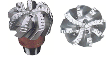
Hard formation drilling presents significant challenges to Polycrystalline Diamond Compact PDC bits. The major cause of reduced ROP and bit life has been identified as lateral downhole drill string vibration or ‘bit whirl’. The phenomenon manifests itself in the form of high irregular torques and poor rates of penetration. The negative impact of vibrations on PDC bits includes premature PDC failure and accelerated bit wear, which slows down the drilling rate and ultimately increases drilling costs.
What is Bit Whirl?
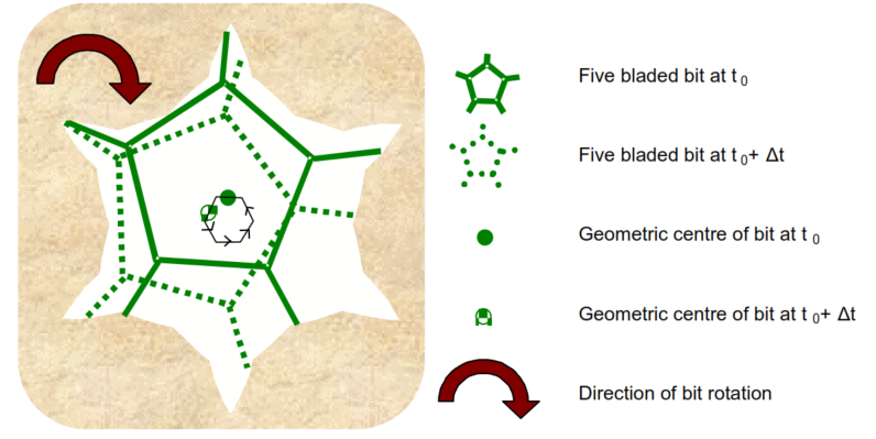
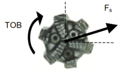
Bit whirl refers to the destructive backward whirling mode of the drilling bit. Backward whirling begins when some irregularity, like a change in formation or weight on bit, causes a frictional force between the drilling bit and the borehole wall. This force moves the instantaneous center of rotation away from the geometric center of the bit and towards the borehole wall. This process can continue and cause the bit to ‘walk’ around the hole. Figure 1 provides an example.
How Can The Effectiveness of Bit Whirl Be Increased?
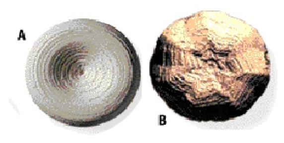
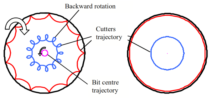
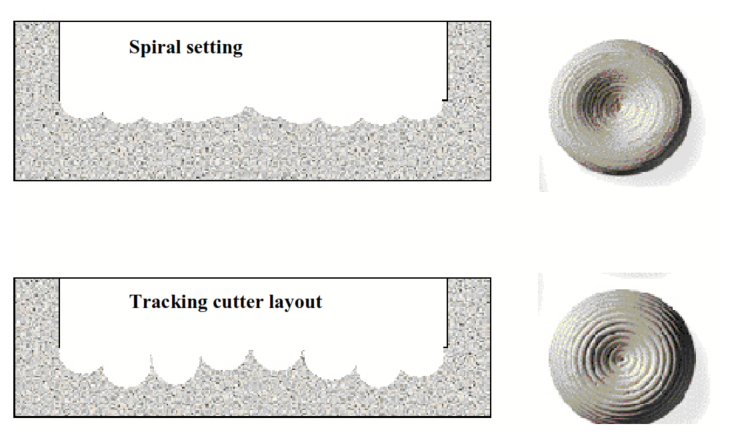
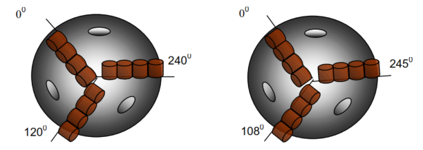
Figure 2 shows the impact of bit vibration on the bottom hole pattern. Figure 2AA displays a circular concentric trajectory of each cutter on a smooth drilling bit. In contrast, Figure 2B depicts a multi-lobed bottom-hole pattern that is typical for a whirling bit. Kinematical analysis of whirling bits has revealed that the number of blades on the bit is related to the number of bottom hole lobes. For instance, five-bladed bits in Figure 1 generate a 6, 11, 16, or similar lobed bottom hole pattern depending on their whirling mode.
RPM is Also A Factor
In drilling operations, the speed at which the drill bit spins is related to its tendency to whirl. For a five-bladed bit, the whirling speed can be several times faster than the drill string rotary speed. High whirling speeds can create strong centrifugal forces that increase the side loading on the bit, leading to an even stronger whirling tendency. Once the bit starts whirling, it can be difficult to stop, and the only solution is to stop the rotation and break in the bit at a low RPM and WOB.
This process is necessary to mill away the multi-lobed bottom hole pattern that causes the whirling motion. A whirling bit can cause cutters to move backward and sideways, which is different from a non-whirling bit. Due to the whirling motion, the diamond cutters are subjected to high-impact loads, which can cause the spalling of the diamond table and ultimately lead to premature cutter failure.
Off Center Rotations & Side Forces
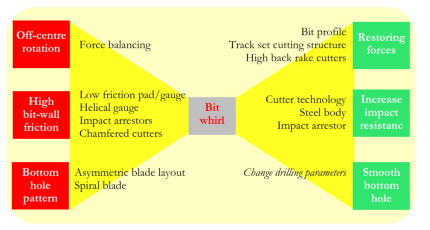
Bit whirl is favored by off-center rotation and high side forces when the bit contacts the borehole wall (high apparent friction coefficient) and generates a characteristic bottom hole pattern (Figure 2). Counteracting these three factors has been the purpose of strategies to reduce or eliminate bit vibrations and their effects.
Limit Off-Center Rotation Effect On Bit Whirl
Force Balancing
PDC cutters exert forces on the formation as the bit rotates and penetrates. These forces can be derived from laboratory cutter testing and used to create bit-force balance models. By calculating torque and side force (F), these models provide force balance during the design phase.
The force imbalance of PDC bits is defined as the ratio between the resultant side force and the weight-on-bit or
Force Imbalance = Fs/WOB x 100%
Force imbalance in PDC bits can cause lateral vibrations, so it’s crucial to design them with minimal force imbalance. This is difficult as the side force direction and magnitude depend on various factors.
Tracking Cutting Structure
To prevent bit whirl, tracking cutting structures are used. These create concentric ridges at the bottom of the hole, which help to push the rotation center back to the geometric center of the bit. The latest tracking cutter bits use different-sized cutting elements to stabilize without affecting ROP. The concept of track sets is also applied to groups of cutters to improve ROP and limit the exposure of cutters to impact loads.
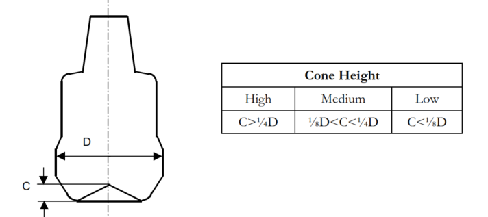
Bit Inner Profile
Cutters inside the cone of high cone bits provide an extra restoring force, resist lateral displacement effectively and rotate in the opposite direction to the cutters outside the cone, stabilizing the bit. However, commercially available deep-cone bits still rotate, especially at high speeds and should be avoided in formations with hard and soft interbedded layers.
Lower Apparent Gauge-Wall Coefficient Of Friction
Low Friction Gauge Pad Bits
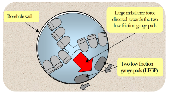
Normally, the force imbalance should be as small as possible. Some anti-whirl bits are deliberately equipped with an unbalanced cutting structure. In such a bit, the resultant side force is directed to pads with much lower frictional contact with the borehole wall than the gauge cutters (See Figure 32). Hence, the friction force is small, and the bit slides at the borehole wall instead of walking around the hole. Recent anti-whirl designs use low friction pads bridging two or more blades; this allows better angular coverage.
Indeed, from field experience, it has been shown that the tendency of a bit to whirl backward can be reduced by low-friction-gauge pad bits, leading to good drilling performance. However, Langeveld [14]] showed that the tendency to whirl backward returns above a critical bit speed depending on the actual hole size drilled and the weight on the bit applied. Hence, good control of the bit rotary speed and the applied weight-on-bit is required to take full advantage of the anti-whirl bit’s favorable dynamic characteristics. Liaison with the bit supplier is recommended.
LFGP bits drill a gauge hole; this may cause additional drag when pulling out of the hole.
Gauge Design Effect On Bit Whirl
Low friction gauge pads were developed to reduce the ability of the gauge to bite into the borehole wall and induce bit whirl. These gauge pads contain tungsten carbide or diamond inserts with a blunt surface. In addition, the wear elements and all corners and edges are rounded to help reduce the number of possible pivot points. The elimination of pivot points will reduce the whirl a bit.
The coverage of the gauge is also important. It is generally accepted that the more coverage there is, the more stable a bit becomes. Spiralled gauge section designs provide increased gauge coverage without reducing junk slot area. The load is passed more smoothly to the next blade, which, again, reduces pivoting and the tendency to whirl.
To achieve fully circumferential gauge contact, the spiral angle required is high. This is particularly true for bits with fewer blades and shorter gauge lengths. Consequently, the angled gauge pads can restrict the flow of cuttings from the bit face through the junk slots, compromising the hydraulic performance of the bit. A recent development is using full (3600) contact gauge rings. Field tests with these types of bits yielded positive results. However, the enclosed junk slots might reduce the hydraulic performance of the bit. This concept is used mainly in bi-center technology and for steerable bits.
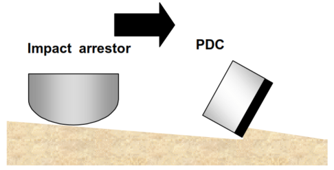
Impact Arrestors
The bit is typically positioned in the nose and gauge area. Impact arrestors are protrusions from the bit body aligned directly behind a PDC cutter. (See Figure 35) Impact arrestors are designed to prevent cutter damage caused by overloading due to string dynamics or a formation transition (soft to hard). In case of a shock or a formation transition, the impact arrestor takes most of the load, preventing excessive cutter loading. The impact arrestors, positioned in the gauge, control the depth of cut for the sole purpose of preventing wellbore enlargement and inhibiting whirl tendencies.
Initially the cutter protrudes concerning the arrestor. After some time, the cutter wear is no longer determined by the cutter but by the wear of the arrestor. This limits the depth of cut, which will hurt the penetration rate (ROP). Another disadvantage of impact arrestors is the extra torque generated by the arrestor. This extra torque reduces the efficiency of the drilling process.
Other Features To Control Bit Whirl
Asymmetric Blade Layout
Disrupting the angular regularity of a lobed bottom hole pattern can also combat bit whirl. The asymmetric cutter layout allows cutter blades (see Figure 36) to fit into a lobed bottom hole pattern in a regular, periodic manner, contributing to the bit whirl self-regeneration. An asymmetric blade layout interrupts the periodic vibration pattern and permits the bit to resist generation of the lobed patterns that are characteristic of ‘bit whirl’. Similarly, spiral blades do not allow the lobed pattern to develop.
Cutter Technology
In general, cutter technology primarily aims to make the cutters less vulnerable to bit whirl damage rather than trying to prevent bit whirl. However, some authors [19] state that less aggressive cutters (more back rake) would help to reduce the tendency of the whirl.
Advancements in cutter technology have been made through increasing diamond volume for greater abrasion resistance and significantly more impact resistance.
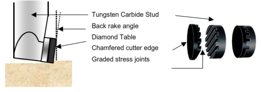
In addition, unique cutter geometries provide new means of stress dissipation: A grooved interface between the diamond table and the tungsten carbide stud creates what the diamond industry calls a ‘graded stress joint’. Figure 37 displays this graded stress joint as a parallel ridge. Other designs are used as well. The idea behind the graded stress joint is that due to the addition of a mixed intermediate layer, the residual stress caused by the difference in thermal expansion coefficients can be lowered, which mitigates the spalling tendency of the diamond table.
It has also been found that the cutter edge geometry is important concerning the initiation of the whirl and the tendency of cutters to chip. A sharp right-angle edge on a cutter creates a very aggressive cutting surface that increases the tendency for a bit to bite in the hole wall and start whirling. The sharp cutting edge is also much more prone to spalling of the diamond table. Repeated laboratory testing with bits with chamfered cutters demonstrated a very significant reduction of the number of spalled cutters [20]. However, by chamfering cutters the ROP will be negatively affected. Hence, the bit manufacturer has to find an optimum between reduced whirl tendency, less cutter damage and maximum ROP.
Application to Bi-Center Bit and Reamer Wings
Bi-center bits are PDC bits with eccentricities designed to drill a diameter larger than the previous casing ID. Bi-center bits are very sensitive to whirl. It has the same destructive effects as normal bits but also leads to under-gauge holes relative to the design diameter. Reducing the whirl tendency has been of vital importance to the development of bi-center bit technology. The reduction has been achieved by applying the previously described methods to bi-centre bits. Force balance and low friction pad techniques needed further extensions.
How Does Force Balancing Affect Bit Whirl?
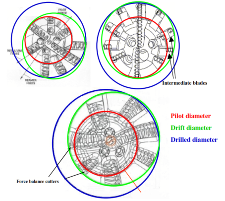
Force balancing of a bi-center bit is more difficult than for a standard PDC bit. Balancing the wing force with the pilot was not sufficient, the reamer force being larger than the pilot force. As a consequence, some additional features have been used. Shape cutters, i.e., cutters with very large chamfer, were used to generate additional lateral force on the pilot. The bit geometry also changed to help force balance; its evolution is shown in Figure 38. Intermediate blades (upright) increase diamond volume and help force balancing. The positioning of the pilot inside the reamer wing allows cutters to be placed opposite the three gauge blades.
Low Friction Blade
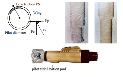
The low friction pad concept was applied to reamer wing stabilization (Figure 39) because the reamer wing is naturally unbalanced. A low-friction pilot stabilization pad is positioned below the reamer wing and balances its lateral force. The technique is only effective if the pilot hole is in gauge, which is not the case for all pilot holes.
References
- Bit Whirl—A New Theory of PDC Bit Failure, J. Ford Brett; Thomas M. Warron; Suzanne M. Bohr SPE Drill Eng 5 (04): 275–281. Paper Number: SPE-19571-PA
- Abdul Majeed, Fesmi. (2012). Drill Bit Whirl Mitigation Analysis: An Under Actuated System Perspective. International Journal of Sustainable Energy Development. 1.
- Drillstring Vibration Part 3b: Bit Whirl – YouTube, https://www.youtube.com/watch?v=rh0vcFAtenE