The system used for closing the BOP’s is a high-pressure hydraulic fluid accumulator unit. Hydraulic fluid is stored under pressure, the pressure being provided by stored nitrogen. When hydraulic oil is forced into the accumulator by a small volume, high-pressure pump, the nitrogen is compressed, storing potential energy. When the BOP’s are activated the pressured oil is released, either opening or closing the BOP’s. Hydraulic pumps replenish the accumulator with the same amount of fluid that was used to operate the BOP. The accumulator must also be equipped to allow varying pressures. When stripping pipe operations through an annular preventer, constant pressure must be maintained as the tool joints pass through the packing element. Accumulators commonly have minimum working pressures of 1200 psi and maximum working pressures of between 1500 and 3000 psi.
General Types of BOP Accumulators
Accumulators are ASME-coded pressure vessels for the storage of high-pressure fluid. These accumulators as a part of the BOP control unit are available in a variety of sizes, types, capacities, and pressure ratings. The two (2) basic types are bladder and float which are available in cylindrical or ball styles. The accumulators can either be bottom or top loading. Top loading means the bladder or float can be removed from the top while it is still mounted on the accumulator unit. Bottom loading accumulators must be removed from the accumulator unit to be serviced. Bladder and buoyant float-type accumulators can be repaired in the field without destroying their stamp of approval.
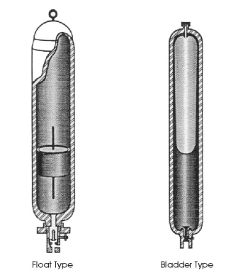
The bladder type accumulator retains a rubber bladder that separates the nitrogen from the stored hydraulic fluid. The gas is injected into the bladder through the precharge valve at the top of the bottle and the hydraulic fluid penetrates the accumulator at the bottom. A poppet valve at the base of the bottle prevents extrusion and damage to the bladder once all the hydraulic fluid has been discharged.
In the float type BOP accumulator, the gas is introduced at the top of the bottle and is kept separate from the stored fluid by a buoyant float. The escape of the gas through the fluid port at the base of the bottle is contained by the weight of the float actuating a shut-off valve once all the fluid has been ejected.
General Requirement
Accumulator bottles are containers that store hydraulic fluid under pressure for use in effecting blowout preventer closure. Through the use of compressed nitrogen gas, these containers store energy which can be used to effect rapid preventer closure. There are two types of BOP accumulator bottles in common usage, separator and float types. The separator type uses a flexible diaphragm to effect positive separation of the nitrogen gas from the hydraulic fluid. The float type utilizes a floating piston to affect the separation of the nitrogen gas from the hydraulic fluid.
BOP Accumulator Unit Volumetric Capacity
- As a minimum requirement, all blowout preventer control units should be equipped with accumulator bottles with sufficient volumetric capacity to provide the usable fluid volume (with pumps inoperative) to close one pipe BOP ram and the annular preventer in the stack plus the volume to open the hydraulic choke line valve.
- Usable fluid volume is defined as the volume of fluid recoverable from an accumulator between the accumulator operating pressure and 200 psi above the precharge pressure. The accumulator operating pressure is the pressure to which accumulators are charged with hydraulic fluid.
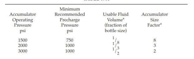
- The minimum recommended accumulator volume (nitrogen plus fluid) should be determined by multiplying the accumulator size factor (refer to Table 8-A) times the calculated volume to close the annular preventer and one pipe ram plus the volume to open the hydraulic choke line valve.
Response Time For The BOP Accumulator Unit
The closing system should be capable of closing each ram preventer within 30 seconds. Closing time should not exceed 30 seconds for annular preventers smaller than 18 3/4 inches and 45 seconds for annular preventers 18 3/4 inches and larger.
Operating Pressure and Precharge Requirements for Accumulators
- No accumulator bottle should be operated at a pressure greater than its rated working pressure.
- The precharge pressure on each accumulator bottle should be measured during the initial closing unit installation on each well and adjusted if necessary (refer to Para. 8.A.4). Only nitrogen gas should be used for accumulator precharge. The precharge pressure should be checked frequently during well drilling operations.
Requirements for BOP Accumulator Unit Valves, Fittings, and Pressure Gauges
- Multi-bottle accumulator banks should have valving for bank isolation. An isolation valve should have a rated working pressure at least equivalent to the designed working pressure of the system to which it is attached and must be in the open position except when accumulators are isolated for servicing, testing, or transporting. Accumulator bottles may be installed in banks of approximately 160 gallons capacity if desired, but with a minimum of two banks.
- The necessary valves and fittings should be provided on each accumulator bank to allow a pressure gauge to be readily attached without having to remove all accumulator banks from service. An accurate pressure gauge for measuring the accumulator precharge pressure should be readily available for installation at any time.
BOP Accumulator Location
The accumulator shall be located at a remote location, at least 60 feet distance from the wellbore for oil wells and 100 feet for gas wells, shielded from the wellhead and protected from other operations around the rig. There must be at least two (2) sets of remote controls for operating the accumulator to activate the BOPs. One remote control shall be on the rig floor, accessible to and visible by the driller and the other shall be located 100’ from the wellhead and near the Company Representative’s office (drilling engineer). Master Controls shall be at the accumulator.
Pump System
The primary electric/hydraulic pump system and the secondary air/hydraulic pump system must be independent of each other and fully operational when the BOP accumulator is in use. The high-pressure set point for both the electric pump and air pump should be 3,000 psi. The low-pressure setpoint should be above 2,800 psi for both systems. Do not bleed off pressure due to ambient temperature rise. Pressure may vary from 3,000 to 3,400 psi in a 24-hour period.
Pressure Regulator Settings
It is preferred that the pressure regulators for the annular preventer and ram preventers will be set as per the manufacturer’s specification/recommendation.
Accumulator Sizing
It is important to determine the total BOP accumulator capacity while designing the BOP control unit. The particular criteria to be applied relies on the related operating oil and gas company instructions. At the same time, you can consider the following:
The accumulators shall be able to support all the BOP functions and still have a pressure of 200 psi above the precharge pressure.
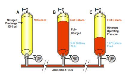
The operating pressure of accumulators is generally 3000 psi. A minimum of about 1200 psi is needed to maintain some annular preventers closed and so this is taken to be the minimum allowable pressure that should stay in the accumulator after operating the BOP functions. A precharge pressure of 1000 psi will therefore ensure that a small liquid reserve will remain in the bottles when the pressure in the system falls to 1200 psi. The figure below illustrates such situations for a BOP bladder-type accumulator.
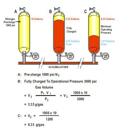
- Volume of hydraulic fluid at 3,000 psi equals 6.67 gallons.
- Volume of hydraulic fluid at 1,200 psi equals 1.67 gallons.
- Usable fluid operating under the above pressure; equals 6.67 – 1.67 = 5 gallons
- Let’s assume that all the fluids volume required for BOP function as per IADC equal 250 gallons.
- So the total number of bottles required equal 250 / 5 which equal 50 bottles
With the help of these pressures, we can calculate the amount of usable fluid and determine the total volume of fluid & the number of bottles that is required by the various stack functions. The calculations are different however for surface and subsea accumulators.
In subsea accumulators, we shall add seawater hydrostatic pressure to the initial gas pre-charge pressure of 1000 psi (subsea bottles), this will lower the total useable fluid volumes.
This seawater hydrostatic increase on the stack-mounted bottles is to overcome any hydrostatic compression on the hose bundles prior to entering the pods.
Accumulator Inspections Recommendations
Inspect BOP accumulator precharge every six months, at each rig move (BOP Control Unit Acceptance Procedures), or when a problem is suspected, whichever occurs first.
Note: Install a repair kit in each accumulator every three years.
IADC Recommendations
Defective Valves Check
Use the following procedure on each accumulator to determine if any of the accumulators have defective valve assemblies that are not closing completely or are leaking nitrogen.
- Turn off all pumps.
- Close the isolation valves on all accumulators except the one to be tested.
Note: It may be necessary to drain fluid from the reservoir before relieving accumulator pressure.
- Relieve the pressure in the BOP accumulator being tested to zero psi with the bleeder valve on the accumulator return line, and listen for a bubbling sound.
- If no bubbling sound is heard in the reservoir after the pressure is relieved, the accumulator valve assembly is working correctly. Repeat steps (1) through (4) for each accumulator and proceed to step 7b.
- If a bubbling sound is heard in the reservoir after the pressure is relieved, the accumulator valve assembly is not closing completely or is leaking nitrogen. Repair the valve assembly accord ing to the following instructions:
- Relieve the nitrogen precharge pressure in the accumulator with the nitrogen needle valve on the valve assembly.
- Remove the valve assembly, and repair it. See the Maintenance Procedures for repair instructions.
- Precharge the accumulator. See the Maintenance Procedures for precharge instruc tions.
- Close the bleeder valve on the accumulator return line.
- Repeat step 7A for each accumulator before continuing to step 7B.
Insufficient Precharge pressure
Determine if any of the accumulators do not have sufficient precharge pressure with the following procedure:
Note: This procedure will not determine if any of the accumulators have submerged floats.
- Ensure that all pumps are turned off.
- Ensure that The bleeder valve on the accumulator return line is closed.
- Ensure that the accumulator pressure gauge registers zero psi.
- Turn on the pumps. Wait 4 to 5 seconds for electric pumps, slightly longer (until the pump reaches a steady level of operation) for air pumps.
- Observe the accumulator pressure gauge.
- If the accumulator pressure gauge registers from 900 psi to 1100 psi, all accumulators have sufficient precharge pressure.
- If the accumulator pressure gauge registers below 900 psi, one or more accumulators has insufficient precharge pressure. Continue to step 7C.
Submerged Float
Perform the following tests on each BOP accumulator to determine which accumulator(s) has insufficient precharge pressure or a submerged float:
- Close the isolation valves on all accumulators except the one to be tested.
- Close the bleeder valve on the accumulator return line.
- Ensure that the accumulator pressure gauge registers zero psi.
- Turn on the pumps. Wait 4 to 5 seconds for electric pumps, slightly longer (until the pump reaches a steady level of operation) for air pumps.
- Observe the accumulator pressure gauge.
- If the accumulator pressure gauge registers from 900 to 1100 psi, the accumulator has sufficient precharge pressure.
- If the accumulator pressure gauge registers below 900 psi, the accumulator does not have sufficient precharge pressure. See the Maintenance Procedures for precharge instructions.
- If the accumulator pressure gauge registers a steady pressure increase from zero psi to 3000 psi, the float is submerged.
Note: As an option, to verify the accumulator precharge pressure, install a test gauge in the nitrogen needle valve on the accumulator valve assembly.
- Repeat step the above steps for each accumulator.
References:
- Well Control For Rig Site Drilling Team
- IADC Well Control MAnual