A Blowout Preventer (BOP) Control System as one of the drilling rig components, is a high-pressure hydraulic power unit fitted with directional control valves to safely control well kicks and prevent blowouts during drilling operations. A typical system offers a wide variety of equipment to meet the customer’s specific operational and economic criteria. The following text gives a brief description of the equipment and some of its major components.
Control systems for surface-mounted BOP blowout preventers used for well drilling are usually “closed-loop” design hydraulic systems. This means two lines are required for all pressure open/pressure close BOP stack functions, and that fluid in one line is returned to the control unit reservoir when the other line is pressurized. These systems lend themselves to the use of petroleum-based fluids for the control system operating fluid. Since there is a possibility of an “ecological incident” in the event of a system leak, many offshore drilling contractors are turning to the use of water-based control system fluids. Water-based fluids have no detrimental effect on operations as long as:
- The environmentally safe lubricating agent is added to the water.
- Freeze protection is provided if the system is to be operated in cold climates.
- The fluid is regularly inspected and bacteria growth is checked either by addition of chemical agents or timely replacement of the fluid.
Water base control system fluid can be premixed in proper ratios in accordance with the control system manufacturers’ recommendations. The control system manufacturer should specify control system fluid that is compatible with the equipment seals and materials.
Typical Surface BOP Control System
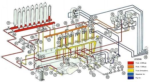
NOTE: System designed to meet API RP 16E must have Electric Remote Control Panels if they are used on offshore rigs.
- CUSTOMER AIR SUPPLY: Normal air supply is at 125 psi. Higher air pressure may require an air regulator for No. 88860 air pumps.
- AIR LUBRICATOR: Located on the air inlet line to the air-operated pumps. Use SAE 10 lubricating oil.
- BYPASS VALVE: To automatic hydro-pneumatic pressure switch. When pressures higher than the normal 3,000 psi are required, open this valve. Keep closed at all other times.
- AUTOMATIC HYDRO-PNEUMATIC PRESSURE SWITCH: The pressure switch is set at 2,900 psi cut-out when air and electric pumps are used. Otherwise set at 3,000 psi for air pumps alone. Adjustable spring tension control.
- AIR SHUT-OFF VALVES: Manually operated — to open or close the air supply to the air-operated hydraulic pumpS.
- AIR OPERATED HYDRAULIC PUMPS: Normal operating air pressure is 125 psi, (For No, 88550 pumps, maximum air pressure is 200 psi and for No. 88660 pumps maximum air pressure is 125 psi.)
- SUCTION SHUT-OFF VALVE: Manually operated. Keep normally open. One for each air-operated hydraulic pump suction line.
- SUCTION STRAINER: One for each air-operated hydraulic pump suction line. Has removable screens. for the best performance of the BOP control system, it should be cleaned every 30 days.
- CHECK VALVE: One for each air-operated hydraulic pump delivery line.
- ELECTRIC MOTOR-DRIVEN TRIPLEX OR DUPLEX PUMP ASSEMBLY.
- AUTOMATIC HYDRO-ELECTRIC PRESSURE SWITCH: The pressure switch is set at a 3,000 psi cut-out and 250 psi cut-in differential. Adjustable.
- ELECTRIC MOTOR STARTER (AUTOMATIC): Automatically starts or stops the electric motor driving the triplex or duplex pump. Works in conjunction with the automatic hydro-electric pressure switch and has a manual overriding on-off switch.
- SUCTION SHUT-OFF VALVE: Manually operated, normally open, Located in the suction line of the triplex pump.
- SUCTION STRAINER: Located in the suction line of the triplex or duplex pump,
- CHECK VALVE: Located in the delivery line of the triplex or duplex pump.
- ACCUMULATOR SHUT-OFF VALVE: Manually operated. Normally in the open position when the unit is in operation. Close when testing or skidding rig or when applying pressure over 3,000 psi to open the side of ram preventers, OPEN WHEN TEST IS COMPLETED.
- ACCUMULATORS OF BOP CONTROL SYSTEM: Check nitrogen precharge in BOP accumulator system every 30 days, Nitrogen precharge should be 1000 psi +/- 10% CAUTION: Use NITROGEN when adding to precharge. Other gases and air may cause fire and/or explosion,
- ACCUMULATOR RELIEF VALVE: Valve set to relieve at 3,500 psi.
- FLUID STRAINER: Located on the inlet side gl the pressure reducing and regulating valves. Clean the strainer every 30 days.
- PRESSURE REDUCING AND REGULATING VALVE: Manually operated. Adjust to the required continuous operating pressure of ram-type BOP’s.
- MAIN VALVE HEADER: 5000 psi W.P., 2″ all welded.
- 4-WAY VALVES: With air cylinder operators for remote operation from the control panels. Keep in the standard operating mode (open or close), NEVER IN CENTER POSITION.
- BYPASS VALVE: With air cylinder operator for remote operation from the control panels. In the CLOSE position, it puts regulated pressure on the main valve header (21), and in the OPEN Position, it puts full pump pressure on that header. Keep in a CLOSE position unless 3000 psi (or more) is required on ram-type BOPs.
- MANIFOLD RELIEF VALVE: Valve set to relieve at 5,500 psi.
- HYDRAULIC BLEEDER VALVE: Manually operated-normally closed, NOTE: This valve should be kept OPEN when pre-charging the accumulator bottles.
- PANEL-UNIT SELECTOR: Manual 3-way valve. Used in the BOP control system to apply pilot air pressure to the air-operated pressure-reducing and regulating valve, either from the air regulator on the unit or from the air regulator on the remote control panel
- PRESSURE REDUCING AND REGULATING VALVE — AIR OPERATED: Reduces the accumulator pressure to the required annular BOP operating pressure. Pressure can be varied tar stripping operations. Maxi- mum recommended operating pressure ut the annular preventer should not be exceeded.
- ACCUMULATOR PRESSURE GAUGE.
- MANIFOLD PRESSURE GAUGE.
- ANNULAR PREVENTER PRESSURE GAUGE.
- PNEUMATIC PRESSURE TRANSMITTER FOR ACCUMULATOR PRESSURE.
- PNEUMATIC PRESSURE TRANSMITTER FOR MANIFOLD PRESSURE,
- PNEUMATIC PRESSURE TRANSMITTER FOR ANNULAR PREVENTER PRESSURE,
- AIR FILTER: Located on the BOP control unit supply line to the air regulators.
- AIR REGULATOR FOR PRESSURE REDUCING AND REGULATING VALVE — AIR OPERATED,
- AIR REGULATOR FOR PNEUMATIC TRANSMITTER (33) FOR ANNULAR PRESSURE.
- AIR REGULATOR FOR PNEUMATIC PRESSURE TRANSMITTER (31) FOR ANNULAR PRESSURE.
- AIR REGULATOR FOR PNEUMATIC PRESSURE TRANSMITTER (32) FOR MANIFOLD PRES- SURE. NOTE: Air regulator controls for pneumatic transmitters are normally set at 15 psi. Increase or decrease air pressure to calibrate the panel gauge to the hydraulic pressure gauge on the unit.
- AIR JUNCTION BOX: To connect the air-lines on the unit to the air-lines coming from the remote control panels through an air cable.
- RIG TEST CHECK VALVE.
- HYDRAULIC FLUID FILL PORT.
- INSPECTION PLUG PORT.
- RIG TEST OUTLET ISOLATOR VALVE: High pressure, manually operated. Close when rig testing — open when the test is complete.
- RIG TEST RELIEF VALVE: Valve set to relieve at 6500 psi.
- RIG TEST PRESSURE GAUGE.
- 46A. RIG SKID OUTLET and 46B. VALVE HEADER ISOLATOR VALVES: Manually operated. Close the valve header isolator valve and open the rig skid isolator valve when the rig skidding. Open the valve header isolator valve and close the rig skid isolator valve during normal drilling operations.
- RIG SKID RELIEF VALVE: Valve set to relieve at 2500 psi.
- RIG SKID PRESSURE GAUGE.
- ACCUMULATOR BANK ISOLATOR VALVES: Manually operated, normally open.
- RIG SKID RETURN. Customer’s connection.
- RIG SKID OUTLET. Customer’s connection.
- ELECTRIC POWER. Customer’s connection.
- RIG TEST OUTLET. Customer’s connection.
BOP Control System Installation
The main accumulator with its hydraulic control manifold, separate hydraulic manifold, or hydraulic panel should be installed in a safe area protected from falling debris or gas accumulations during a blowout. All of the control functions should be operable from the drill floor by use of a remote control panel. A second remote control panel is recommended. This panel is normally located in the tool pushers‘ office or in a safe egress area and is intended as a last means to close in the well as the rig is being abandoned. The initial installation, (and each time the rig is moved), should be fully tested according to the recommended BOP control system acceptance procedures to ensure proper leak-free operation and correctness of function.
The hydrostatic test should be to full working pressure and/or ten percent below any relief valves in the line. Piping downstream of the pressure-reducing and regulating valves should be tested to the maximum (full open) regulator settings. Automatic pump system cut-off devices should be tested to ensure the pump(s) cut off at the maximum system design working pressure.
The system design capacities should be verified at the initial installation and interface of the control system to the BOP stack. The contractor must ensure that all oil and gas companies, local statutes, governmental, and other governing agencies at the drilling venue have been met in the design. In particular, the contractor must ensure the following:
- The control system design meets or exceeds the performance requirements of the most stringent of the regulatory bodies in force.
- Accumulator precharge is maintained within the control system manufacturer’s specification.
- Pump system cut “on” and cut-off automatic set points are maintained at the control system manufacturer’s specification for the system design.
- Closing response times from activation at any control point are within the time limits of the most stringent of the regulatory bodies in force.
NOTE: The minimum performance and capacity recommendations for surface BOP well-drilling control systems are listed in API RP 16E, Section 16E.2. Refer to the latest edition.
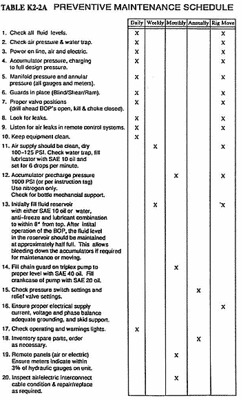
Typical Maintenance Items
While BOP control systems by various manufacturers may vary widely in color, size, configuration, and layout, they are functionally very similar. Figure 1 “Typical Surface BOP Control System” and table 2 “Preventative Maintenance Schedule Check List” are not intended to promote any manufacturer’s product. They are intended to highlight areas that need to be identified and properly maintained to ensure the capability or the control system to perform to its design intent.
Operational Recommendations
Well control procedures are previously discussed. These procedures are intended to inform of possible well control practices that have proven practical. They should not be interpreted to be a solution to all problems. BOP Control system manufacturers generally make the following operational recommendations.
- During normal drilling, the blowout preventer control valves are typically in the “open” position, and kill & choke valves are typically in the “closed” position. This will hydraulically lock the BOP in position, give a visual indication of the annular BOP, ram, or valve position, and most importantly, indicate leaks in the valves, lines or BOP which can be detected by the pumps coming on too frequently.
- Ensure all pump system (air and electric) power is “online” at all times.
- Ensure all accumulator banks are “on time” at all times.
- Ensure pump system automatic “on”/”off” limits are properly set. Setting the pump system cut off too low results in significantly reducing the usable fluid capacity of the accumulator system. Setting the pump system “on” point too low results in accumulator pressure being too low, and the usable fluid capacity is reduced significantly so that the BOP performance is adversely affected.
- Ensure the BOP control system nitrogen precharge in all of the accumulators is properly maintained within the specified limits. Reduced precharge decreases the recoverable (usable) fluid from the accumulator. Zero precharge (probably ruptured bladder) equals nil recoverable fluid. The nitrogen precharge must be measured when there is zero hydraulic pressure on the accumulators. This means they must be bled back to the reservoir to measure precharge.
- Operate with the fluid reservoir approximately half full. Reservoirs are typically sized to hold at least twice the recoverable (usable) fluid of the accumulator system. This means bleeding down all of the accumulators is possible without overflowing the reservoir. Newer systems built in accordance with API RP 16E have twenty-five percent (25%) accumulator bank isolation. They also have isolation and bleed valves on each bank permitting checking precharge on one bank at a time without shutting down operations.
- Ensure all components of the BOP control system are in proper working order, clean, and, where required, lubricated.
Nitrogen Back-up System Operation
Nitrogen backup can, implemented successfully, fill this void if the rig stored air system is not designed to handle it (used for closing blowout preventers in the event hydraulic capability is lost)
The nitrogen backup system of the BOP control system should include pressure regulation, relief valve protection, and either automatic intervention in the event rig air pressure is interrupted, or be selectively available from the driller’s panel and at least one “safe area” remote panel.
- Set Annular Regulator to the highest regulated pressure.
- Place Manifold Regulator Bypass Valve in the “HIGH” position.
- Ensure Nitrogen Bottle Valves are open and place the Nitrogen System Isolator Valve in the “OPEN” position.
- Close appropriate BOPs for Well Control situations. NOTE: Leave BOPs closed until they can be opened hydraulically, (Refer to the following steps).
- Remove four (4) inch tank inspection plugs at the top end of the Reservoir.
- Close the Nitrogen Isolator Valve (after the emergency). With BOPs still closed, open the Manifold Bleed Valve and slowly bleed Nitrogen back to the Reservoir.
- If Nitrogen was used to close the Annular, slowly decrease the Annular Regulator setting allowing Nitrogen to bleed back to the Reservoir.
- Re-establish hydraulic pressure and return the Manifold Regulator Bypass to the “LOW” position.
- Reset the Annular Regulator to the correct operating pressure.
- Open the BOPs hydraulically.