The term “coiled tubing” means a set of durable CT strings (CGT), a complex of surface equipment, consisting of the coiled tubing unit itself (providing tripping of the CT string – Tripping pipe procedures), and a complex of equipment, including a mud pump, compressors for injecting inert gas or a booster unit, a generator inert gas, process fluid heater, wellhead choke device and wellhead equipment, including, in particular, blowout preventer. Downhole equipment may include various nozzles, rock breaking tools, packers (permanent packers), cutting tools, deflectors, and downhole motors. The instrumentation includes equipment for logging, well surveys, inclinometer.
The main Coiled Tubing Surface Equipment is:
- Primary Equipment
- Pressure / Well Control Equipment (for more detail see Coiled Tubing BOP article)
- Stuffing Box
- Quad Blowout Preventers (BOP)
- Shear Seal BOP
- Annular BOP (optional)
- Auxiliary Surface Equipment
Coiled Tubing Surface Equipment Mechanism
- The rigging vertically above the well contains several barrier elements. There is usually a BOP installed closest to the well. This is hydraulically operated with BOP accumulator support in case of failure of the hydraulics.
- A lubricator is fitted between the BOP and the strippers, which are pipes that are screwed together and pressure tested. In the lubricator, there is a quick coupling that can be opened to insert and remove the tool string.
- Two independent barriers ( strippers ) are mounted above the lubricator. One acts as an active barrier element as long as there are pipes in the well, and the other is a backup barrier. The injector is mounted above the strippers. It is the driving force that pushes the coiled tubing into the well and pulls it out again.
- The gooseneck is mounted on top of the injector. It should guide the coiled tubing into the injector without exposing the coiled tubing to large bending forces.
- The coiled tubing comes from a drum where it is wound in and out by means of a guide arm. In the drum, the coiled tubing is connected to the core, so that fluid can be pumped in from the outside to the inside of the coiled tubing.
- Behind the coiled tubing is the control unit, where the operator sits and controls the coiled tubing operation.
- To drive the drum, injector, and barriers, there is a separate hydraulic ” power unit” (HPU) that is connected with hydraulic hoses to each component.
Coiled Tubing Reel Unit Surface Equipment
Coiled tubing itself is kept on large reels (as the flexible wireline cable). The reel is kept on an axle and is also rotated using a motor (hydraulic) through a chain drive. The core diameter varies with the dimension of the pipe; the larger the pipe dimension pipe, the larger the core diameter.
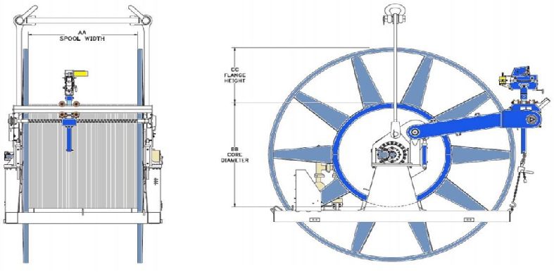
This drive system has two functions:
- When coiling, this drive system rotates the reel so as to coil the tubing under constant tension.
- When uncoiling tubing, i.e. running into the hole, the motor works as a constant-torque brake, thus maintaining the tubing to the gooseneck under tension.
The coiled tubing reel drive system itself is not utilized to lower or hoist tubing in the well, which is the purpose of the injector head.
It is desirable to have a pipe length adapted to the task so that the pump friction through the coiled tubing is as small as possible. The drums can be delivered with lengths of up to 10,000 meters of pipe.
The drum must also have a braking system that automatically brakes the drum if the equipment’s hydraulics fails.
Read the full article on Coiled Tubing Reel Unit
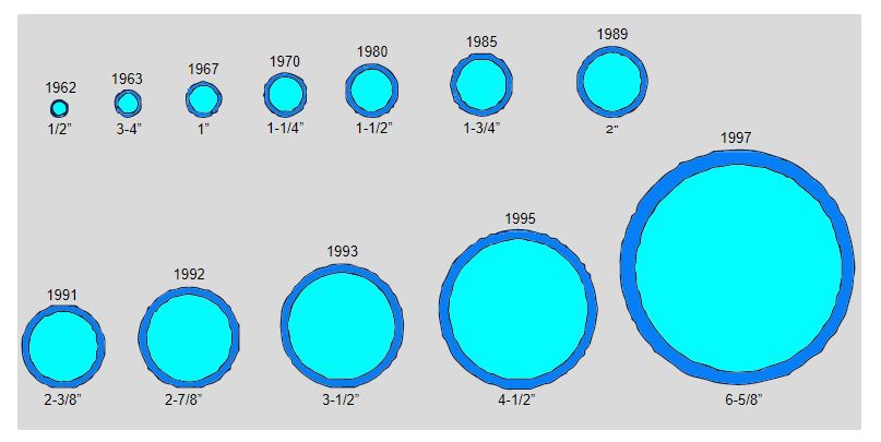
The Coiled Tubing
Coiled tubes are produced in many different dimensions and material qualities, depending on which well conditions they are to suit. In wells with H2S and CO2, the steel must have an alloy that prevents it from becoming brittle. In other cases, large volumes must be pumped. Then a coil with a larger ID must be used.
The largest dimensions are only used for special assignments or as production pipes.
The coiled tubing is exposed to wear both inside and outside. Inside, chemicals and solids (sand particles) affect the surface, so the pipe’s wall thickness can become thinner. Externally, the bending of the coiled tubing will weaken the tube when it is driven in and out of the drum, over the gooseneck, and into the injector. Pushing and pulling forces through the stripper and injector also load the pipe.
The pipe is inspected regularly. The outer diameter is then measured to check whether the material has become thinner and the pipe has been deformed into an oval shape. At the same time, the surface is checked for erosion and corrosion damage.
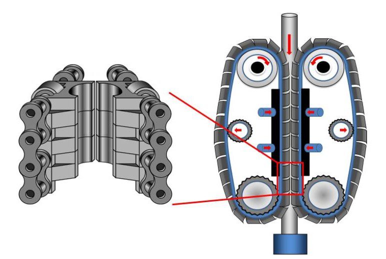
Injector Head
The coiled tubing is pushed into the well with an injector. The injector equipment consists of the motors, chains, and gripper blocks that drive the coiled tubing back and forth in the well.
Two hydraulically operated motors rotate in opposite directions relative to each other so that they guide the chains in the same direction. There is also a gearbox that changes the direction of the engines and distributes the torque and speed of the engines.
On each of the motors, a chain also goes around two gears to form a circular motion. The chains are driven by the motors to move the coiled tubing up or down the well.
- It simply holds the coiled tubing using profiled gripper blocks & hydraulically driven chains. Hydraulic tensioning instruments can maintain correct tension on the drive chains to prevent crushing or slippage of the tubing.
- The injector head is required to transfer the force necessary to inject, retract or hold the tubing with accuracy control while running in or pulling out the hole.
- In addition, the hydraulic drive motors are equipped with brakes that will hold the tubing should the hydraulics fail.
Read the full article on Coiled Tubing Injector Head.
The Grip Blocks
Grip blocks are mounted on the chains, which have a C shape so that they fit on half of the outer diameter of the coiled tubing. Where the chains meet in the center of the injector, the gripper blocks are clamped against the coiled tubing and pushed in the direction in which the motor drives it. The gripper blocks are easily clamped on the chain and can be replaced to other dimensions or replaced if they become worn.
In order for the gripping blocks to hold tightly around the coiled tubing, the two chains are pressed against each other by a hydraulically operated plate ( skate ) which lies behind each of the chains. The plate is located behind several joints with gripping blocks so that a larger gripping surface is provided against the coiled tubing and hydraulic clamping force on the gripping blocks.
The Gooseneck
At the top of the injector, there is a curved guide frame that is used to guide the pipe from the drum into the injector. The guide frame is called a gooseneck.
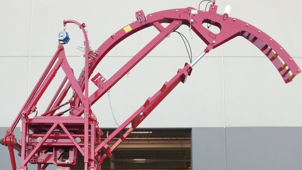
The gooseneck should give the coiled tubing a fine arc towards the well, so that the coiled tubing is not bent over the yield strength of the steel which is a must to be avoided, as it can damage the pipe and cause crack and leak.
The radius of the gooseneck must be at least 48 times the diameter of the coiled tubing. 1 ½ ”coiled tubing uses a gooseneck with a radius of 1.8 meters.
The angle of the arc may change slightly depending on how high or low the drum is placed. It can be done mechanically or hydraulically.
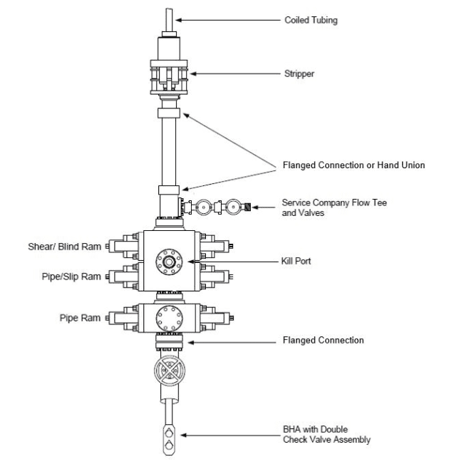
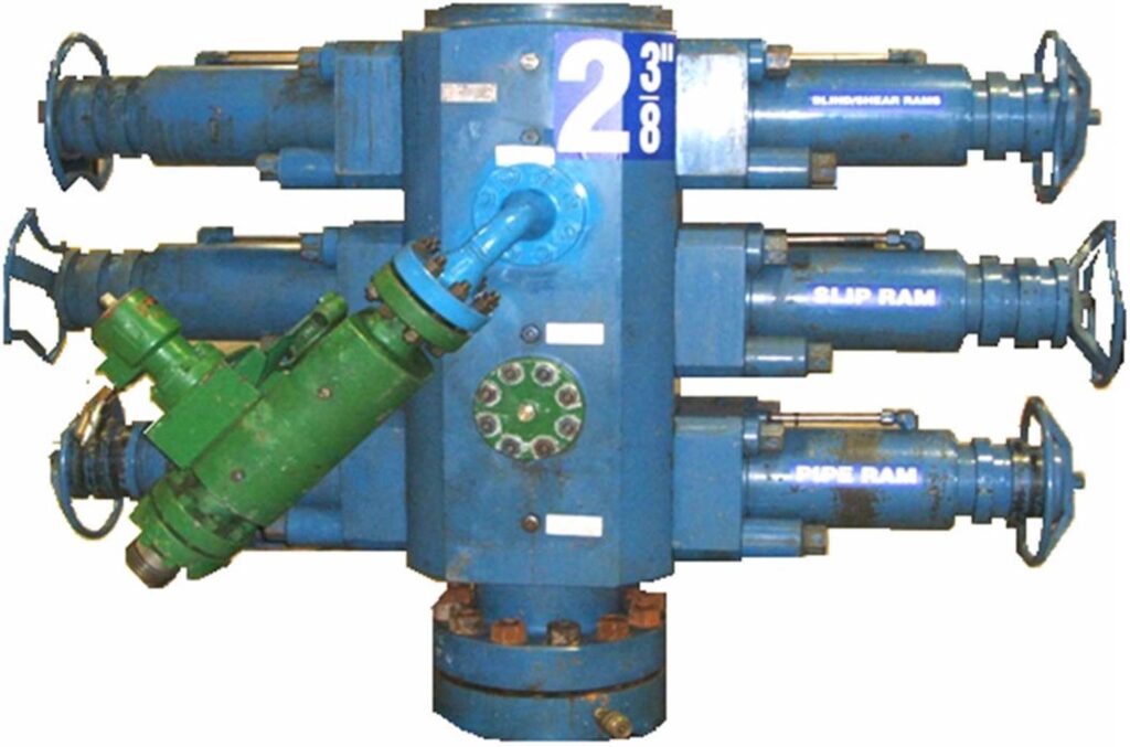
Pressure Control Surface Equipment For Coiled Tubing
When CT is rigged on a completed well, the barrier elements are built on top of each other. At the top are two stripper boxes that are active barriers (dynamic) during well intervention. Below is the coiled tubing BOP. The BOP is used if the stripper is leaking and needs to be maintained, when the well is closed, or when the coiled tubing is to be hung off or cut.
CT BOP is built in the same way as a drilling BOP, but is significantly smaller in dimension, up to 7 1/16 ”ID.
Read the full article on Coiled Tubing BOP & Pressure control Equipment
Safety Head
A safety head in coiled tubing is a shearing and closing device equipment that is mounted on top of the well (valve tree). It can cut both the coiled tubing and the tool string as needed. In addition, it can seal against the well when closed.
Lubricator
The lubricator consists of several pipes that are mounted together as a pipe extension of the well. It is used to insert and remove the tool string to be connected to the coiled tubing equipment. The lubricator must stand over two barriers in the well. The length is determined by how long the tool string is to be used.
The lubricator is mounted above the safety head on the valve tree on dry wells, or on top of the Workover riser for subsea-mounted wells. If it is necessary to build height through several tires, drilling riser pipes can be fitted over the valve tree under the lubricator. CT BOP is mounted under the lubricator.
The lubricator is opened and closed with a hydraulic quick union that is pressure approved for use on any living well. When the lubricator is to be opened, valves to the well under the lubricator must be closed and the internal pressure released before the quick coupling can be released.
When the lubricator is fixed together, this is part of the surface equipment where the well pressure will reach the stripper elements. The lubricator must therefore be leak tested together with the rest of the surface coiled tubing equipment. Fluid is filled into the surface equipment via coupling in the lubricator. This injection point is also connected to a pressure test pump when the surface equipment is leak tested.
Power Pack & Control Cabin
Hydraulic power is required to be supplied to the injector, drum, BOP, and strippers. The power is generated by means of diesel engines that are inserted in an approved container. The container also has a hydraulic tank, cooling for the diesel engine, hoses, and control panel.
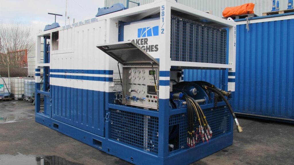
- Most coiled tubing units use a diesel engine as the power source for the hydraulic pumps, which in turn move the hydraulic motors in all components of coiled tubing.
- The control cabin is sited to provide a clear view of the wellhead, injector head and the tubing reel. It houses all the controls relevant to the operation
Read the full article on Power Pack & Control Cabin
Auxiliary Surface Equipment For Coiled Tubing
Some examples of Auxiliary Surface Equipment are as follows:
Weight Indicator
The two principle weight indicator systems include:
- Mechanical: The mechanical type is a side-mounted load cell that works on the principle of transference of hydraulic pressure.
- Electrical: The electrical type is a strain gauge load cell that may either be centrally or side-mounted onto the injector head.
The main check to be carried out before running in the hole is to ensure that the weight indicator is reading accurately. Once the injector head, complete with the gooseneck and coiled tubing stabbed on, is lifted onto the wellhead a check on the weight indicator can be made. When the injector head is completely tied back and ready for operations, prior to the well being opened up, the weight indicator should read the weight of the tool string only. The amount of coiled tubing in the well is minimal at this stage and will not affect the weight reading. If the reading is not correct at this point the error should be noted so that allowances can be made during the operation (plus allowances for friction).
CT Reel Connectors
Coiled Tubing Collector (Slip Ring Joint)
During stiff wireline operations, it is necessary to provide a means of communication from the wireline, which is turning with the CT reel, to a fixed point. This is accomplished using a slip ring joint (collector) fixed to the side of the CT reel. The collector consists of a series of brushes that rotate with the reel whilst maintaining contact with a stationary conducting ring. Connections from this ring are wired to a brass plug on the collector body, which enables direct communication from the BHA to the surface logging equipment.
Hydraulic Quick Connector (HQC)
Installed between the coiled tubing BOP and the stuffing box or riser, the HQC provides a safe and easy method of injector rig-up.
Using standard connection unions with the larger coiled tubing sizes can sometimes result in the injector hanging off-plumb, making stabbing unusually difficult. The HQC has been designed to allow stabbing of the injector with a 10° offset, as the standard HQC has an integral guide to aid the alignment of the mating connections.
The HQC has a mechanical latch mechanism that when fully connected provides positive engagement on the locking dogs, as well as actuating an external indicator that shows whether the equipment is correctly “stabbed” on. It is released by applying hydraulic control pressure to the internal piston.
To minimize the overall height of the rig-up, the HQC can be permanently mounted in place of the quick union on the bottom of the stuffing box. This provision allows the HQC to be used while only adding approximately 150mm (6″) to the stack height. Alternatively, the HQC can be supplied as a self-contained unit with quick unions or flanges.
Depth Measurement
Two typical types of depth counter systems include:
- Mechanical Counter
- Electronic Counter
Mechanical Counter
The measuring wheel of the depth odometer is rotated by frictional contact with the tubing as it passes by, and is mounted on the spooling system of the reel unit. A read-out on the control panel is activated mechanically to provide the operator with the depth of the coiled tubing.
Depth odometers have sufficient accuracy for most jobs, however, their accuracy can suffer if they are not well maintained (e.g. wheels not kept clean) or the coiled tubing surface is coated with wellbore debris (sand, gas, asphaltenes, etc.). More importantly, if coiled tubing running speeds (in or out of hole) are high, i.e. over 30m/min (100 ft/min), this can cause the odometer wheel to jump and give rise to depth errors. Accuracy may also be reduced in large bore, deviated completions where the coiled tubing can corkscrew/buckle.
Electronic Counter
This counter is driven from a fixed point on the main drive of the injector head. The signal is sent via a cable through a transducer to an electronic read-out situated inside the control cab, where the weight, running depth, and feet per minute are recorded.
Depth Correction
Downhole forces such as the hanging weight, pressure, and buoyancy will stress the coiled tubing and cause it to stretch, while temperature changes will cause the tubing to expand or contract.
In addition, elongation due to temperature differences at the same depth (BHT of 180°F and surface temperature of 55°F) will be 4.17 ft.
Similarly, this method can be used for determining the “free point” (Fee Point Indecator tool) should the CT become stuck downhole (stuck pipe problem). By measuring the stretch in the coil tubing due to a measured pull on the injector, the stress and hence stretched length can be determined. For special applications requiring precision depth measurement, a tubing end locater can be used to correlate coiled tubing depths with the known depth of the wireline entry guide at the bottom of the production string.
References:
- Coiled Tubing Operations Manual- Shell