Definitions
Ellipsoid
is the name of the volume obtained when an ellipse is rotated about one of its axes. Specifically, an oblate spheroid is an ellipse rotated about the shorter (semi-minor) axis. The Earth is not an exact ellipsoid, and deviations from this shape are continually evaluated. The curvature of the Earth’s surface is not uniform due to irregularities in the gravity field.
Geodetic Datum
The Geodetic Datum is a definition of a model for the surface of the earth. They usually consist of the definition of an ellipsoid, a definition of how the ellipsoid is oriented to the earth’s surface, a definition for the unit of length, an official name, and region(s) of the earth’s surface for which the datum is intended to be used.
Map Projection
A map projection is a mathematical formula that has been designed to convert the latitude/longitude method of positioning on the surface of a sphere into another method of positioning that can be plotted onto a flat map with some degree of controlled error and known accuracy. ( X Y Cartesian) coordinates. The most commonly used map projection is
- The Transverse Mercator (TM)
- The Universal Transverse Mercator (UTM)
- The Lambert map projection.
Convergence In Directional Wells Coordination System
The convergence is the difference between Grid North and True North. Clearly, at the central meridian, Grid North equals True North. Convergence will vary with distance away from the central meridian and with distance away from the equator. Convergence is negative to the East and positive to the West.
- Grid north: This is a navigational term referring to the direction northwards along the grid lines of a map projection. It is contrasted with
- True north: This is the direction of the North Pole.
- Magnetic north: This is the direction in which a compass needle points.
Lambert Projection
In cartography, the Lambert cylindrical equal-area projection, or Lambert cylindrical projection, is a cylindrical equal-area projection. This projection is undistorted along the equator; it’s standard parallel, but distortion increases rapidly towards the poles. Like any cylindrical projection, it stretches parallels increasingly away from the equator. The poles accrue infinite distortion, becoming lines instead of points.
Depth References
There are two kinds of depths:
- Measured depth or the depth “along hole” (ahd) is the distance measured along the actual course of the borehole from the surface reference point to the survey point. This depth is always measured in some way, for example, pipe tally, wireline depth counter, or mud loggers (Mud logger Job Description) depth counter.
- True vertical depth (TVD) is the vertical distance from the surface reference point to a point on the borehole course. This depth is always calculated from the deviation survey data.
In most drilling operations, the Rotary Table or Rig Derrick Floor elevation is used as the working depth reference. The abbreviations “brt” (below rotary table) and “bdf” (below derrick floor) are used to indicate depths measured from the rotary table. The Kelly bushing (KB) is sometimes also used as a depth reference. For floating drilling rig types, the rotary table elevation is not fixed; hence, a mean rotary table elevation must be used.
A standard reference must be defined and always referred to compare individual wells within the same field. Offshore, mean sea level, is sometimes called a sub-sea depth. Variations in actual sea level from MSL can be read from tide tables or measured.
For example, the drilling crew would usually refer to the depth of a casing shoe as 1,000 m ahbdf. In contrast, the field development geologist would prefer to relate it to a formation boundary and say that the casing is at 700 m tvss. (There is no significance in these numbers.)
Inclination References
The inclination of a well is the angle (usually expressed in degrees) between the vertical and the borehole axis at a particular point. The vertical reference is the direction of the local gravity vector and would be indicated by, for example, a plumb bob.
Azimuth References
For directional surveying, there are three azimuth reference systems:
- Magnetic North
- True (Geographic) North
- Grid North
All “magnetic type” tools initially give an azimuth (hole direction) reading referenced to Magnetic North. However, the final calculated coordinates always refer to True North or Grid North.
True (Geographic) North
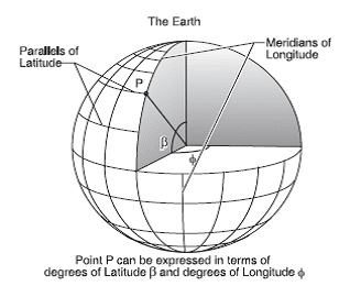
This is the direction of the geographic North Pole, which lies on the Earth’s axis of rotation. The direction is shown on maps by the meridians of longitude.
Grid North
During drilling operations, we are working on a curved surface (i.e., the surface of the Earth). Still, when we calculate horizontal plane coordinates, we assume we are working on a flat surface. It is impossible to represent part of the surface of a sphere on a flat well plan. Corrections have to be applied to the measurements. Many different projection systems can be used.
UTM System
Let us examine the Universal Transverse Mercator (UTM) System as an example of a grid system. In the transverse Mercator projection, the surface of the spheroid chosen to represent the Earth is wrapped in a cylinder that touches the spheroid along a chosen meridian. (A meridian is a circle running around the Earth, passing through the North and South Poles.)
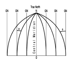
The meridians of longitude converge towards the North Pole and therefore do not produce a rectangular grid system. The grid lines on a map form a rectangular grid system, the Northerly direction of which is determined by one specified meridian of longitude. This direction is called Grid North. It is identical to True North only for the specified meridian.
The relationship between True North and Grid North is indicated by the angles ‘a’ in Figure 2. Convergence is the difference in angle between grid north and true north for the location being considered.
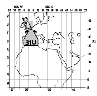
The reference meridians used are 6° apart, starting at the Greenwich meridian, which means the world is divided into 60 zones. The zones are numbered 0 to 60, with zone 31 having the 0° meridian (Greenwich) on the left and 6° East on the right. Each zone is further divided into grid sectors – a grid sector covering 8° latitude starting from the equator and ranging from 80° South to 80° North. The sectors are given letters from C to X (excluding I and O).
Therefore, each sector is uniquely identified by a number from 0 to 60 (zone number) and a letter. For example, sector 31 U, shown in Figure 3, is the Southern North Sea.
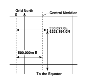
Coordinates in the UTM system are measured in meters. North coordinates are measured from the equator. For the Northern hemisphere, the equator is taken as 0.00 m North; for the Southern hemisphere, the equator is 10,000,000 m North (to avoid negative numbers). The East coordinates for each sector are measured from a line 500,000 m west of the central meridian for that sector. In other words, the central meridian for each zone is arbitrarily given the coordinate 500,000 m East. Again, this avoids negative numbers.
So UTM coordinates are always Northings and Eastings and are always positive numbers. See Figure 4.
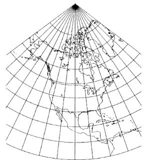
Lambert Projection.
An alternative projection system used in some parts of the world is the conical projection or LAMBERT system, whereby a cone instead of a cylinder cover the spheroid under consideration. This represents meridians as convergent lines and parallels as arcs of circles.
Further discussion of the coordinate systems and map projections is beyond the scope of this text.
Field Coordinates
Although the coordinates of points on a well path could be expressed as UTM coordinates, it is not standard practice. Instead, a reference point on the platform (platform rig) or rig is chosen as the local origin and given the coordinates 0,0. On offshore platforms, this point is usually the center of the platform. The Northings and Eastings of points on all the wells drilled from the platform are referenced to this single origin. This is important for comparing the positions of wells, in particular for anti-collision analysis.
Direction Measurements
Survey tools measure the direction of the wellbore on the horizontal plane with respect to the North reference, whether it is True or Grid North. There are two systems used:
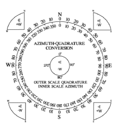
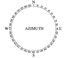
- In the azimuth system, directions are expressed as a clockwise angle from 0° to 359.99°, with the North being 0°
- The quadrant system, In the quadrant system (Figure 5), the directions are expressed as angles from 0°- 90° measured from North in the Northern quadrants and South in the Southern quadrants.
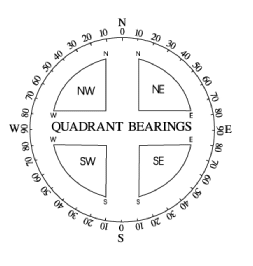
Figure 6 shows how to convert from the quadrant system to azimuth and vice versa and how to apply the correction from Magnetic to True North in the two systems. The subjects of Magnetic Declination Corrections and Grid Convergence Corrections will be dealt with in detail later in the Part on surveying.