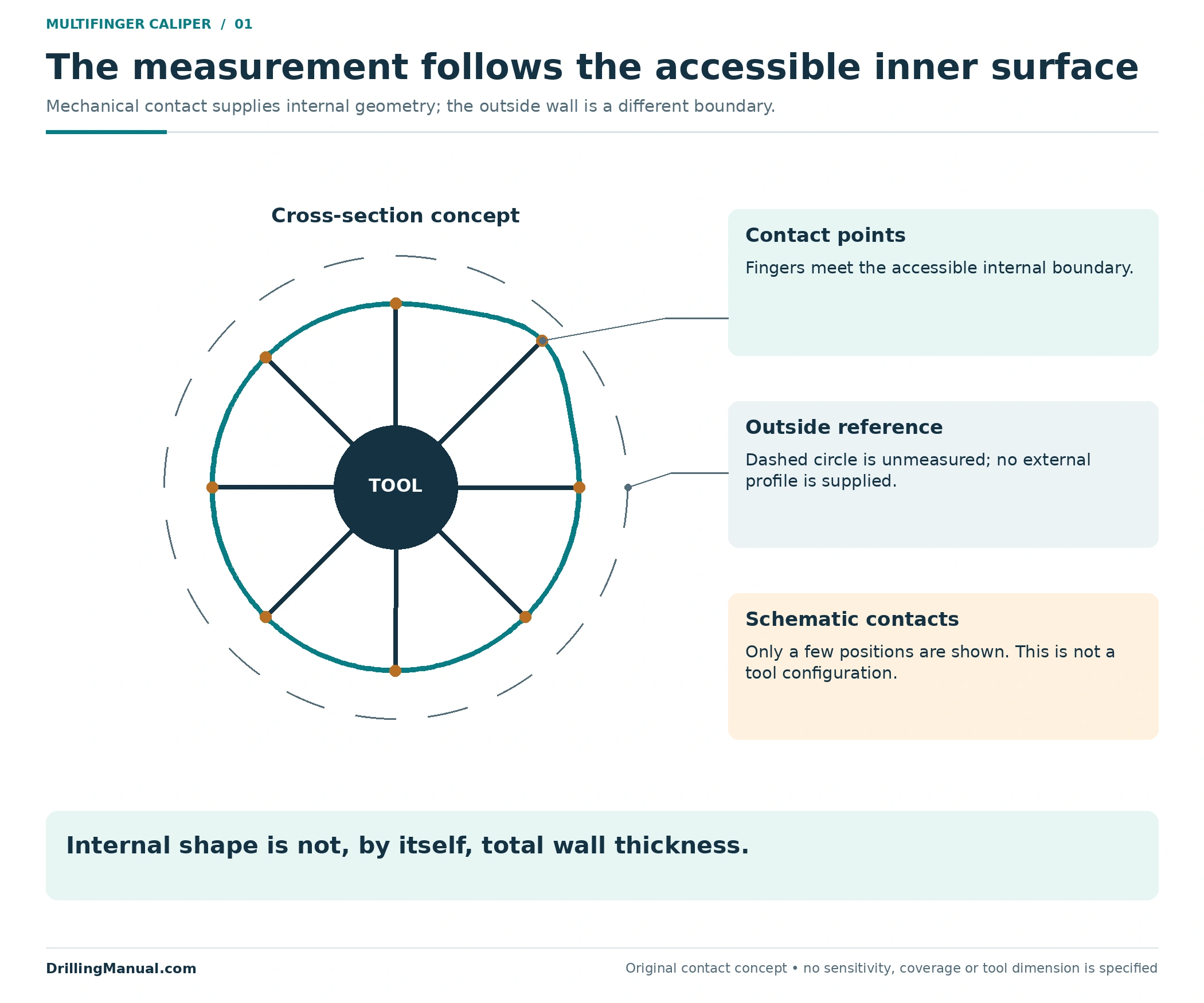
A multifinger caliper records the internal shape of casing or tubing. Its mechanical measuring fingers follow the accessible inner surface, producing information about enlargement, restriction and other departures from the expected profile. That makes it useful for investigating internal damage, but an internal measurement does not reveal every condition of the steel surrounding it. [1, pp. 6-11–6-15]
The first interpretation question is therefore geometric: what changed, where did it change, and how much of the available measurement supports that description? The next question concerns cause. A local outward excursion may be consistent with internal pitting or wear; a reduced opening may be consistent with deposited material or deformation. The profile alone should not be made to answer a stronger question than the measurement supports.
This guide explains how to read that evidence before deciding what further inspection or workover assessment is needed. The drawings and numerical cases are original teaching examples. They are not actual logs, tool specifications, acceptance criteria or remaining-strength calculations.
What Does a Multifinger Caliper Measure?
The mechanical measurement concerns the inside of the pipe. Multiple fingers provide information around the internal circumference as the tool moves through the interval. The resulting record can be presented as individual measurements, selected minimum and maximum curves, or a processed display of internal geometry. The source describes several presentations rather than one universal log format. [1, pp. 6-11–6-14]
Before interpreting a track, identify what its numbers mean. A display may contain a radius-related channel, a reported internal diameter or a change from the nominal reference. Those quantities are related, but they are not interchangeable labels. The historical examples contain both summarized calipers and individual-channel information, so the header and processing description matter as much as the visual pattern. [1, pp. 6-12–6-14]
A multifinger caliper is also different from an acoustic image or an electromagnetic pipe-inspection response. Those tools can appear beside one another in a casing-evaluation report while measuring different properties. The Schlumberger chapter deliberately discusses separate methods. Its acoustic borehole-televiewer examples should not be read as mechanical-finger measurements. [1, pp. 6-10–6-15]
Give the Multifinger Caliper a Valid Reference
An anomaly is a departure from a reference, so first identify the pipe and the reference used in the display. A nominal dimension, a measured nearby section and an earlier inspection are different comparison bases. Preserve which one supports the description instead of treating every smooth part of the plot as the original undamaged geometry.
The source’s joint-by-joint example lists mean diameter and departures from nominal alongside the detailed display. That organization connects a feature to a specific pipe interval and dimensional reference. It also shows why a color map without its header or reference dimensions is an incomplete inspection record. [1, pp. 6-12–6-14]
The separate casing pipe specifications guide provides the broader dimensional context. For log interpretation, retain the actual string information used by the analyst. A value copied from a nominal-size description should not silently replace the reference assigned to the inspected interval.
| Reference item | What to identify | Why it affects the reading |
|---|---|---|
| Inspected pipe | Casing or tubing, interval and recorded dimensional basis. | A dimension belongs to the specified string and depth. |
| Channel definition | Radius, diameter, deviation or another processed quantity. | A plotted excursion must be interpreted in the correct units. |
| Nominal comparison | The reference value used in the display or summary. | The reported change depends on that reference. |
| Presentation and processing | Individual channels, summaries, depth scale and relevant corrections. | Processing and display choices determine what information remains visible. |

Three Internal Patterns to Keep Separate
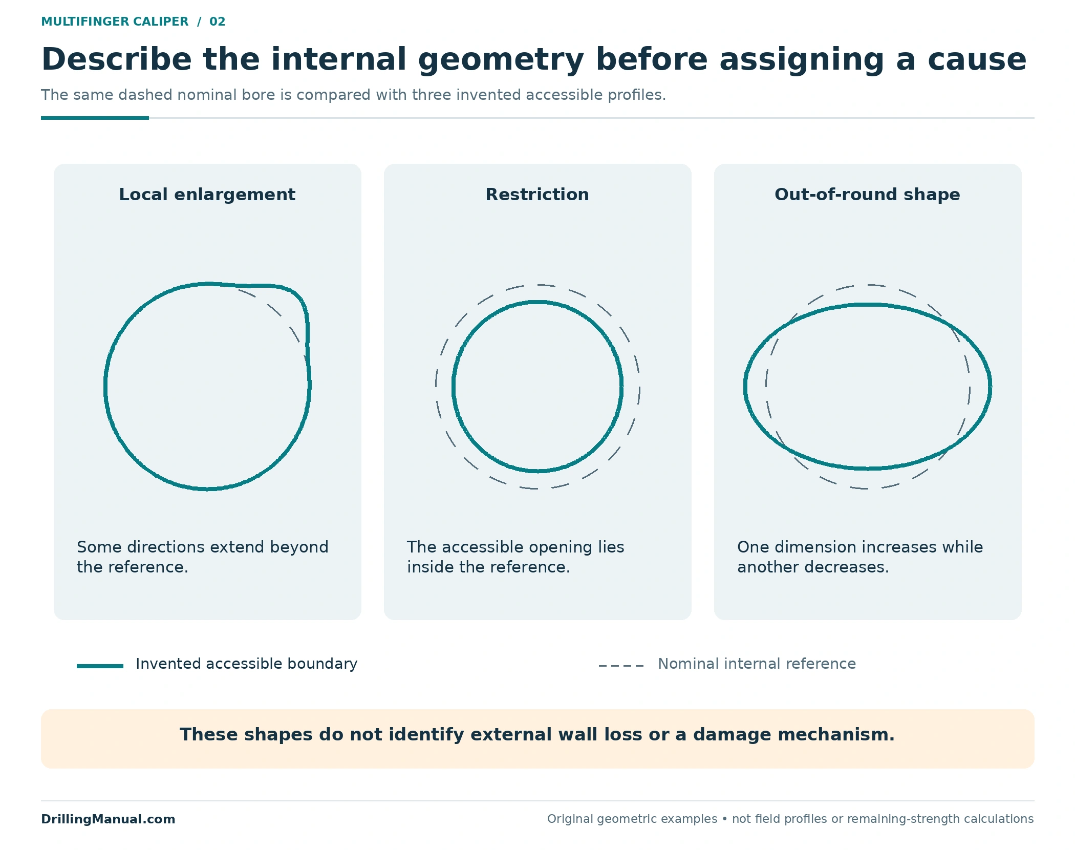
Begin with a description of the profile rather than an immediate repair diagnosis. An enlarged bore, a restricted bore and an out-of-round bore are different geometric observations. Figure 2 places them beside one another using invented cross-sections and the same nominal internal reference. The outer pipe boundary is deliberately not presented as a measured result.
For an enlarged profile, ask whether the increase is local or extends around the measured circumference. A localized outward feature and a broadly enlarged section do not describe the same distribution of internal change. The source relates positive departures to pitting in its multifinger presentation, but a complete interpretation still needs the actual channel pattern and context. [1, pp. 6-12–6-14]
For a restriction, the fingers follow the accessible internal boundary. If material occupies part of the bore, that boundary is not necessarily the original steel surface. The chapter discusses scale buildup in interpreting reduced internal dimensions. Consequently, a smaller opening should not automatically be reported as increased steel thickness. [1, p. 6-13]
A deformed profile requires both the large and small dimensions to remain visible. One direction can become wider while another becomes narrower. Calling that entire section “enlarged” because its maximum increased would hide the restriction in the other direction. This is a geometric interpretation of the original sketch, not a diagnosis of the load that produced deformation.
Read Multifinger Caliper Curves Along Depth
A cross-section describes one location; a depth record shows how the profile changes through an interval. Read the depth coordinate, the reference dimension and the channel definition together. A short local excursion, a change across a joint and a sustained restriction should not be reduced to the same statement that “the caliper moved.”
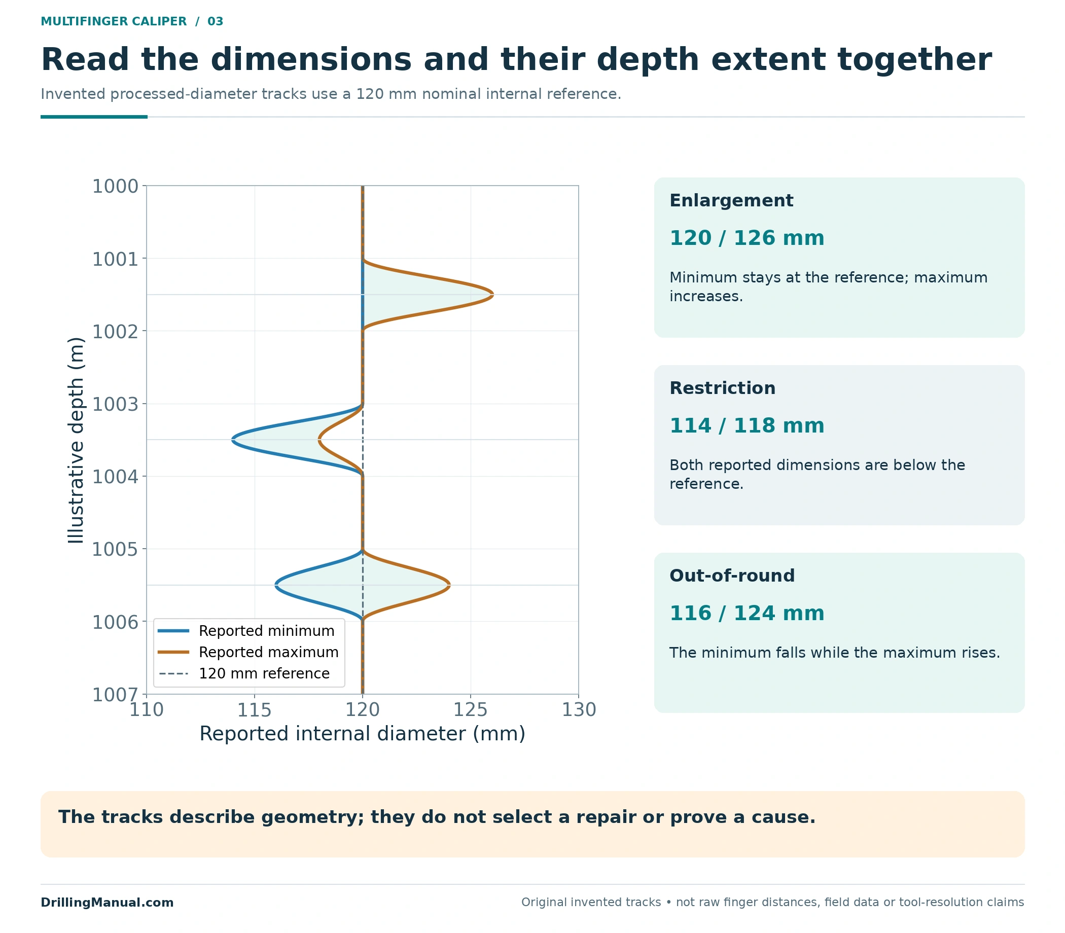
Figure 3 uses a hypothetical reported internal diameter of 120 mm as its reference. At the first illustrated feature, the maximum increases while the minimum remains near the reference. A second feature reduces both reported dimensions. A third separates them in opposite directions. The shapes are constructed to explain the reading, not to represent a particular tool’s resolution or a field defect.
| Invented feature | Reported minimum / maximum | Geometric reading | What it does not establish |
|---|---|---|---|
| Local enlargement | 120 / 126 mm | Some measured internal directions extend beyond the reference. | The damage mechanism or the remaining external wall. |
| Restriction | 114 / 118 mm | The reported opening is smaller than the 120 mm reference. | Whether deposited material, deformation or another condition explains it. |
| Out-of-round profile | 116 / 124 mm | Large and small internal dimensions move in opposite directions. | The cause, severity or acceptability of the deformation. |
These reported dimensions are deliberately labeled as processed diameters. They should not be interpreted as raw distances from an off-center tool. The source notes that eccentricity effects in deviated wells can be compensated. That observation is a reason to check the processing basis, not an assurance that every supplied log has already received the appropriate correction. [1, p. 6-13]
Depth extent belongs beside the dimensional excursion. A single maximum does not say how far the feature continues along the pipe. In a multifinger caliper review, preserve the top, bottom and detailed shape of the interpreted interval on the stated depth basis. Those are observations about where the feature is represented; they do not supply a repair length or establish how far an unmeasured condition extends.
Multifinger Caliper Enlargement Is Not a Wall-Loss Percentage
In the invented enlargement example, 126 − 120 = 6 mm is a difference between reported diameters. It is not automatically 6 mm of pit depth. A perfectly uniform radial enlargement would add 3 mm on each side. A different hypothetical profile could add the entire 6 mm on one side of the maximum span while leaving the opposite side unchanged. The same maximum span does not establish the same local shape.
| Original geometric illustration | Maximum span | What the assumed shape adds |
|---|---|---|
| Reference circular bore | 120 mm | Starting geometric reference. |
| Uniform concentric enlargement | 126 mm | 3 mm on each side of the diameter. |
| One-sided enlargement along that span | 126 mm | 6 mm on one side, with the opposite side unchanged. |
These are alternative constructed shapes, not interpretations assigned to a field trace. The multifinger caliper’s detailed internal pattern helps distinguish geometry; additional information is still needed to relate it to metal loss. Without a defensible wall reference, converting the diameter change into a percentage of remaining steel introduces an assumption that the internal measurement has not resolved.
Why a Multifinger Caliper Cannot Size External Loss
The inner surface is only one boundary of the pipe wall. External metal loss can change the outer boundary without changing the measured bore. The source explicitly distinguishes mechanical and acoustic calipers from its electromagnetic thickness method, whose response includes wall loss at either pipe surface. [1, p. 6-15]
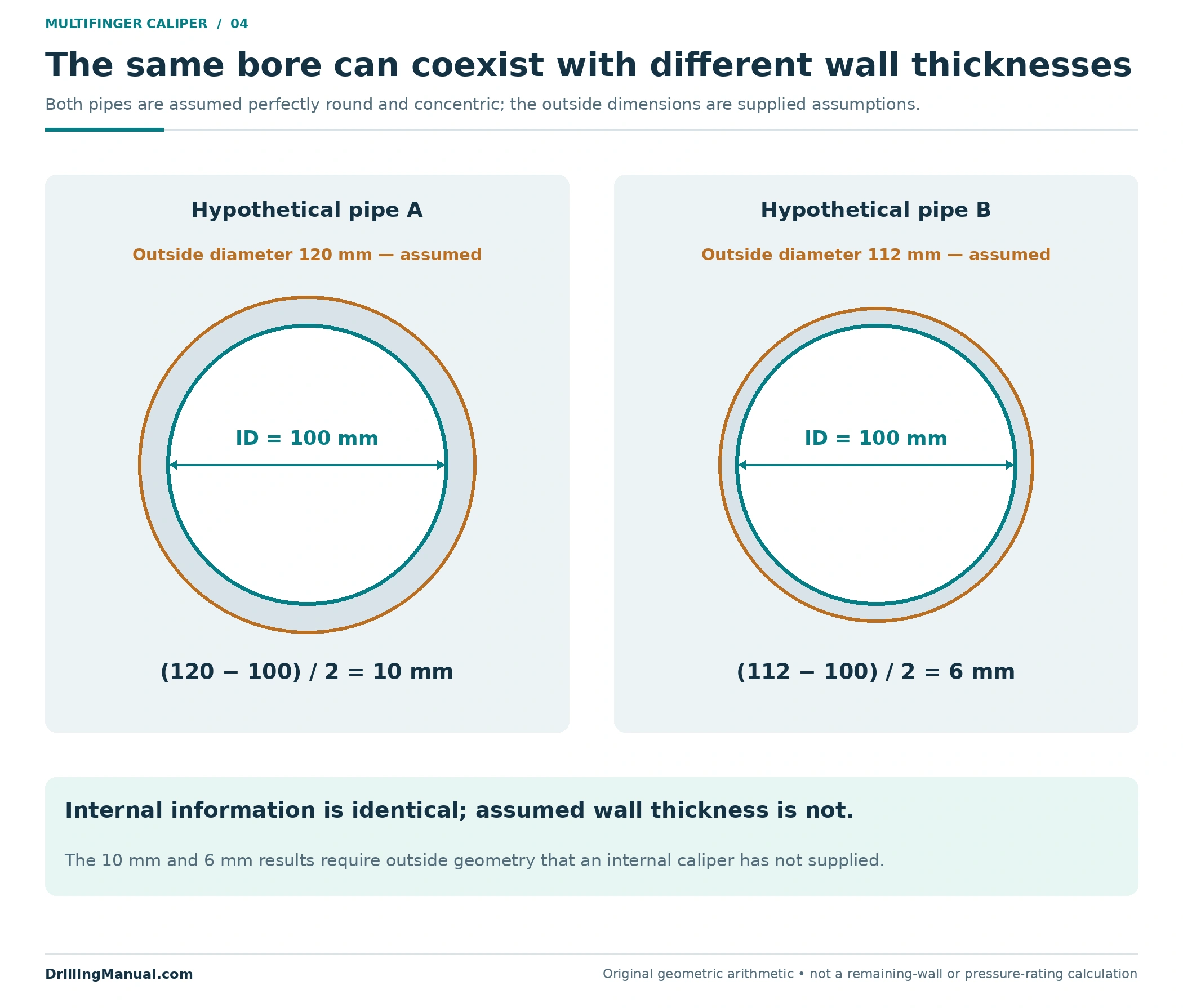
Consider two perfectly round, concentric hypothetical pipes. Both have a 100 mm internal diameter. Pipe A has a 120 mm outside diameter; Pipe B has a 112 mm outside diameter. Their geometric wall thicknesses are 10 mm and 6 mm because, under these stated assumptions, thickness equals half the difference between outside and inside diameter.
The multifinger caliper could present the same 100 mm bore in both cases. The difference between 10 mm and 6 mm comes from the assumed outside dimensions, which the internal measurement has not supplied. Drawing a nominal outside circle around an internal profile does not convert that reference into a measured external boundary.
| Hypothetical geometry | Internal diameter | Assumed outside diameter | Calculated wall thickness |
|---|---|---|---|
| A: round and concentric | 100 mm | 120 mm | (120 − 100)/2 = 10 mm |
| B: round and concentric | 100 mm | 112 mm | (112 − 100)/2 = 6 mm |
This example is not a remaining-wall calculation for an actual corroded pipe. Real local geometry need not satisfy its round, concentric assumptions. Its purpose is narrower: identical internal information can coexist with different wall thicknesses. Therefore, internal geometry alone cannot uniquely determine the external loss.
Keep Individual Measurements Beside the Summary
Minimum and maximum curves make a long record easier to review, but they discard part of the distribution. The source describes a presentation that reports selected maxima and minima for sectors of the circumference. It also shows a multifinger display with individual channels and a joint-by-joint listing. These are complementary views, not equivalent amounts of information. [1, pp. 6-12–6-14]
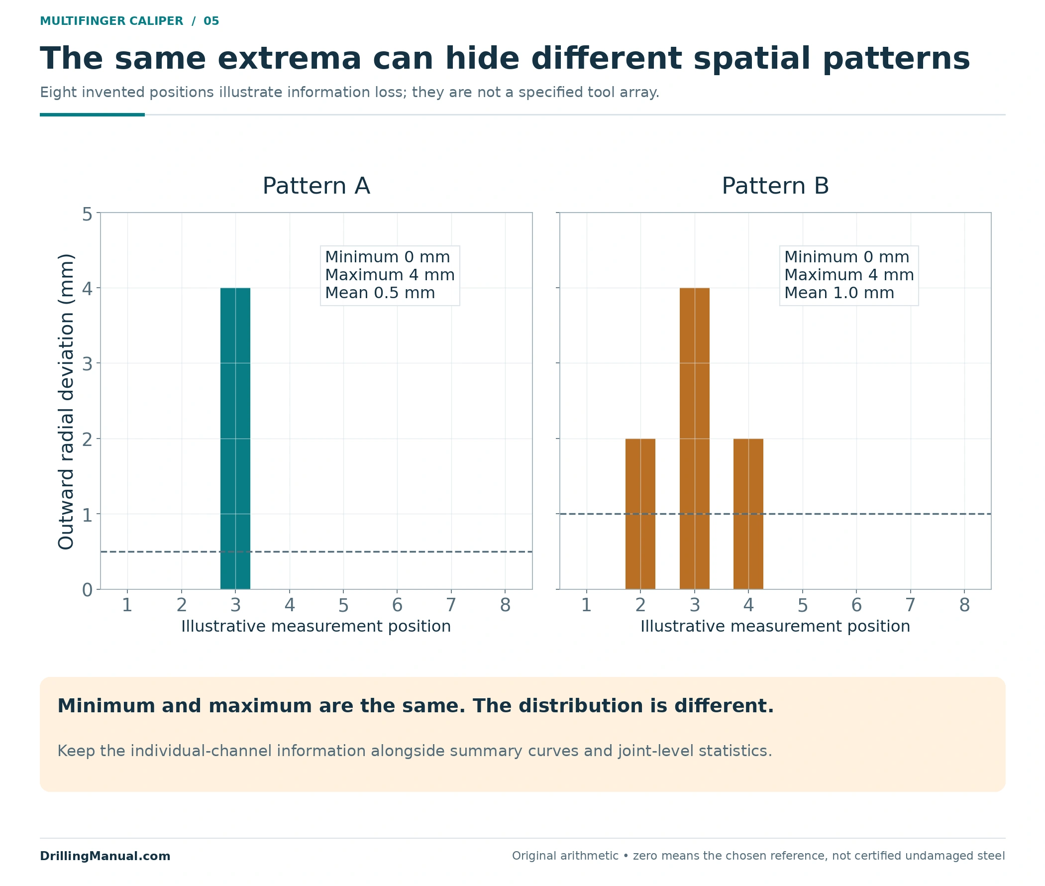
Figure 5 makes that distinction with eight invented measurement positions. Pattern A contains one localized outward excursion. Pattern B has the same maximum excursion but additional changes at neighboring positions. Both share the same minimum and maximum. Their spatial patterns still differ, so the two summary values cannot reconstruct the complete internal shape.
The eight positions are an arithmetic illustration, not a proposed tool configuration. Their purpose is to show information loss in a summary. For a real multifinger caliper record, establish what individual measurements and processing outputs are available before treating a maximum value as a complete description of the affected surface.
Using outward radial deviation in millimeters, Pattern A is 0, 0, 4, 0, 0, 0, 0, 0; Pattern B is 0, 2, 4, 2, 0, 0, 0, 0. Both have a minimum of zero and maximum of four, while their means are 0.5 and 1.0 mm. The example shows exactly which information the extrema retain and which they omit. None of those statistics supplies an external wall measurement.
A mean value answers another question again. It can help describe a joint overall, while a localized feature remains important within that joint. Reporting the mean alone can hide the feature; reporting only the extreme can hide how localized it is. Retaining both the overview and the detailed evidence makes the interpretation easier to challenge and reproduce.


Check Display Scale and Measurement Context
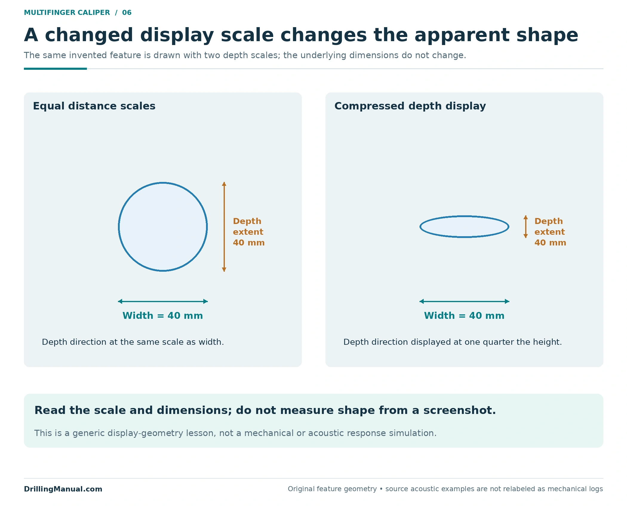
An image can make a feature look longer, shorter or flatter depending on its display scales. In its acoustic examples, the source explicitly explains that different horizontal and vertical scales distort apparent shape. That is a presentation lesson; it does not make the acoustic response a mechanical-caliper measurement. [1, pp. 6-10–6-12]
Figure 6 applies the same elementary geometry to an original invented feature. One panel preserves equal distance scales, while the other compresses the depth direction. The displayed shape changes although the underlying feature does not. Read dimensions from the declared scale and data, not from the apparent aspect ratio of a screenshot.
The color legend deserves the same attention. In an original teaching map, zero can mean no departure from the selected nominal reference, while positive values mean an outward change. That does not make zero a certificate of undamaged steel or turn a color into a percentage of wall loss. For a supplied multifinger caliper image, use its own legend and channel definition. Do not transfer the color meanings or scale from a different presentation simply because the two images look similar.
The chapter also shows why a conspicuous excursion should be checked against completion features. Its examples identify normal collar responses separately from damage, and the mechanical-caliper example labels a collar and a localized hole in different parts of the same record. A repeated joint-related feature is not automatically corrosion simply because it produces a large deflection. [1, pp. 6-11–6-13]
A useful review asks whether the depth correlation, individual channels and available repeat observations support the same feature. This is an editorial evidence check, not a prescribed logging program. The source’s acoustic examples demonstrate the risk of missing small features and the value of expanded presentations; the actual mechanical tool and acquisition record must establish their own coverage and limitations.
A Multifinger Caliper Profile Is Not a Pressure Test
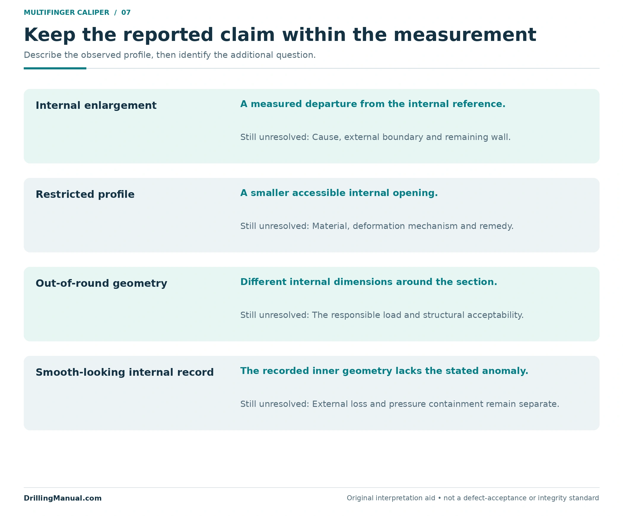
An internal shape record cannot, by itself, demonstrate pressure containment. It does not apply and assess the full pressure differential of a containment test, and it does not provide every dimension needed for a remaining-strength assessment. A smooth-looking bore and an acceptable pressure boundary are therefore different conclusions.
Likewise, a local anomaly does not automatically establish a through-wall leak. The source includes a mechanical-caliper example whose interpretation was checked against recovered damaged casing. That supporting evidence matters: the example is not permission to label every outward excursion as a confirmed leaking hole. [1, pp. 6-12–6-13]
Place the multifinger caliper result within the question being investigated. If the unresolved issue is external wall loss, choose evidence capable of addressing that boundary. If the question is the well’s broader containment performance, the well integrity guide addresses a different assessment. The cement bond log guide is another separate measurement topic, not a substitute name for internal pipe profiling.
Use the Profile to Define the Next Question
The inspection is most useful when it narrows the location and character of the problem. A review can preserve the affected depth interval, the dimensional reference, the observed pattern and the remaining uncertainty. That turns a dramatic-looking image into information that can support a repair assessment.
The casing repair guide and casing patch guide cover remedial topics separately. A multifinger caliper anomaly does not select one of those remedies automatically. The assessment still has to connect the identified condition with the repair objective and the required evidence for that decision.
The same discipline applies to access. A reported local internal dimension is useful information, but it is not a complete approval for a particular intervention assembly. This article does not specify tool clearances, allowable deformation, pressure derating or a repair program. The broader workover operations guide provides the intervention context.
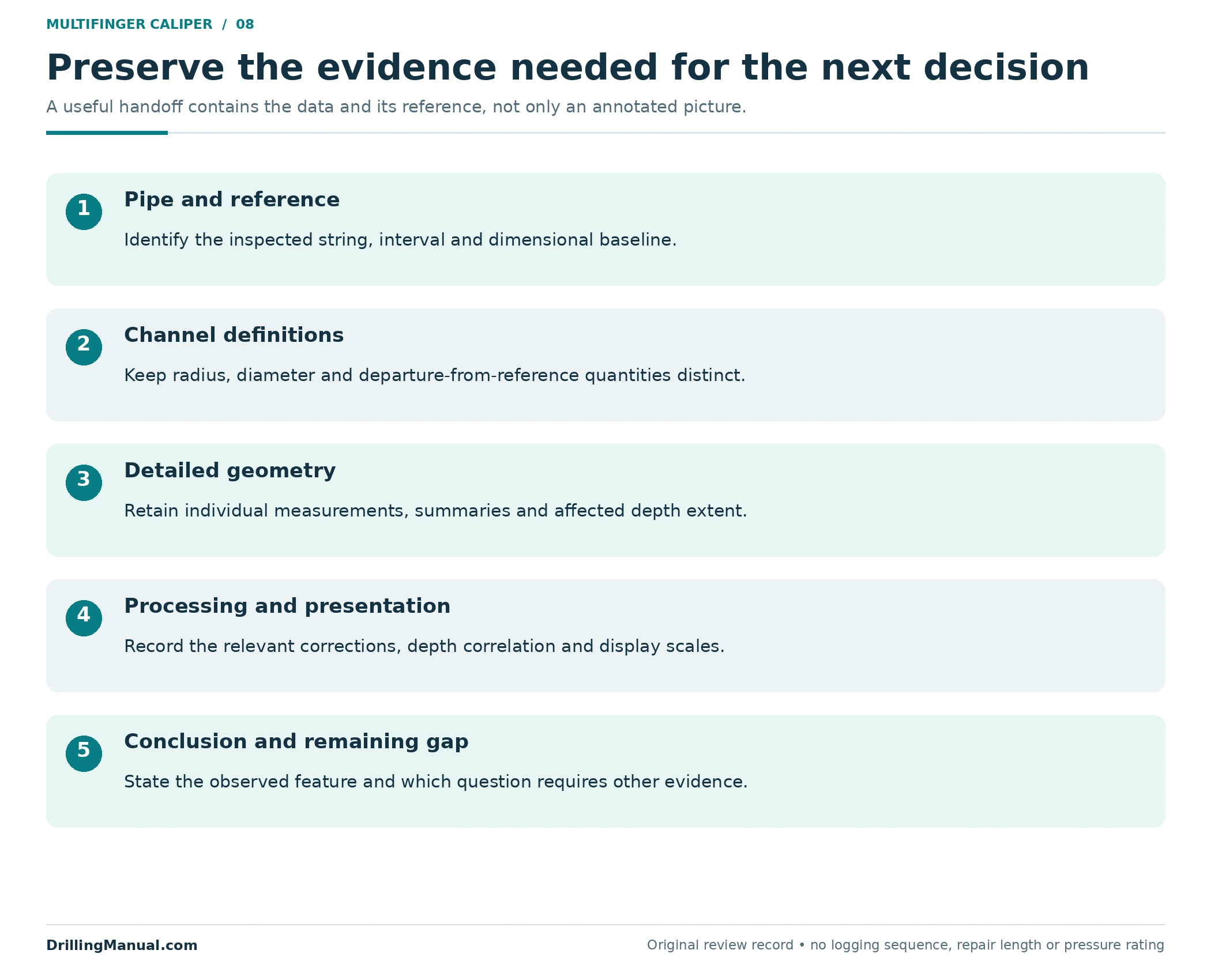
Before handing the result to the next engineer, retain the data rather than only an annotated picture. Include the pipe reference, depth basis, channel definitions, processing information and the supporting detailed views. State what the inspection found and identify the question it leaves unanswered. The resulting record should make it possible to revisit the conclusion without recreating the interpretation from a compressed screenshot.


Questions About Internal Pipe Inspection
Can a multifinger caliper identify internal corrosion?
It provides internal-profile evidence that can support an interpretation of pitting or other internal loss. Keep the measured geometry separate from the proposed cause, and retain the detailed channels and context supporting that interpretation. [1, pp. 6-11–6-14]
Can the same log measure external corrosion?
Not from internal geometry alone. The external boundary can change while the bore remains unchanged. The source distinguishes calipers from thickness-sensitive methods that can respond to external loss. [1, p. 6-15]
Does a smaller reported diameter mean thicker steel?
No. The accessible inner surface may include deposits, and a restricted or deformed profile is not a direct steel-thickness measurement. The source specifically includes scale buildup in its internal-profile interpretation. [1, p. 6-13]
How many fingers should the tool have?
There is no universal number in this guide. The historical source describes configurations that vary with tool size. Assess the actual selected tool, available measurements and inspection objective rather than treating one historical finger count as a current specification. [1, p. 6-11]
Does the largest excursion prove a hole?
No single summary value provides that conclusion by itself. Review the detailed pattern, completion context and supporting evidence. In the source’s mechanical-caliper example, recovered casing provides an independent check on the interpreted damage. [1, pp. 6-12–6-13]
Can a good-looking profile prove well integrity?
No. It describes the measured internal geometry under the inspection conditions. External wall condition, remaining strength and pressure containment require evidence beyond that internal profile. Keep the reported conclusion within the measurement’s scope. [1, pp. 6-13–6-15]
Book Reference
- Schlumberger, Cased Hole Log Interpretation: Principles/Applications, copyright 1989, fourth printing March 1997, SMP-7025. Chapter 6, “Corrosion Evaluation of Casing and Tubing,” printed pp. 6-10–6-15, physical PDF pp. 113–118 in the supplied 185-page copy. Mechanical multifinger discussion and displays: pp. 6-11–6-14; external-loss measurement distinction: p. 6-15. Acoustic examples on pp. 6-10–6-12 are used only to explain method separation and display-scale limitations.