Two wells need repairs. In the first, a failed gas-lift valve sits in a side-pocket mandrel designed for wireline retrieval. In the second, by contrast, the job is to recover and replace a damaged joint of production tubing. Although both are completed wells, only the second job requires equipment that can pull and handle the tubing string. That distinction is the starting point for planning workover operations: what has to move, and what can stay in the well? [1], [2]
What Are Workover Operations?
Workover operations are remedial jobs on an existing well to repair equipment, restore performance or change the completion. A completion is the arrangement of tubing, packers and other equipment that connects a producing or injecting interval to the surface. When the work can pass through that arrangement, a conventional rig may be unnecessary. When the arrangement itself must come out, the unit must be able to recover it. [1], [2]
Terminology varies. Perrin distinguishes routine servicing, such as a wireline valve exchange, from a workover requiring heavier equipment. Nevertheless, both may appear on an intervention schedule. For clarity, describe the deliverable: “replace the valve insert” and “recover the tubing string” tell the planner more than “send a workover unit.” [1]
Workover Rig vs. Drilling Rig: What Is the Difference?
A drilling rig must be able to construct a wellbore, whereas a workover rig is selected to service an existing well. Both can have a mast, hoisting equipment, pumps and pressure-control equipment. Their capabilities still overlap. For example, a drilling rig can undertake a workover, and some workover rigs can rotate a workstring and mill. The difference that matters for a particular job is the equipment actually on offer. [1]
In Figure 1, trace two paths. The mast and traveling block form part of the load path that lifts the string, while the tank and pump serve the fluid path for circulation. A unit may have enough lift for the tubing and still lack the pumping or rotary equipment needed later in the job. For individual component names and functions, see the illustrated rig components guide. [1]
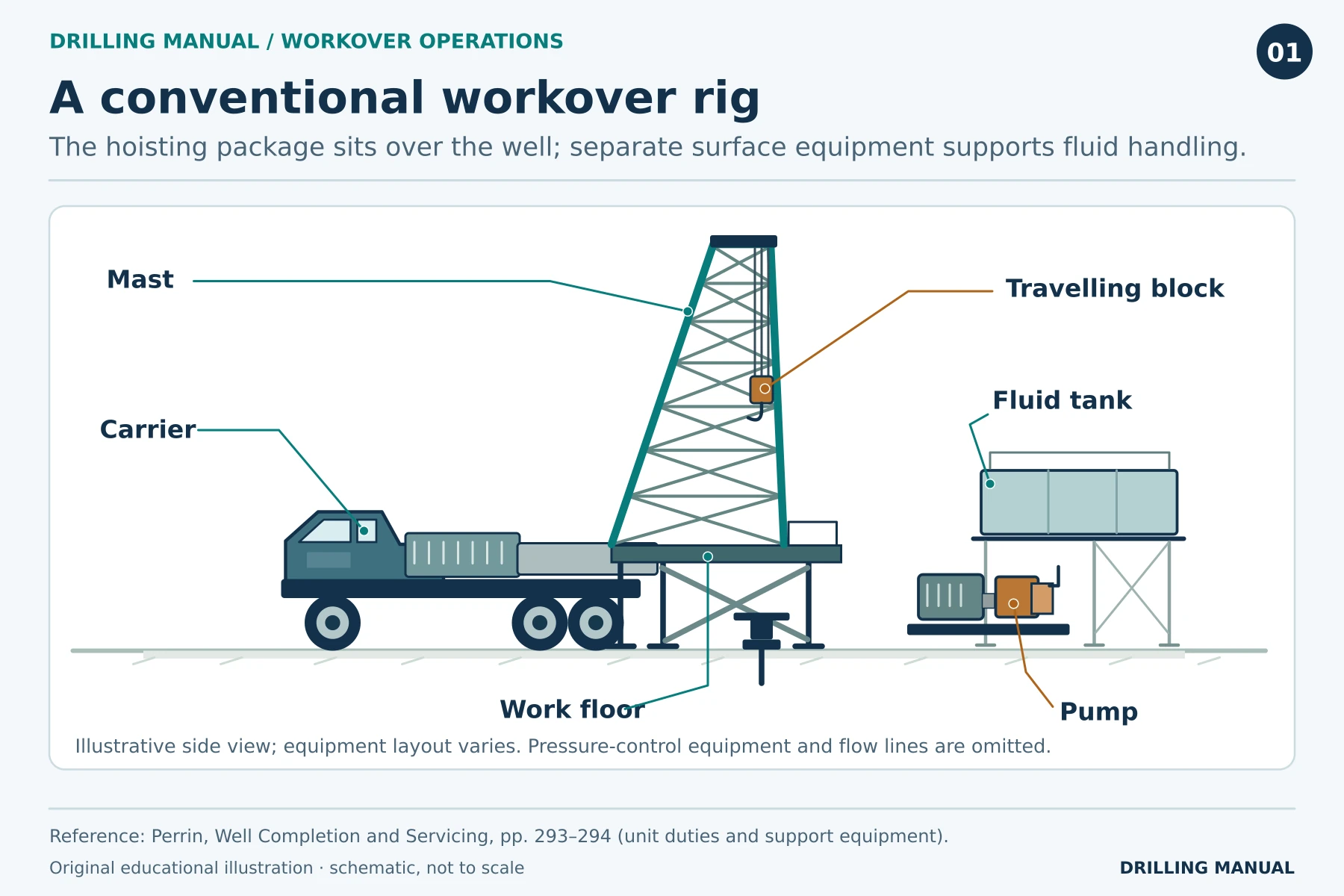
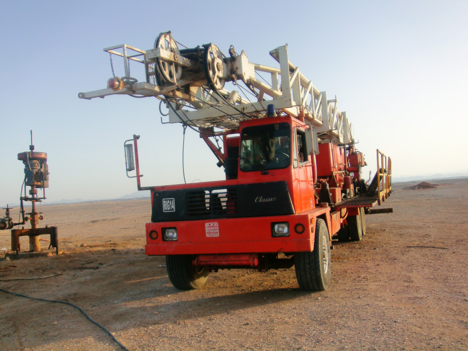
Photo: Kamal Osama Elgazzar / Wikimedia Commons (CC BY-SA 3.0), resized.

Applications: Which Problems Can Workover Operations Solve?
Repair a mechanical fault. For example, a leaking tubing joint or a packer that no longer isolates the annulus can justify remedial work. However, finding pressure in an annulus does not identify which component failed. First establish the likely communication path; otherwise, pulling tubing may expose sound equipment and leave the original fault unresolved. [1], [2]
Restore production or injection. Sand, deposits or damage near the wellbore can restrict flow. The location changes the job. For example, clearing an obstruction inside the tubing requires access to that obstruction. By contrast, treating damage at the producing interval requires a way to place the treatment there. Both faults can reduce the surface rate, so the rate alone does not tell them apart. [1]
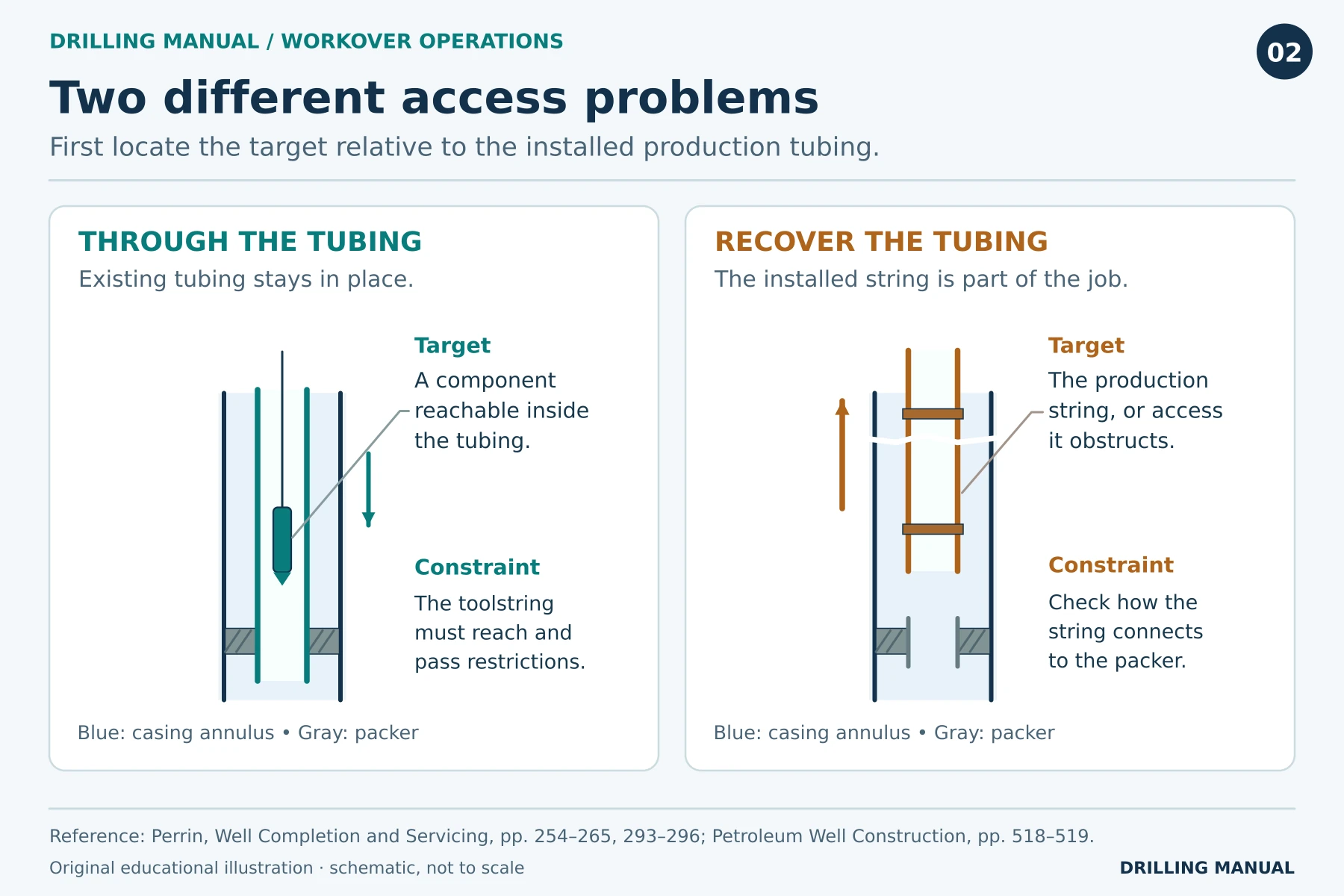
Change the producing interval or equipment. A well may need another zone opened, an unwanted zone isolated, or a different artificial-lift arrangement. Once the objective is clear, check the existing bore, the tubing-to-packer connection and access below the packer to see what can stay. Figure 2 shows why two wells with the same reservoir objective can need different intervention methods. [1], [2]
Does a high water cut tell you which interval to isolate?
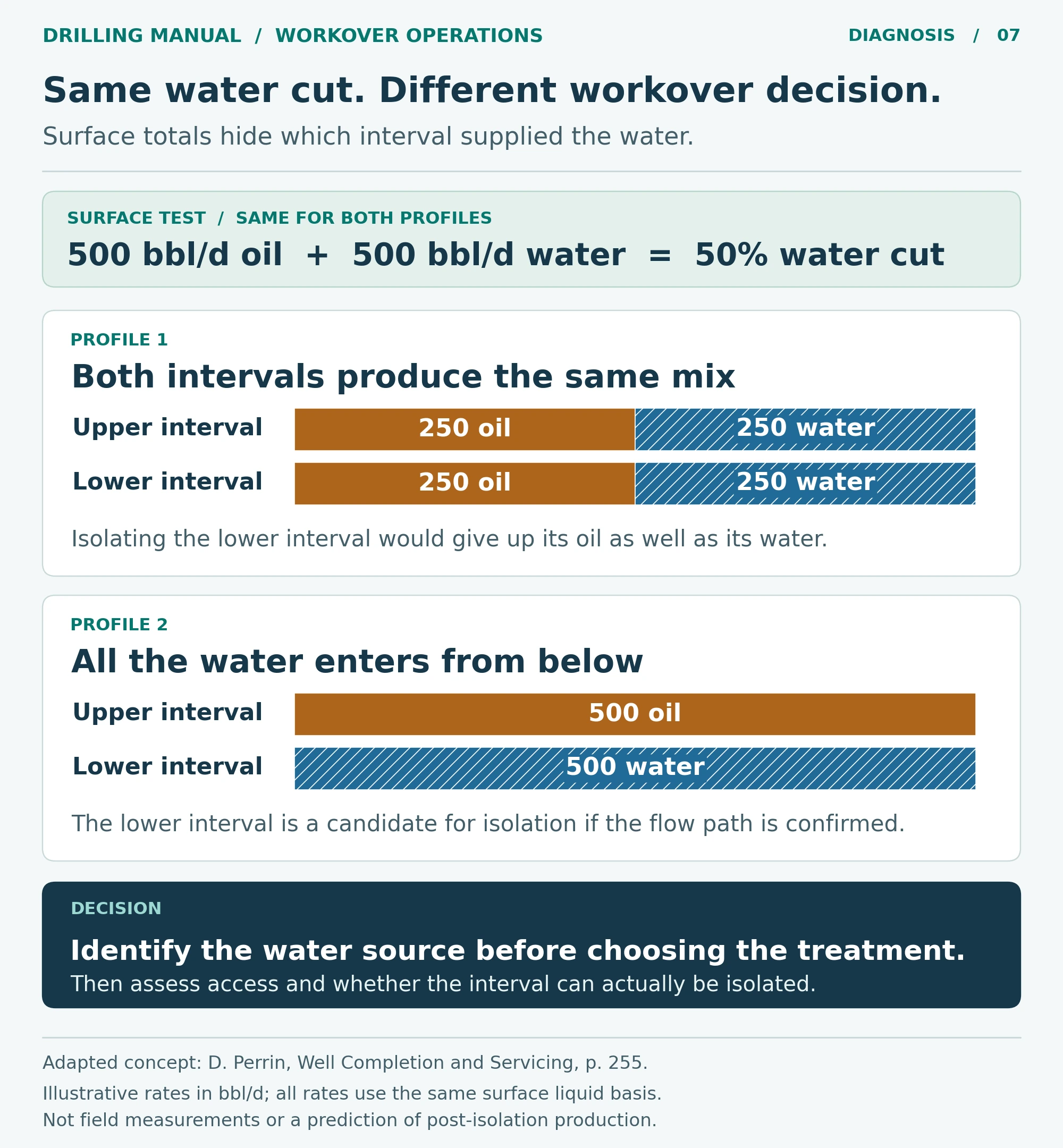
No. Water cut tells you the water fraction of the liquid reaching surface, but not where that water entered. For example, Perrin compares two wells, both at 50% water cut. In one, water enters throughout the perforated interval, whereas in the other it enters from the lower perforations. A production log can help distinguish those patterns. [1]
In the first well, closing the lower interval could sacrifice oil along with water. In the second, the lower interval is a candidate for isolation if selective shutoff is feasible. The same surface measurement therefore leads to different workover proposals. The example illustrates a diagnosis, not a predicted production gain. [1]
Choosing Between Through-Tubing Work and a Rig
If a tool fits the tubing, can it reach and recover the target?
Not necessarily. First, check three things on the latest wellbore schematic and against the well records: the smallest restriction on the route, the profile the tool must engage, and the largest assembly that must come back out. That is why nominal tubing size alone cannot establish access. [1], [2]
A successful gauge run establishes clearance for that gauge. However, it does not prove that a longer toolstring can reach the same depth or that slickline can free a stuck component. For example, inclination and deposits can limit access even when the nominal diameters look adequate. If recovery fails, distinguish an obstruction, a tool that will not engage, and a fish left in the well before deciding whether a heavier unit will solve the problem. [1]
Compare Service Methods for Workover Operations
| Method | Job that suits it | Question that can rule it out |
|---|---|---|
| Slickline | Shift or recover a compatible mechanical insert. | Can the tool pass the restrictions, reach the profile and engage it? |
| Electric line | Run a logging tool that needs a conductor for power or data. | Can the toolstring reach the interval under the actual well conditions? |
| Coiled tubing | Pump through a continuous string while it conveys a tool. | Are reach, circulation and available pull adequate at the target? |
| Hydraulic workover unit | Handle jointed pipe; suitably equipped units can work under pressure. | Can the unit and pressure-control equipment handle the required push, pull and pipe geometry? |
| Pulling unit or conventional rig | Recover and run rods, tubing or a completion assembly. | Can it handle the planned load and also provide any required rotation or pumping? |
These methods overlap. For example, coiled tubing brings a pumping path that slickline lacks. A snubbing unit can handle jointed pipe under pressure when configured for that work. Through-tubing describes the access route, whereas live-well describes the pressure condition. Knowing one does not settle the other. [1]
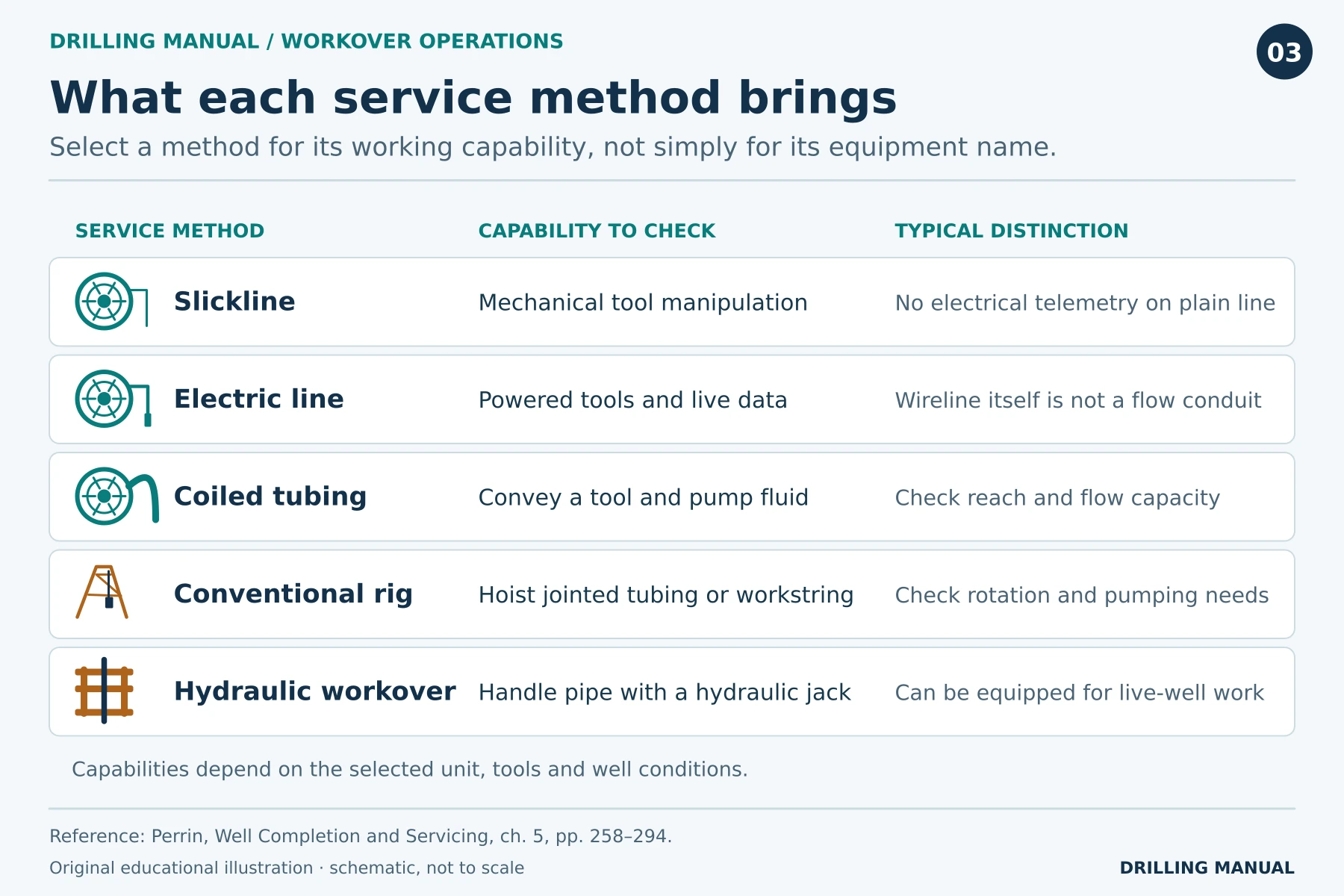
Selecting a Rig for Workover Operations
Load and pipe handling. Identify what will actually be suspended: tubing alone, tubing with a retrievable packer, or a workstring with recovery tools. Check the condition of the old tubing as well as the hoist rating: even a larger rig cannot restore strength to a corroded joint. The installed packer and tubing connection also determine whether the packer should come up with the string or remain downhole. [1], [2]
Rotation and circulation. A straightforward tubing pull and a job that may require milling have different demands. Establish whether the proposed unit can turn the workstring and circulate the required fluid. Also trace the return path. A pump can deliver fluid even when the planned route back to surface is blocked. [1]
Pressure control and the well as it exists today. The well may have different reservoir pressure, fluid levels or completion integrity than it had when first completed. Identify the barriers available at each change in well configuration and how their condition is verified. Use the well-specific program for equipment, limits and operating steps. The well integrity guide explains why a barrier drawn on a schematic and a verified barrier are different things. [1]
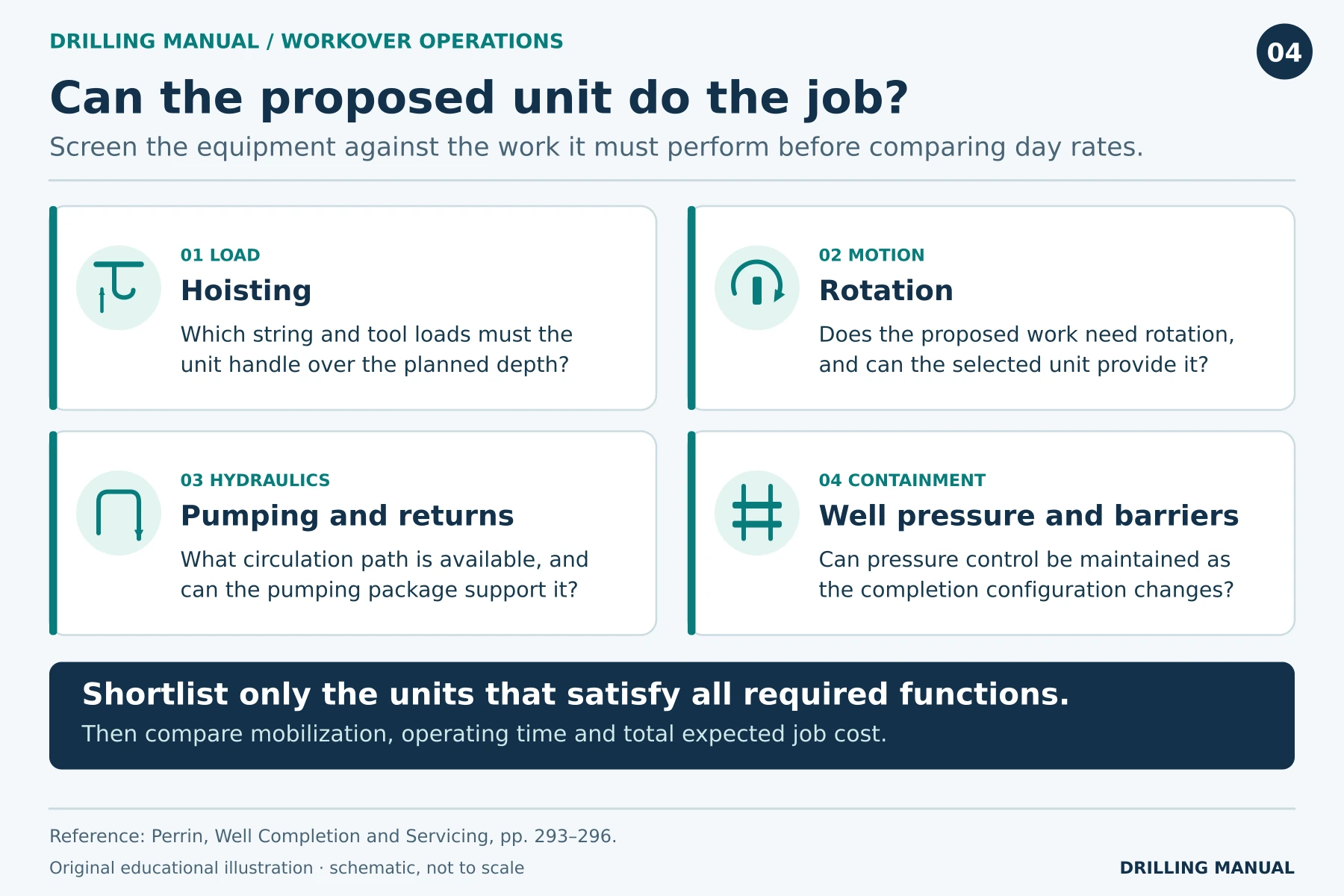
Two Workover Operations Compared: Does the Tubing Have to Come Out?
Well A: Change a retrievable gas-lift valve
Assume the diagnosis identifies the valve insert, the mandrel is sound, and the completion record confirms a compatible side pocket. Because the profile is accessible, a suitable slickline tool can exchange the insert through the production tubing. The completion therefore remains in place. The case for slickline rests on which part failed and how it connects, rather than simply on the fact that the well uses gas lift. [1], [2]
Change one fact: suppose the mandrel body, rather than its insert, must be replaced. Because the body is part of the tubing string, retrieving the insert no longer achieves the repair—even though slickline can still reach it. [2]
Well B: Replace a damaged production-tubing joint
In this case, the diagnosis is complete and the approved repair requires recovery of the damaged joint. A tool inside the tubing can gather evidence, but it cannot bring that joint to surface while leaving the assembled string in place. Therefore the planning question moves from can we reach the damage? to can we recover the required string and install its replacement? [1], [2]
Before choosing the unit, identify the connection at the packer and the condition of the pipe above it. Those details change the recovery plan. A suspected leak on its own would be a different case: until its location and repair objective are established, there is no basis for assuming the same tubing pull. [1], [2]
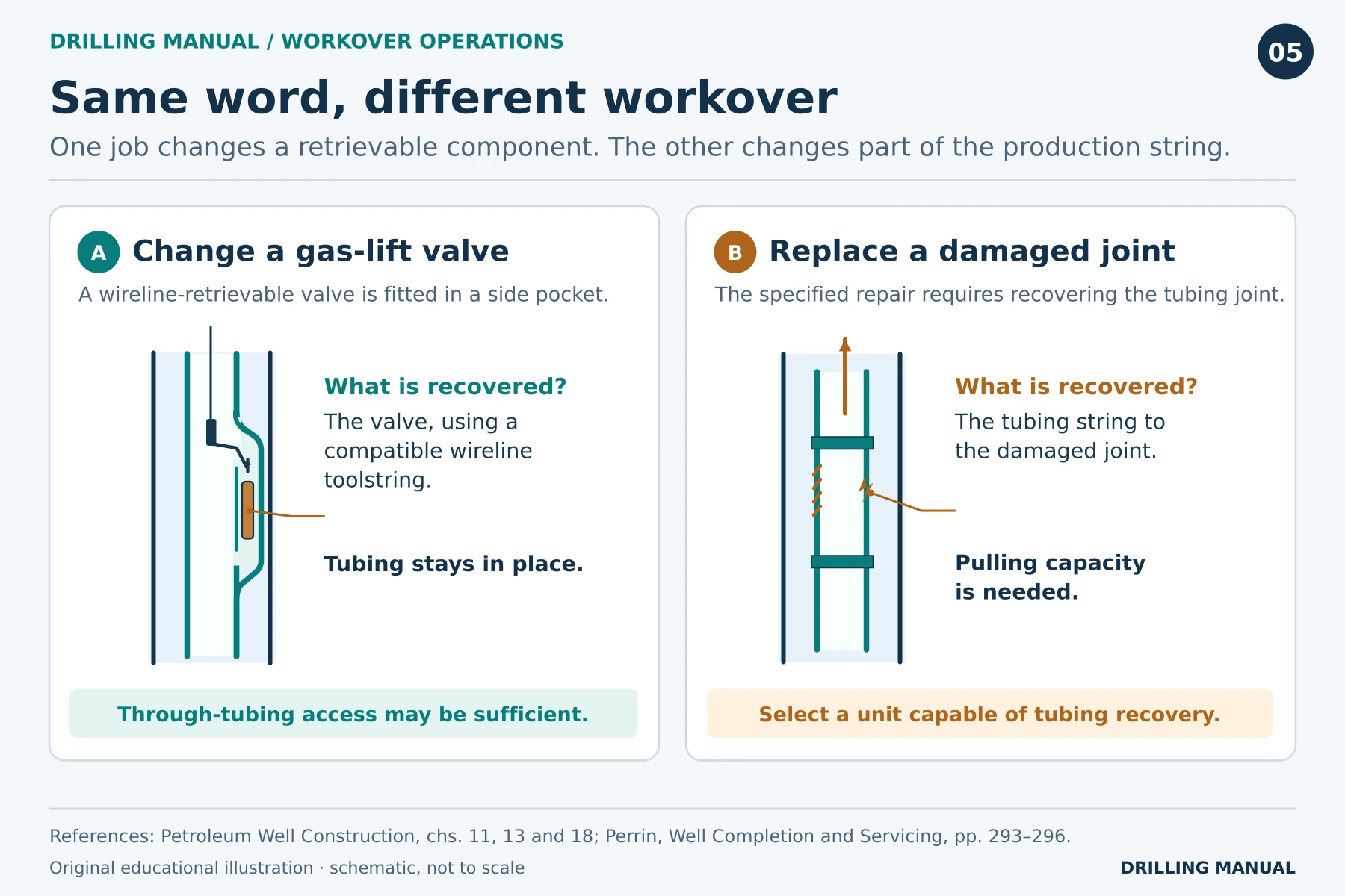
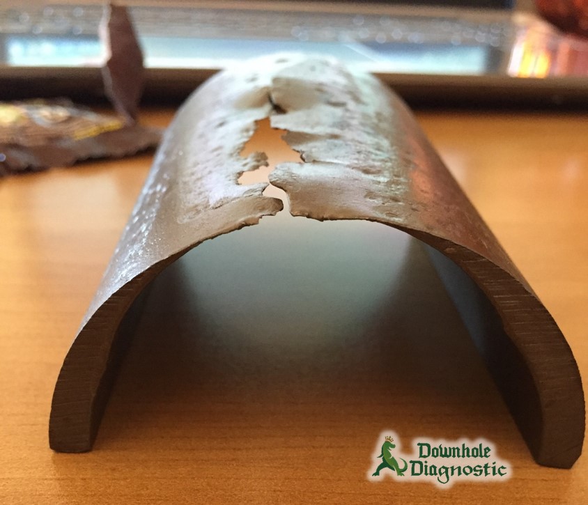
Photo: Downhole Diagnostic, used with credit under the gallery’s reuse terms.
North Sea workover case: Can the leak be isolated without replacing the tubing?
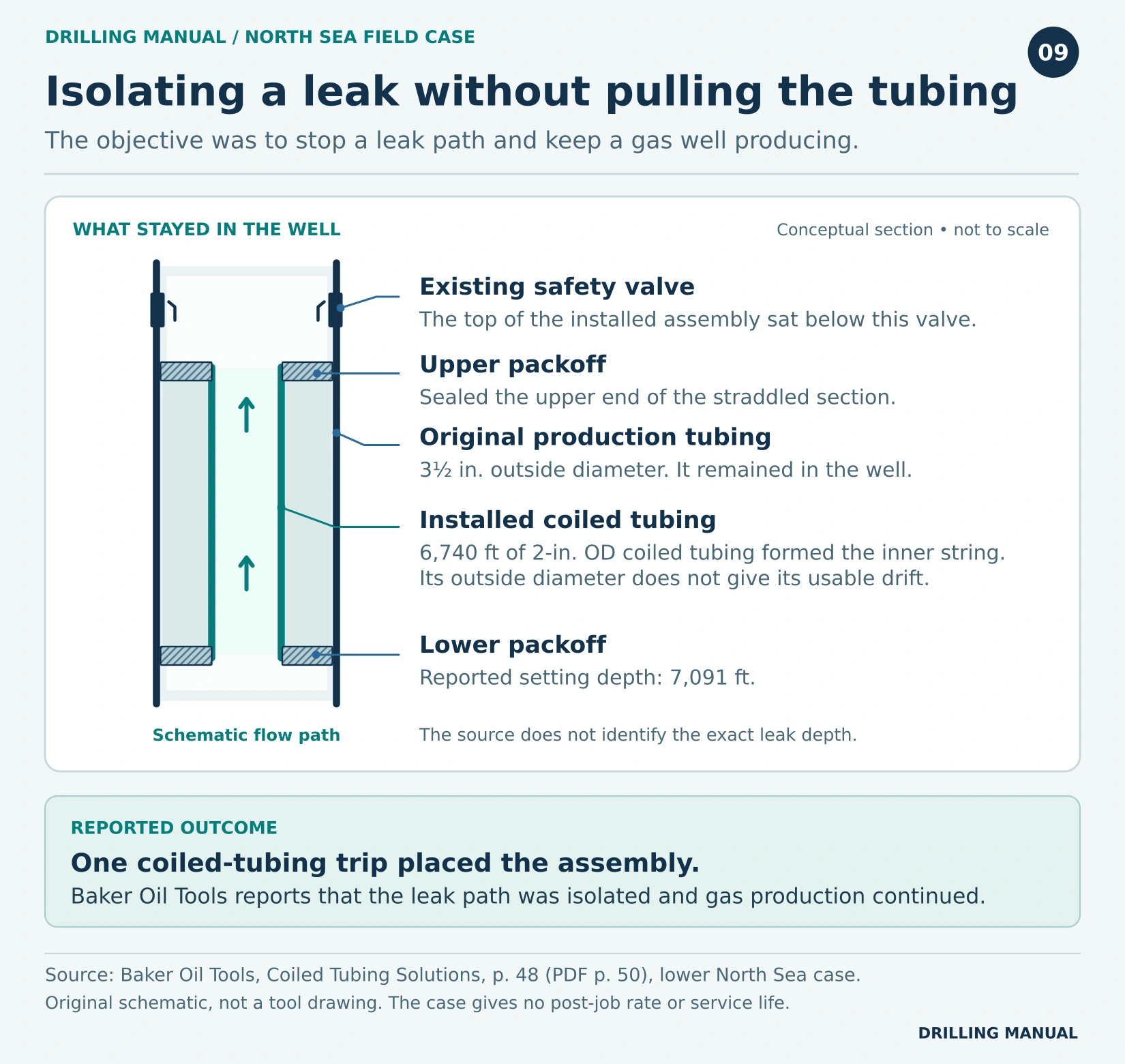
Sometimes. In Well B, success meant bringing the damaged joint to surface. In this North Sea gas well, the operator needed to isolate the leak and keep producing. The acceptable repairs therefore differ. Baker Oil Tools describes installing a straddle inside the existing tubing: it provided a new flow path past the leaking section without recovering the original string. [3]
The host tubing had an outside diameter of 3½ in. The installed straddle included a 6,740-ft length of coiled tubing with a 2-in. outside diameter. It was installed in one trip, with the top below the existing safety valve and the lower packoff set at a reported 7,091 ft. Because both sizes describe outside diameter, neither gives the clear bore available to future tools. [3]
According to the supplier, the straddle isolated the leak and gas production continued. However, the case gives neither the post-job rate nor the service life of this repair. Before applying the idea elsewhere, ask whether isolating the leak meets the required repair objective and whether the remaining bore will allow the next planned intervention. [3]
Statfjord field case: Which completion change made later workovers possible on wireline?
The original Statfjord design described in Petroleum Well Construction lacked zonal selectivity, so changing the producing interval could require a tubing pull. Table 18-5 gives a useful pair of figures: the original safety valve had a 3.3-in. internal diameter; the optimized completion had a 5.75-in. restriction at the safety valve. The larger passage helped preserve access for wireline straddle packers and bridge plugs. [2]
The larger bore did not solve everything. Selective isolation still depended on effective cement isolation around the casing and liner. In addition, some wells with 9⅝-in. casing through part of the reservoir still needed a heavy workover to recomplete downward from an upper zone. For future workover operations, check two separate things: access to the target and isolation behind the casing. [2]
What Do Workover Operations Cost?
First screen the units for technical suitability. Then compare the cost of reaching the same endpoint. For example, consider the fictional tubing job below. Although both units can do it, their expected durations and one-time charges differ. The figures illustrate the calculation and are not market rates. [1]
| Cost assumption | Unit A | Unit B |
|---|---|---|
| Daily operating rate | $18,000 | $26,000 |
| Estimated billable time | 4 days | 2.5 days |
| One-time charges | $30,000 | $22,000 |
| Estimated direct cost | $102,000 | $87,000 |
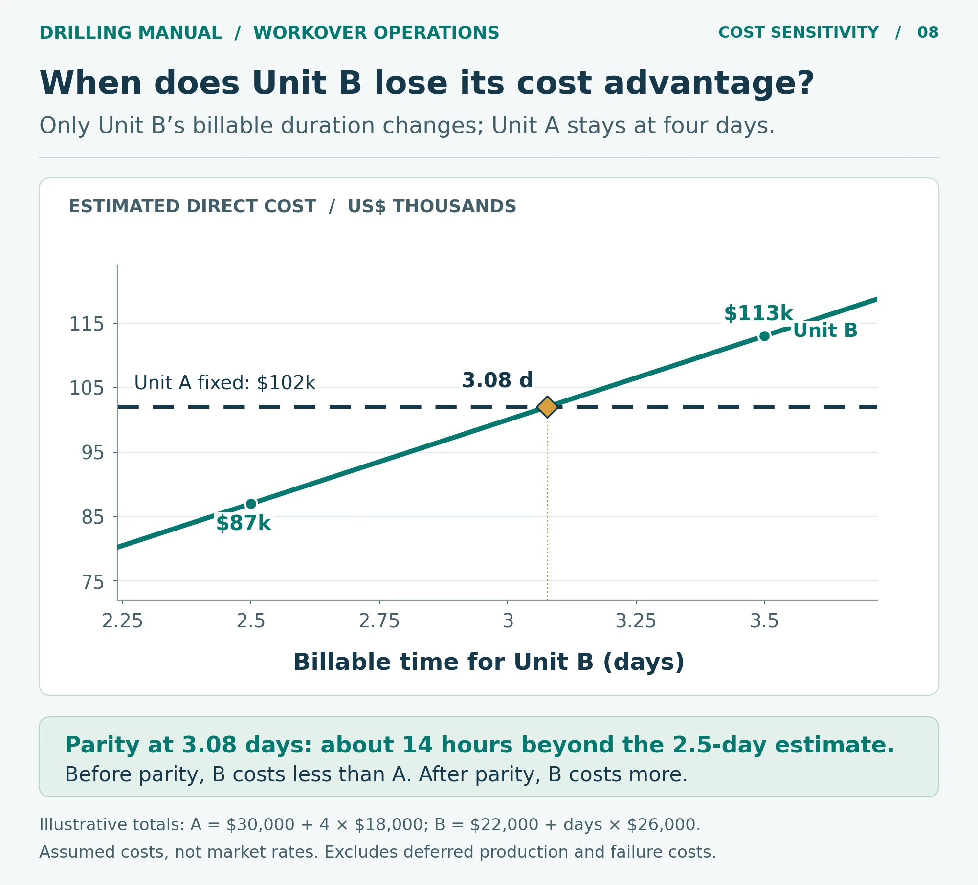
How much delay can Unit B absorb? If Unit A finishes in four days, its direct cost stays at $102,000. For Unit B, the comparable cost is $22,000 + $26,000 × billable days. For example, B costs $87,000 at the planned 2.5 days. The two costs are equal at 3.08 total days for B: ($102,000 − $22,000) ÷ $26,000/day. That leaves only 0.58 extra day, about 14 hours, before B loses its direct-cost advantage.
By contrast, at 3.5 days B costs $113,000, or $11,000 more than A. This crossover holds only while A’s four-day estimate and both one-time charges stay fixed. It compares direct job cost; it excludes deferred production, unsuccessful attempts and costs common to both choices.
Practical Rules of Thumb and Limitations
- Name the item to recover. A gas-lift valve insert, its mandrel and the tubing joint above it are three different scopes.
- Trace the return trip. Before mobilizing, check whether the tool and recovered item can pass the restriction together. The running tool alone may be narrower.
- Keep reach, force and flow separate. Reaching the target proves neither that the unit can release it nor that it can circulate there.
- Define success before mobilization. For a repair, specify the evidence that will verify integrity. For a production job, compare rates at comparable pressures, because an increase in rate alone does not identify what improved.
There is no universal depth, duration or daily rate at which a rig becomes necessary. For example, a shallow job can require recovery of the completion, while a deeper target may remain accessible through tubing. When the completion drawing is uncertain or the string condition has changed, resolving that uncertainty is part of planning the workover. [1], [2]
What happens from planning to handover?
First, use the well history and measurements to define the fault and the evidence needed to close it. Next, confirm access, equipment and barriers against the current completion. After the repair or change, test the outcome against that original objective. For example, a pressure test can address a containment question, whereas a production test can show whether the well delivers at the intended conditions. The exact sequence and acceptance criteria belong in the well program. [1], [2]
Common Questions About Workover Operations
Must every well be killed for a workover?
No. Some interventions can take place under pressure with equipment designed for that service. By contrast, a conventional completion pull is commonly planned on a killed well. The barrier arrangement, well condition and approved method determine what is permissible for the specific job. [1]
Photo: Ciacho5 / Wikimedia Commons (CC BY-SA 3.0).

Is a pulling unit the same as a workover rig?
A pulling unit is principally configured to handle rods or tubing. A workover rig may also offer rotation, circulation and heavy-recovery capability. Rather than choosing from the name on the carrier, check which capabilities the particular unit has and which ones the job needs. [1]
How long do workover operations take?
Estimate time from the specific scope. For example, include mobilization, the number of trips, the work at depth and the test that closes the job. Then price the contingency separately: a recovery attempt can change the schedule even when the target depth stays the same. [1]
Does a successful workover always increase production?
No. For example, a tubing repair can succeed by restoring containment at the previous rate. A recompletion, on the other hand, requires access to the intended zone and evidence that it contributes as planned. Judge the result against the fault or production objective that justified the job. [1], [2]
Book references
- Denis Perrin, Well Completion and Servicing, English edition, Éditions Technip, 1999. Chapter 5, printed pp. 253–259 (diagnosis, servicing and reasons for workover), 276–293 (coiled tubing, snubbing and unit capabilities), and 293–296 (selection, cost, well preparation and completion recovery).
- Petroleum Well Construction, John Wiley & Sons, Halliburton educational version. Chapter 11, pp. 518–520 (tubing-to-packer connections); ch. 13, pp. 627–629 (gas-lift valves and serviceability); ch. 18, pp. 890–895, including Table 18-5 (remedial access and the Statfjord completion comparison).
- Baker Oil Tools, Coiled Tubing Solutions, printed pp. 47–48 (PDF pp. 49–50), “Velocity and Straddle Systems” and the lower North Sea tubing-leak case history on p. 48. The adjacent velocity-string case reports a different well and outcome.