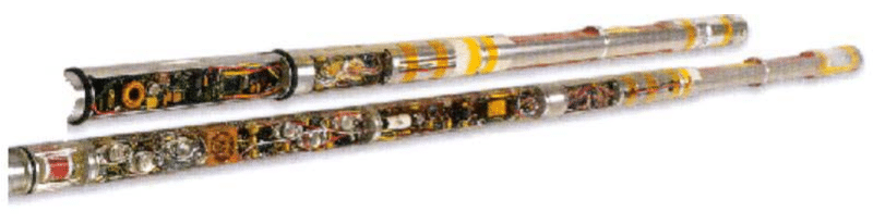
All MWD sensors used in the downhole tool must be rugged enough to withstand the harsh environment. Only one of the systems currently available has the facility to change out damaged components (sensor package/electronics) without tripping the whole bottom hole assembly out of the hole. The failure of one sensor may not necessarily mean that the tool has to be pulled out. Suppose the operator is satisfied that the other sensors are still providing the required information. In that case, the loss of one piece of data may not be significant (e.g. a gamma-ray failure in a directional well, when the operator places more importance on the directional data).
We Can divide The MWD sensors into two categories:
- MWD Sensors For Formation Evaluation
- MWD Sensors For Directional Drilling
MWD Sensors For Directional Drilling
Directional Sensors
MWD tools utilize orthogonal arrays of magnetometers and accelerometers to resolve hole inclination and direction. Highly accurate depth tracking systems measure the drill string and/or block height position and are used to calculate wellbore coordinates at any given point along the well path. MWD tools are currently used as real-time steering tools for orienting and monitoring progress when making kick-off or course correction runs with downhole motors.
Measurement Principle
Wellbore position is expressed in terms of a three-dimensional coordinate system with axes aligned north/south, east/west, and vertically. The attitude of an MWD tool, in relation to the wellbore, is expressed in terms of inclination, azimuth, and tool face angles. Inclination and azimuth angles describe the orientation of the tool’s long axis which coincides with the direction of the wellbore. The tool face angle describes the angle by which the tool, and therefore the BHA deflection device, is rotated within the long axis of the borehole.
Inclination
The inclination is the degree of deviation from a (down) vertical orientation, 0° is vertical and 90° is horizontal. It is also possible to measure angles greater than 90°, which is particularly useful in horizontal well applications.
Azimuth
Azimuth direction is the angle projected in a horizontal plane between the long axis and north. For example, a hole drilled due north has an azimuth of zero, while a hole drilled to the west will be reported as 270 degrees azimuth. Magnetic survey tools determine azimuth concerning magnetic north. A declination correction must be applied if the azimuth is to be referenced to true north. An additional correction may be required to properly reference grid north.
Toolface
The toolface is the orientation of the deflection tool with respect to a fixed point.
Measurement Theory
Attitude of a tool can be determined by measuring the directions of gravity and magnetic field vectors with reference to a coordinate system fixed with respect to the tool. These directions are measured by using arrays of three orthogonal accelerometers and magnetometers.
When insufficient non-magnetic drill collars are in use, it may be advantageous to disregard the measured longitudinal component of the magnetic field, since the spurious field caused by the proximity of magnetic BHA components is closely aligned with the axis of the drill string. In this case, it may be best to measure only two axes and solve for the third axis (or z axis) by using a local total magnetic field value (HTN). Baker Hughes INTEQ offers the D-RAW service for this specific application. In normal use, three-axis measurements will lead to improved accuracy, although this may be dependent in part on attitude. This also permits use of the measured field strength as a to cross-check on survey accuracy.
Pressure Transducer
These electromechanical devices, which convert hydraulic pressure to either a voltage or a current, are used for downhole and surface measurement of pressure. Sensor works by the Wheatstone Bridge concept: a hollow expandable cylinder or diaphragm is wound with copper wire, as the cylinder expands, so does the wire leading to increased resistance and a decrease in current.
MWD Temperature Sensors
This is a solid state device in the downhole electronics which is calibrated to measure temperature over the range from -40 to 175 degrees Celsius.
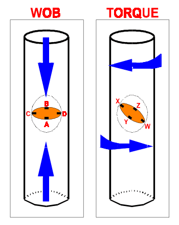
Downhole Weight on Bit / Torque on Bit
Drilling data are particularly important in deviated and horizontal boreholes. Drilling mechanics tools, such as the Baker Hughes INTEQ Drilling Dynamics Gamma (DDG) tool, is able to measure downhole weight on bit, torque on bit, bending moment, gamma-ray, temperature, pressure, and provide full directional control in real-time. The WOB, torque, and bending moment are measured in the same sub (Drilling Subs) which has bonded strain gauges orientated in the direction of the strain to be measured – the WOB and bending moment gauges are placed parallel to the drill collar axis, the torque gauges are positioned at 45-degree angles. Thus, it is possible to discriminate axial and torsional strain and bending moment. The other measurement parameters are housed in the upper transmitter sub. A fully modular version of this tool (Modular Drilling Dynamics – MDD) is now available.
Downhole Shock and Vibration
The MWD sensor assembly is a three-axis accelerometer system that is located in the Modular Tool Controller (MTC) upper-pressure plug and adapter assembly. Its purpose is to monitor and report downhole shock and vibration. The driller and field drilling engineer will be made aware of excessive shock and vibration through mud pulse telemetry so that the drilling conditions can be changed before bottom hole assembly damage occurs.
A “next-generation” DDG tool is able to measure both static and dynamic downhole drilling parameters based on a well site, operator-specified initialization program. These sensors include strain gauges, accelerometers, a magnetometer, and pressure and temperature gauges. The data is processed and compressed, then, on command, sent to a pulsing or recording tool for transmission to the surface and/or downhole storage. The processing of data may be as simple as calculating a time average WOB or as demanding as performing real-time mathematical functions such as complex algorithms to obtain an optimal WOB, RPM, and SPM for maximum efficiency and ROP. Prototype tools were constructed and a successful field test and technical paper have been completed.
Formation Evaluation MWD
Formation evaluation MWD provides accurate, quantitative measurements of resistivity, gamma-ray, neutron porosity, and formation density.
MWD Natural Gamma Ray Sensors
Two basic types of detectors are used by MWD companies in oil and gas to measure gamma rays:
- The Geiger Muller tube is a gas ionization counter consisting of a metal cylinder with an insulated axial wire passing through its center. The cylinder is filled with a non-conductive gas. A high voltage power supply maintains an electrical potential between the central wire and the cylinder. The main detection mechanism is photoelectric absorption or recoil electron ejection from Compton scattering in the metal shield. The detection efficiency of such detectors is not high, even so the method can be improved by the incorporation of gamma ray absorbers (such as silver) to an inner lining of the cylinder.
- With the more efficient MWD scintillation detector used in Baker Hughes INTEQ tools, a crystal of thallium-doped sodium iodide emits light flashes or scintillations when a gamma ray interacts with the crystal. A high voltage photomultiplier tube captures the scintillations, amplifying them into an electrical signal in the form of a count rate. Gamma rays are measured over a specified time in order to collect enough counts to reduce statistical scatter.
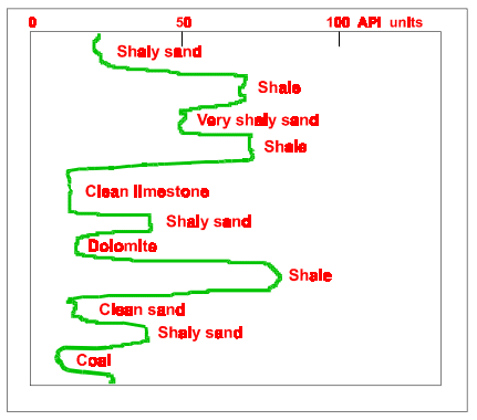
In addition to providing lithologic discrimination, the gamma-ray sensor provides:
- Formation bed boundary and thickness determination
- Well to well structural correlation of beds
- Depth control and casing seat selection
- Estimation of shale fraction in reservoir rocks
- A primary log for sedimentological studies
- Monitoring of injected radioactive materials
- Depth location of radioactive casing PIP tags
Formation Resistivity
The basic measurement used in open hole log evaluation to determine if hydrocarbons are present in a formation is electrical resistance. Electrical resistance is the ability to impede the flow of electric current through a substance. The formation matrix is normally considered an ideal insulator and makes no contribution to formation conductivity. The main conductor, encountered in the earth’s formations, is salt water. This saline water occurs in the formation as free water in the pore space, water adhering to the surface of the rock matrix, or as hydroxyl, ionically bound to clay minerals.
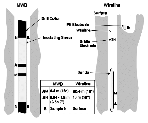
Short Normal Resistivity (SNR)
This MWD tool is very similar to the equivalent wireline tool, except that the return electrode is located on the drill collar itself, rather than a surface return electrode. The SNR tool is a series measuring device. Formation resistivity is measured by passing a constant current from the emitting electrode (A) to the return electrode (N). Please refer to Figure 2. The voltage between the measuring electrode (M) and the return electrode or ground (N) is measured, and formation resistivity is derived from Ohm’s Law:
R = K x V / I
Where:
- R = apparent formation resistivity
- I = current between A and N electrodes (held constant)
- V = voltage measured between M and N electrodes
- k = tool geometric constant
Short Normal Resistivity applications include:
- correlation of marker beds
- identification of casing and coring points
- identification of hydrocarbon zones
- shallow gas detection
- pore pressure determination from shale resistivity
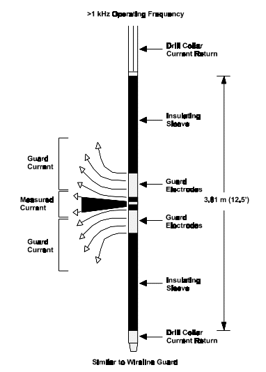
Focused Current Resistivity (FCR)
The MWD FCR sensor uses the same measurement principle as the guard or later log tool of the wireline industry. The sensor utilizes three current emitting electrodes: two focusings and one measurement current electrode. Current is focused on the formation by forcing the voltage of both the focusing electrodes and the measurement electrode to have the same potential. A disc of investigating current perpendicular to the axis of the tool, is focused horizontally into the formation. The current from the focusing electrodes prevents the measurement current, from flowing vertically in the borehole. Like the SNR the FCR is a series measuring device. The current disc passes through the borehole fluid, then into the formation. Both output voltage and current from the measurement electrode are measured. Formation resistivity is calculated from Ohms’s Law using the current and voltage of the measurement electrode. The resistivity is converted to an apparent formation resistivity using the “K” factor of the tool.
FCR applications include:
- quantitative Rt in salt saturated muds
- quantitative Rt in presence of nearby conductive beds
- improved thin bed delineation over SNR
- correlation of marker beds
- identification of casing and coring points
- identification of hydrocarbon zones
- pore pressure determination from shale resistivity
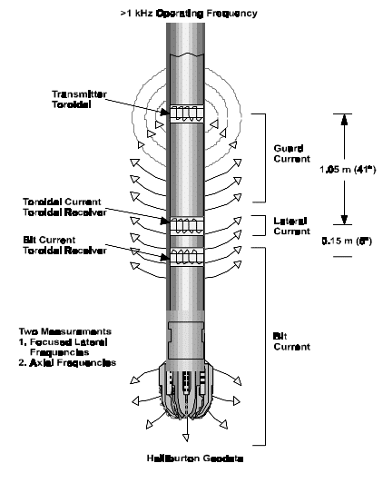
Toroidal Resistivity
The toroidal resistivity tool is based on a proposal by JJ Arps. The tool utilizes the collar as an electrode to provide two resistivity measurements: a focused lateral resistivity measurement and a trend resistivity at the drilling bit. The tool utilizes four toroidal coils covered and protected by insulating shells. A voltage applied from the drive toroid induces an alternating current in the drill string, which is reversed in polarity about the drive toroid. Current leaving the drill string flow through the annulus and formation and returns to the drill string at a point where the polarity is opposite.
Electromagnetic Wave Propagation Resistivity MWD sensor
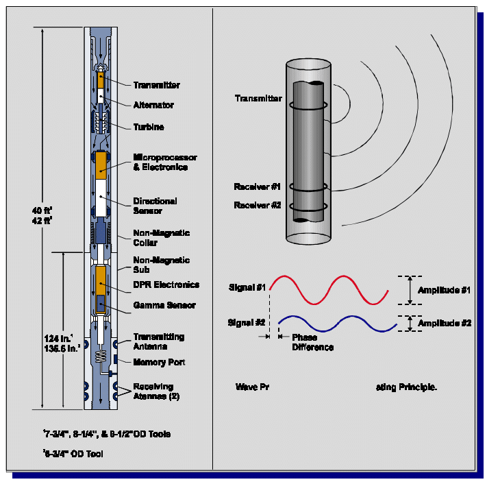
The Dual Propagation Resistivity (DPR) tool is a 2-Mhz electromagnetic wave propagation device that provides two resistivity measurements at different depths of investigation. The tool contains two receiving antennas which are spaced 27.5 and 34.5 inches (69.85 and 87.63 cm) from the single transmitting antenna. Additionally, an MWD gamma-ray scintillation detector is provided for lithology identification.
As the 2-Mhz radio wave travels through the formation and across the two receiving antennas, the phase difference (measured in degrees) and amplitude ratio (measured in decibels, relative to air) of the signal are measured. Resistivities are then derived using a resistivity transform.
The DPR sensor provides accurate resistivity measurements with minimal borehole effects over a wide range of borehole conditions and formation resistivities.
DPR applications include all those associated with Short Normal Resistivity and:
- Resistivity measurements in oil mud and water-based muds
- Dual depth of investigation for invasion profiling
- Moveable hydrocarbon detection
- Excellent vertical resolution (6-inch bed delineation and 2-foot full resolution) for thin bed evaluation in conductive beds
- Accurate Rt measurements for water saturation calculations
- Pore pressure determinations from shale resistivity
Neutron Porosity MWD Sensor
In the wireline, and more recently in the MWD industry, a chemical source that emits neutrons as it decays is used to bombard the formation with high-energy neutrons. They are slowed down from energies of several million electron volts (e.g. 4.5 MeV) to thermal energy of 0.025 eV (electron volts) through a process called elastic collision (they are scattered from the nuclei). The element which plays a dominant role in the slowing down (collision) process is hydrogen. In effect, the neutrons lose and transfer energy when they collide with another particle of equal mass or smaller, such as bound hydrogen nuclei in the form of water or hydrocarbon. The energy loss is equivalent to the amount of hydrogen present in the formation – thus it is possible to derive a hydrogen index. In this respect, it is possible to infer that porosity is a function of the number of neutrons absorbed by hydrogen present in the porous portion of the rock. It should be noted that hydrated clays will also show an elevated porosity. Neutron tools are sensitive to the presence of hydrogen but insensitive to its mode of containment in the formation.
Traditionally, wireline tools have used helium 3 detectors. Geiger-Muller tubes are also used in some MWD and older wireline tools to detect neutron capture gamma rays.
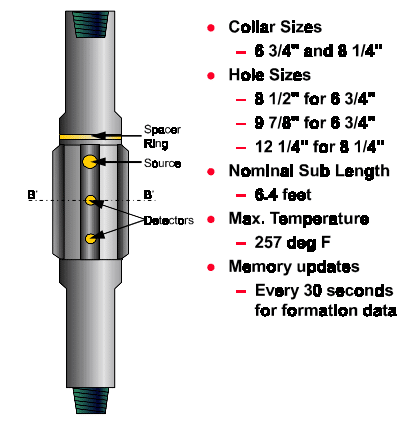
Formation Density MWD Sensors
The density tool measures the formation density by using a shielded chemical source (2 Curie, Cesium 137 source, the same as most wireline density tools) that bombards the formation with gamma rays. The formation density is a function of gamma-ray count rates (and energy level) measured at a near and far (short and long spaced) detector. The wireline counterpart of this tool is a pad contact device (containing the source and detectors) held in place by a spring-loaded, solenoid-activated caliper arm (this also provides the basic single-axis, wireline measurement of borehole diameter). It is important to minimize the thickness of mud cake between the tool and the formation in order to obtain the most accurate estimate of formation density with minimal required environmental corrections. In order to resolve this difficulty, the Teleco MDL tool achieves “pad contact” by locating the short and long-spaced MDL detectors under a full gauge drilling stabilizer. This design approximates the pad configuration of wireline density tools.