The positive displacement mud motor uses the Moineau pump principle. However, Downhole mud motors in drilling have limitations. This tool has found wide application in directional drilling and even straight-hole drilling. Drilling mud motor diagrams # 1, 2, 3 & 4 show the basic design of a positive displacement motor. This article will cover the Drilling Mud Motor Components in more detail to help you select the downhole mud motor.
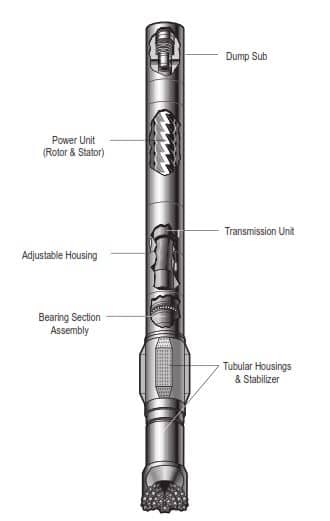
In General, The main Drilling Mud Motor Components are:
- Dump Sub
- Power Section
- Connecting Rod Assembly
- Bearing and Drive Shaft Assembly.
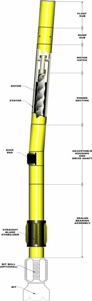
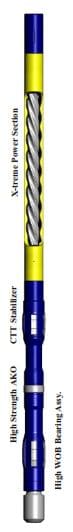
Drilling Mud Motor Diagrams
Before going in deep for the main drilling mud motor components, we have gathered some drilling mud motor diagrams to help you better understand the rest of the article.
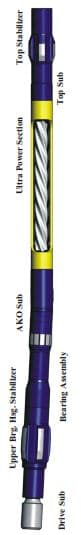
Drilling Mud Motor Components:
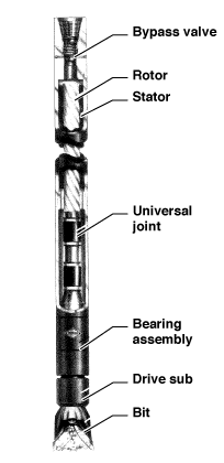
The PDM is made up of several sections:
- The bypass valve or dump sub.
- The motor section.
- The universal joint or connecting rod section.
- The bearing section with drive sub.
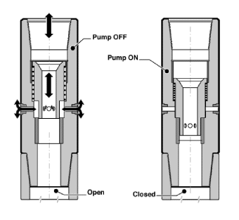
Mud Motor Dump Valve Assembly Sub:
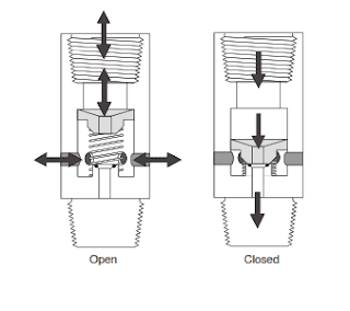
This downhole mud motor component allows the mud to fill or drain from the drill string while tripping pipe. Establishing a minimum flow rate will force the valve piston in the figure below to close the ports to the annulus. Thus, all the mud is directed through the motor. When the flow rate exceeds this minimum value, a spring returns the valve piston to the “open” position, opening the ports to the annulus.
Dump Sub can be added to the top of the power section
To avoid the ingress of solids from the annulus when the mud pumps are off (especially in loose sand), running a float sub as close to the motor as possible is standard.
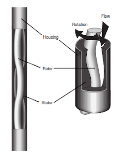
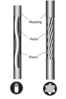
Power or Motor Section
This drilling mud motor component consists of mud motor housing, mud motor steel stator, and mud motor elastomeric rotator. The positive displacement motor is a reverse application of the Moineau pump. Fluid is pumped into the motor’s progressive cavities. The force of the fluid movement causes the shaft to rotate within the stator, as shown in the figure below. Thus, it is a positive displacement motor (PDM). The rotational force is then transmitted through the connecting rod and driveshaft to the drilling bit.
Generally, we can say that the power section converts the hydraulic fluid energy of the drilling fluid into mechanical horsepower. The mechanical horsepower of a multi-lobe rotor/stator power section is the product of high output torque and rotational speed.
Stator Configuration
The elastomeric stator is carefully bonded inside a steel tubular component, an integral component of the motor casing. The number of lobes varies from 4 to 11 through the various models in the product range. Check also Gagemaker Stator Bore Gages.
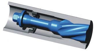
Rotor
Manufacturers produce steel rotors with matching lobe profiles and a similar helical pitch to the stator but with one less lobe. The rotor can, therefore, be matched to and inserted within the stator. The flow of the drilling fluid creates hydraulic pressure that causes the helical rotor to process and rotate within the stator.
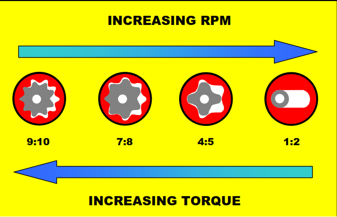
We can generally divide the drilling downhole mud motors into slow-speed, medium-speed, and high-speed types. This is done by changing the pitch of the motor stages and by the number of “lobes” and resultant cavities of the stator. In any way, the speed and torque of the resultant from the power section depend directly on the number of lobes on the rotor and stator, as per the below figure.
Note: The downhole motors will operate in either air/mist or mud. Some oil-based muds are incompatible with the rubber stator and reduce the useful life of the positive displacement motor.
Connecting Rod Assembly:
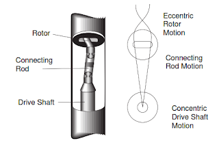
This Drilling Mud Motor Component is attached to the lower end of the rotor. It transmits the torque and rotational speed from the rotor to the driveshaft and bit. Universal joints convert the eccentric motion of the rotor into concentric motion at the drive shaft. On some models of mud motor, reinforced rubber “boots” cover the u-joints. These prevent erosion by the mud.
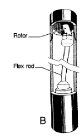
Flex rod
Another development in connecting rods has been using flexible steel or titanium flex rods. While, in general, flex rods are limited by the degree of allowable lateral bending, they have the advantage of low maintenance. This is because they do not require lubricants or rubber sleeves.
Their application has generally been limited to the low-offset steerable or straight motor. One unique approach has been to mount the flex rod inside the hollow rotor of a short, high-torque steerable PDM rather than connecting it to the bottom of the rotor. By connecting a long flex rod to the inside of the top end of the rotor and extending the flex rod through the rotor to connect to the top of the drive sub-assembly, the overall rate of the flex rod bend is decreased due to its increased length.
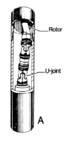
Universal Joint In Downhole Motors
The industry has conventionally utilized U-joint assemblies. We still use them in most positive displacement motors presently in the field. One major drawback may be insufficient strength for higher torque applications. Therefore, We don’t use them in recent high-torque PDMs, mainly when using PDC bits. This is due to its manufacturing process whereby the U-joint is “flame-cut,” not machined.
The assembly consists of two universal joints. Both joints are grease-filled and sealed with oil-resistant reinforced rubber sleeves. This configuration assists in protecting them from drilling fluid contamination.
A drawback of the U-joint assembly is the lack of sufficient strength for higher torque applications such as that encountered with recent generations of high torque PDMs, mainly when used with PDC bits. This inherent weakness results from the manufacturing process whereby the U-joint is “flame-cut” rather than machined.
Adjustable Assembly
Basically, the Adjustable Assembly component connects the stator to the housings of the drilling mud motor bearing Assembly and houses the Drive Shaft Assembly. We can easily set the Adjustable Assembly from straight to 3 degrees of bend angle in the field.
Bearing Assembly
The function of the bearing assembly in a positive displacement drilling motor is to support axial load (typically weight on bit) and centralize and support side loading on the motor’s driveshaft. The bearing assemblies used in mud motors have been developed for different applications, with specific motor configurations offering a choice of bearing type options.
The downhole mud motor bearing assembly consists of the following:
- Multiple thrust-bearing cartridges. The thrust bearings support the down thrust of the rotor, the hydraulic down thrust from drilling bit pressure loss, and the reactive upward thrust from the exerted weight on the bit.
- Radial bearings. We use metallic or nonmetallic radial bearings above and below the thrust bearings to protect & absorb lateral side loading of the drive shaft.
- Flow restrictor. The flow restrictor allows 5 to 8% of the circulating fluid to flow through the bearing section to cool and lubricate the mud motor bearing assembly.
The common types of Bearing Assembly that you will find in most directional drilling companies are:
- A drilling fluid-lubricated bearing is suitable for low- or medium-speed conventional motor applications requiring moderate weight on bit and drilling torque.
- High Specs Bearing features a larger internal diameter, allowing a larger diameter driveshaft and higher weight on bit. It is rapidly becoming the bearing of choice in an increasing number of applications as modern PDC drill bit designs demand higher torque,
- Diamond Bearing, the axial bearing surfaces in this design are constructed from specially designed PDCs. This design’s advantage allows the application of high-speed motors or a dramatic increase in weight on the bit on low-speed motor applications. Typical applications include hard rock drilling, requiring either high bit speed or exceptionally high WOB to deliver optimum performance.
Drive Shaft
The driveshaft is one of the mud motor components, which is a rigidly constructed hollow steel component. It is supported within the bearing housing by radial and axial thrust bearings.
This assembly connects the Power Section’s rotor & connecting rod to the rotating components of the Bearing Assembly. It can also compensate for any angle of the Adjustable Assembly or Fixed Housing and the bending subjected to the motor during directional control. The bit sub is attached to the drive shaft. When pumping through the motor, the drive shaft will turn the bit sub and the bit.
Drilling Mud Motor Rotor Catch
We generally use the Rotor Catch in down-hole Drilling Downhole Motors to ensure the extraction of the Rotor. On rare occasions, motors, mainly the power section, have parted below the Stator. When this occurs generally, the stator emerges from the hole, leaving the Rotor facing up the hole and resulting in a fishing job over an uneven surface.
Also, if the drill bit is free (also check: Pipe Sticking), it is hard to rotate over the Rotor to fish it. The Rotor catch sits at the top of the Power Section and screws directly into the Rotor. If the tool should part, the Rotor Catch will contact an internal shoulder and retrieve the Rotor.
Drilling Mud Motor Types
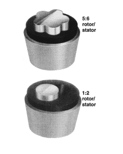
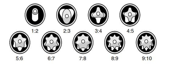
PDMs come in various configurations. As we mentioned, the stator will have one more lobe than the rotor.
- The first types of PDMs, and the simplest, are 1/2 motors. These generally give medium to low torque output and medium to high speed. Torque output is directly proportional to the pressure drop across the motor. The 1/2 motors have promising applications in performance drilling with PDC, diamond, or TSP-type bits. Some shorter models are applicable for directional drilling purposes.
- The multi-lobe downhole motors have high torque output and relatively slow speed. Therefore, they have suitable applications with roller cone bits and coring. These motors are also suitable for PDC bits, especially the large cutter types, which require an excellent torque output to be efficient. These relatively short tools also have suitable directional drilling applications with bent subs as deflection devices. These multi-lobe motors may be constructed with a hollow rotor, and a nozzle or blank will be placed in a holding device at the top. The nozzle accommodates high flow rates by bypassing the excess flow from the motor section, and the fluid will exit through the bit. The figure below illustrates a multi-lobe (5/6) positive displacement motor.
Characteristics
Torque is directly proportional to the motor differential pressure. This makes the tool very simple to operate. RPM is directly proportional to flow rate, though somewhat affected by torque output.
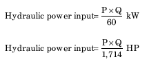
Where :
- P = the pressure drop across the motor (kPa / psi)
- Q = the flow rate (m3/min / gals/min)
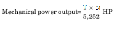
Where :
- T = the torque (Nm / lbs-ft)
- N = the bit speed (rpm)
Drilling Mud Motor Operation
Positive displacement motors were introduced in the 1960s. The first positive displacement motor (PDM) was the DynaDrill, a high-speed, low-torque motor. After we have explained downhole drilling mud motor components, we will explain the main operation in this article.
Testing & Making Up Drilling Mud Motor Operation
We should test the motor for at least three flow rates within the operating range. Record the standpipe pressure at each flow rate. High vibration may occur at specific flow rates and is common to all motors.
With the downhole motor hanging, measure the distance between the bottom of the motor housing and the top of the bit box. Then, rest the motor on the bit box and remeasure the same gap. This push-pull measurement aids in determining the condition of the thrust bearing assembly. Generally, if the difference between the two measurements is less than a 1/4” (6mm) [or 1/8” (3mm) on the smaller motors], the motor can be run.
Procedures For M/U & Testing
Here are the General procedures for Making Up Drilling Mud Motor Operation:
- Pick up the drilling mud motor, put in drilling slips, install the collar clamp, and unscrew the lifting sub.
- Test dump valve operation by hand (using a water hose and, e.g., the handle of a sledgehammer).
- If testing PDM, make up a bit first, and use x/o and Kelly / top drive. (A new PDM from the base should be OK!).
- If testing PDM with a bent sub, keep pumping time to an absolute minimum. Pick up the MWD collar. Make up the float sub & bent sub (by hand) onto the collar. Stab bent the subpin into the PDM box.
- Align the scribe line towards drawworks (or v-door).
- Pull the MWD collar over with the tugger so that bent sub-threads align with PDM box threads (i.e., horizontal).
- Put make-up tong on bent sub-body.
- Rotate the rotary table (and hence PDM) slowly counter-clockwise.
- When all threads are engaged, torque connections to API value using rig tongs. Torque all connections up to the MWD collar.
- Measure angular offset from slick pin to bent sub-scribe line. Bring up the bent sub-scribe line mark to the top of the MWD collar.
- P/U NMDC(s), UBHO (if used), and PRS. Stab into a box of MWD collars.
- Torque connections up to UBHO. Put UBHO in slips. Install collar clamp below UBHO screws.
- Back out NMDC(s).
- Align the key of the UBHO sleeve with the bent sub-scribe line. Lock in place using screws. Makeup NMDC(s) and RIH.
Running Operation
Tripping the motor should be done slowly in areas of known restrictions to prevent drill bit and motor damage. It is good practice to stage the motor into the hole, particularly in drilling environments with elevated temperatures. We can accomplish this by circulating for several minutes after every ten pipe stands or other predetermined depths. After running into the hole, flow pressure tests, similar to those performed at the surface, should be carried out with the bit turning off-bottom freely.
The pressure reading at three or four flow rates around the operating flow rate should be recorded and used for comparison in similar tests following drilling problems such as Stuck Pipe, Lost Of Circulation, well control, or any hole cleaning problem.
When tagging the bottom, apply the weight slowly and monitor the mud pump pressure changes. Initially, drilling should proceed carefully until a feel of the formation is acquired. It is necessary to feather the bit until establishing a pattern. A good drilling practice is to break the drill bit in for ten to fifteen minutes.
Procedure For Running Operations
We can use the following procedures as a guideline for downhole drilling mud motor running operation:
- The hole should be circulated clean before running PDM. Go slowly into the open hole. Driller must be careful!
- If the bottom-hole temperature (BHT) is high, break circulation periodically. If using a float valve (usually), fill the pipe regularly.
- Be especially careful near the bottom (fill, etc.).
- About one single off the bottom, P/U Kelly. Circulate. Wash slowly to the bottom. Clean the hole using the expected flow rate. Rotate slowly only if required!
- If doing a single-shot kickoff, rack back Kelly & work torque out of string before the orientation survey.
- If using MWD tool, work the pipe with pumps on (rotary locked) before taking the orientation survey.
- Orient tool face before drilling.
- For “blind” sidetrack (check also: sidetrack Drilling), orientation is not necessary. However, we must keep a tool face reference. The inclination is built along an arbitrary direction before being dropped back to vertical.
Drilling With Mud Motor
Increases in standpipe pressure are proportional to increases in drilling torque within the normal running range of the motors. Any change in torque will be due to a change in weight on bit or formation hardness. A corresponding change in standpipe pressure will reflect this.
The operational differential pressure quoted for each motor in the performance specifications tables should not be exceeded for continuous operation. Although all motors can deliver higher output torques than the continuous (operational) torque rating, the loading of the stator above the continuous rating decreases its downhole life.
When finding the optimum drilling rate, maintaining constant standpipe pressure will give steady torque at the bit and prevent erratic bit walk.
If hole conditions are suitable, we may optimize the rotary table’s penetration rate (ROP). This will keep an even weight at the bit and prevent the drill string from hanging up. Minor incremental adjustments to weight-on-bit may optimize the rate of penetration. String rotation should be limited to 80 rpm to reduce stator or thread connection damage.
A rise in the standpipe pressure will occur when tagging the bottom with a diamond bit without delivering torque due to a reduction in the cross-sectional area of the flow path around the face of the bit.
General Procedure For Drilling With Mud Motors
Below are the general procedures for downhole drilling mud motor drilling operations:
- Record off-bottom circulating pressure.
- If the standpipe pressure (SPP) is calculated and does not increase as WOB is applied, it indicates that the dump valve has not closed. Pick up off the bottom and surge the pumps. Try to force the piston to close.
- After lowering the bit to the bottom and drilling begins, torque demand on PDM increases. The pressure differential across the motor (P motor) increases in proportion. We must limit Pmotor to the value recommended for the particular motor (e.g., 360 psi for D500 Dynadrill).
- Drill with pressure gauge (WOB gauge commonly not accurate in sliding mode). Maintain a constant SPP while drilling. This ensures a steady DWOB in homogeneous formation. It should also ensure a steady tool face (provided there is no change in formation).
Downhole Drilling Mud Motor Pulling & L/D Operation
Checking the thrust bearing and stabilizer wear when the tool comes to the surface is better. We should also consider performance over the last run, total circulating hours on the tool, and bearing condition before re-running the motor. Before laying the tool down, we should flush the mud out of the power section by turning the output shaft to the right with the rotary table while holding the motor body with the break-out tools.
You can consider the following downhole drilling mud motor pulling & L/d operation:
- Use pipe spinner in open hole.
- Rotate the string slowly if necessary.
- If the dump valve ports clear, we should pull “dry”.
- The dump valve is less likely to “work” in soft formation (ports plugged with formation).
- The slug must be kept well above the dump valve when pumped.
If you don’t look after your mud motor, it won’t work for you next time! It’s a good idea to paint the number of D+C (Drilling + Circulating) hours done so far with this tool on the body of PDM. This is especially useful for your relief DD!
Things You Should Consider
- The downhole mud motor stalls will be obvious due to increased surface pressure. We should avoid motor stalling as it erodes the service life of the motor.
- Lost Circulation Material (LCM) can be pumped safely, though care should be taken that the material is added slowly and evenly dispersed and the system is not slugged.
- Solid Control In drilling is important. Keep the Sand content in the drilling fluid to a minimum using solid control equipment.
- Temperature limits are around 270°F and 130°C, but higher temperature stators have been developed.
- Pressure drop through the tool while working is typically in the range of 50 – 800 psi.
- Allowable wear on bearings is of the order of 1- 8mm, depending upon tool size.
- Flush the tool out with water before laying it down.
- In general, drilling fluids of a low aniline point may damage the rubber stator. As a rule, the oil in oil-based muds should have an aniline point of at least 150°F (60°C). Usually, this is related to the aromatic content, which should be equal to or less than 10%. Contact the local supplier if there is any doubt.
- Suppose a by-pass nozzle is fitted to a multi-lobe rotor. In that case, it must be sized very carefully to allow the motor section to develop the necessary power, and any variation of the flow for which the nozzle was inserted will compromise the motor’s performance.