We use the term ‘drilling toolface’ in connection with deflection tools or steerable motors and can express it in two ways. Physically, the place on a deflection tool, usually marked with a scribe line, is positioned to a particular orientation while drilling to determine the future course of the wellbore. Conceptually, “toolface” is a shortened term that we call “toolface orientation” at the drilling rig site. For instance, “directional drilling toolface” can be the orientation, expressed as the direction from either the Magnetic North, True North, or the topside of the hole (gravity) of the navigation sub of a steerable motor.
Toolface Orientation
In directional drilling, the drilling toolface angle measurement of the deflection tools is either up North or (Highside/Gravity).
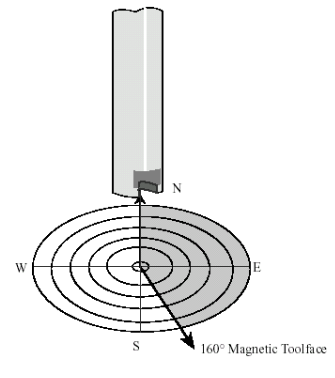
Magnetic Toolface
From vertical until approximately 5° inclination, gravity forces are minimal. A borehole does not have a well-defined high side (or low side). Up to this point, we set the toolface relative to North (e.g., N45W). We call this setting the Magnetic Toolface.
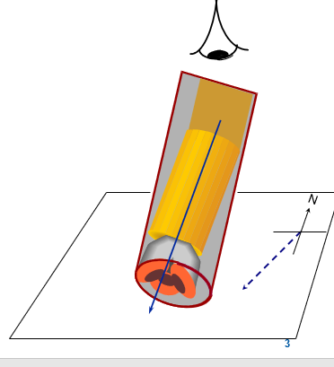
This magnetic toolface is the direction, in the horizontal plane, that indicates the orientation of the drilling toolface of a deflection tool as an angular measurement from North (direction). In other words, the direction in which the drilling mud motor bend points relative to the north reference (True or Grid).
Conclusion:
- This type is reported when the borehole has less than 3° – 5° of inclination.
- Measured as a direction on the horizontal plane
- The 3-axis magnetometer package measures the Azimuth and Magnetic Toolface.
- It may not apply to the slick motor and bent sub assemblies used at higher inclinations (over 30°) in soft or medium soft formations.
Highside or Gravity Toolface
When setting the toolface above 5° inclination, you should reference the high side of the hole. This setting is commonly called the High Side or Gravity Toolface (GTF). Precisely, the same convention applies to whether we’re using single-shot surveying tool, MWD, or Rotary Steerable Systems. Gravity forces would cause a plumb-bob suspended in the hole to hang towards the low side of the hole. The high side of the hole is 180° away from the downside of the hole.
Note: A 3-axis accelerometer package measures Inclination and Gravity Toolface Angle.
Therefore, the gravity toolface (high side) indicates whether the deflection tool orientation is facing up (0°), down (180°), or at any angle in between. Please remember that you should measure this type of orientation in a plane perpendicular to the wellbore axis.
Since the high side direction is the azimuth of the borehole, we can derive the following formula:
Gravity Toolface = Magnetic toolface – Well Azimuth
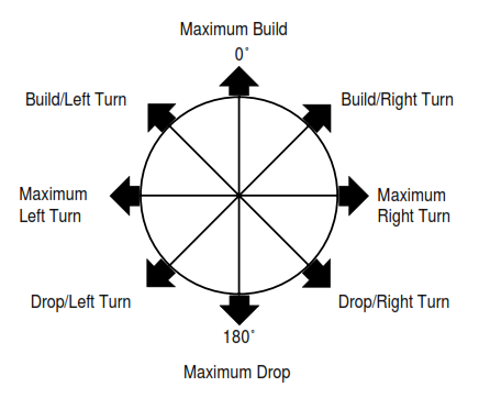
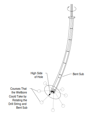
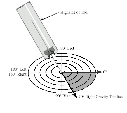
Figure 3 represents the GTF orientation. Figure 4 shows the toolface’s various positions relative to the hole’s high side. If GTF were precisely at 0° while drilling with a PDM, no change in hole direction would occur. The bent sub or bent housing dogleg capability would increase hole inclination. Conversely, no change in hole direction would occur if GTF were strictly at 180° while drilling with a PDM. To drop the hole inclination, the operator would use the bent sub dogleg capability. As an example, figure 4 is an idealized representation of GTF.
Conclusion
- The Gravity toolface in directional drilling of 0° means that the toolface is facing up to the wellbore high side.
- For the Gravity toolface of 70°, the probe’s high side point was rotated to the right of the side (check the figure below)
- The gravity toolface of 180° means that the toolface is facing down to the wellbore downside.
Rule Of Thumb Related To Toolface Orientation
We must consider some rules of thumb when dealing with toolface:
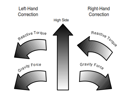
- Above 30° inclination and when using a bent sub and PDM, the hole will typically drop inclination and turn at toolface settings 60° away from the high side. At higher inclinations, this effect is even more evident.
- When turning left, the effect is most pronounced, as the reactive torque acts in the same direction as the weight of the BHA and tends to “flop over” the downhole motor (Figure 6). Therefore, taking great care when setting the toolface is essential, especially when correcting the left hand. If the tool “flops over,” a severe dogleg can result due to the hole-dropping inclination while turning left. The higher the inclination, the greater the damage that can be done. Unconsolidated formation (e.g., loose Sand) will significantly drop inclination due to hydraulic erosion.
- To achieve a “perfect” correction run, we need to POOH with the same inclination as the starting point. This means we must utilize the bent sub’s dogleg capability to turn the well. In this case, the dogleg severity achieved is the minimum possible when using these drill bit/PDM/bent sub combination. In practice, while the ideal point is rarely reached, a good DD can bring about minimal inclination change during a correction run. As a rule of thumb, it is safer to slightly build (rather than drop) inclination during a correction run. The inclination can be dropped off (if required) afterward using a rotary Bottom Hole Assembly BHA type.
- Based on the above, the directional driller should anticipate some drop in inclination at settings greater than 60° from the high side. Charts of expected reactive torque at various depths and inclinations are available from most PDM manufacturers.
What Would Make Toolface Change While Directional Drilling?
- Reactive torque changes the toolface orientation; this must be factored in when directionally drilling with a motor assembly.
- Drill string twist also affects toolface direction when drilling with a motor assembly. Twist increases with depth and will be greater with a smaller OD drill pipe.
Toolface Angle Calculation
The equations that Millheim et al. derived determine the relationships between the following parameters:
- Original hole inclination, θo
- New hole inclination, θn
- Original hole azimuth, αo
- New hole azimuth, αn
- Overall hole angle change, β
- Required toolface rotation from the original course direction, λ
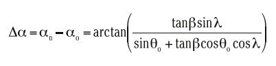
These parameters are defined by the equations below. For directional change,
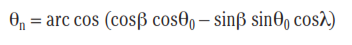
And, for a new inclination angle,
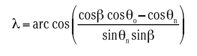
For toolface angle,
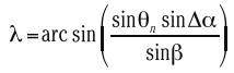
Alternatively,
Further, the dogleg severity, ψ, is defined as

Where
- L = 100 ft if dogleg severity is expressed in degrees per 100 ft
- Δd = is the length of the drilled interval between two surveys
Finally, the overall angle change is defined as

Example
Calculate the angle of toolface rotation given the following data:
| Measured Depth | Angle | Direction |
| 5000 ft | 5.5° | 150° |
| 5120 ft | 7.5° | 148° |
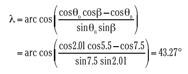
Solution:
Overall angle change is given as
β = arc cos (cos 2 sin 7.5 sin 5.5 + cos 5.5 cos 7.5) = 2.01°
With θ, β, θn all known, the toolface rotation angle is
References:
- Kim, J.; Myung, H. Development of a Novel Hybrid-Type Rotary Steerable System for Directional Drilling. IEEE Access2017, 5, 24678–24687. [Google Scholar]
- Pillay, P.; Krishnan, R. Control characteristics and speed controller design for a high performance permanent magnet synchronous motor drive. IEEE Trans. Power Electron.1990, 5, 151–159. [Google Scholar]
- Drilling Engineering Book, J.J Azar