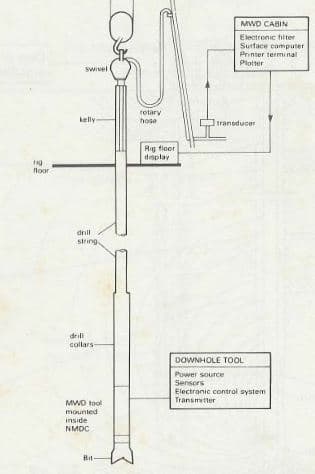
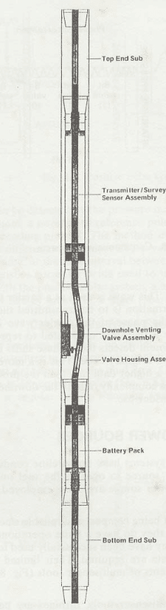
All the Measurement While Drilling MWD systems commercially available is based on some form of mud pulse telemetry. Although several different companies in oil and gas field offer MWD services, there are certain similarities among the systems being used. The major components of the MWD tools mud pulse telemetry system are shown in Fig. 1. The downhole MWD tool assembly is all housed in a nonmagnetic drill collar. This is a special collar supplied by the MWD company. Its internal diameter is greater than the regular size since it has to accommodate the MWD tool components. The major components are:
- a power source to operate the tool;
- sensors to measure the required information;
- a transmitter to send the data to surface in the form of a code;
- a microprocessor or control system to coordinate the various functions of the tool;
The control system is designed to operate the tool when information is required (e.g. when a directional survey is to be taken). To initiate the survey, the downhole tool must recognize some physical change (e.g. when drill string rotation stops or when the pumps are shut off). From this point onwards the control system powers up the sensors, stores the information that has been measured, and then activates the transmitter to send the data in the form of a coded message.
The surface equipment consists of:
- a standpipe pressure transducer to detect variations in pressure and convert these to electrical signals;
- an electronic filtering device to reduce or eliminate any interference from rig pumps or downhole motors that may also cause pressure variations;
- a surface computer to interpret the results;
- a rig-floor display to communicate the results to the driller, or plotting devices to produce continuous logs
The pressure pulses travel through the mud column at around 4000-5000 ft/s, but there are limits to the amount of information that can be sent in real-time.
Transmission Systems
The major differences between existing mud pulse telemetry systems are due to the process by which the data is transmitted. Here, we will discuss the major 3 types which are:
- Positive Pulse System
- Negative Pulse System
- Continuous Wave Systems
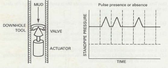
Positive Pulse System
Within the downhole tool, there is a restrictor valve that is operated by a hydraulic actuator. When the valve is operated, it forms a temporary constriction in the flow of mud through the drill string which causes an increase in the standpipe pressure. To transmit data to the surface, this valve is operated several times, creating a series of pulses that are detected by the transducer, and decoded by the surface computer. The surface computer initially recognizes a set of reference pulses, which are followed by the data pulses. The message is decoded by detecting the presence or absence of a pulse within a particular time frame. This binary code can then be translated into a decimal result. A chart recorder is used to monitor the sequence of pulses. In the event of an electrical failure in the decoding mechanism, the pulse sequence can be decoded manually from the chart recorder by the service company representative.
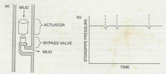
Negative Pulse System
The transmitter consists of a valve that, when opened, allows a small volume of mud to escape from the drill string into the annulus. The rapid opening and closing of this valve, therefore, creates a drop in standpipe pressure that can be detected by the pressure transducer (Fig. 3). As with the positive system, a number of reference pulses precede the data pulses to set up the decoding process. The method used to decode the message varies between different companies. The presence or absence of a pulse within a time frame, or the time interval between successive pulses, are two of the characteristics currently being used to interpret the negative pulse sequence. As with the positive pulse system, a manual interpretation of the sequence is possible by means of a chart recorder.
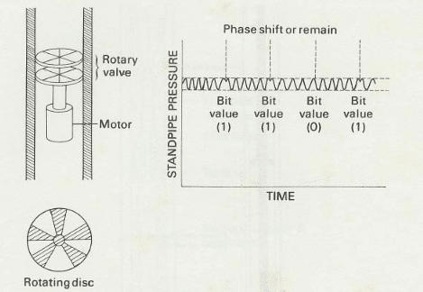
Continuous Wave Systems
Unlike the two previous methods, no distinct pulses are generated in this system. The transmitter is a rotary valve that consists of a pair of slotted discs mounted at right angles to the mudflow. One of the discs is stationary while the other is driven by a motor (Fig. 3). The constant speed of the motor creates a regular and continuous variation in pressure that is essentially a standing wave. This wave is used as a carrier to transmit the data to the surface. When information is to be transmitted the speed of the motor is reduced so that the phase of the carrier wave is altered (Le. reversed). The carrier wave is therefore modulated to represent the data required. The surface equipment detects these phase shifts in the pressure signal and translates this into a binary code. This is a more sophisticated telemetry system and offers a higher data rate than the previous two mud pulse methods. However, the complexity of both the downhole and surface components has limited its wider use.
MWD Tool Power Source Components
Since mud pulse telemetry systems have no wireline conductors running back to the surface, the power source to operate the tool must be located downhole. Two forms of power sources are being employed.
Batteries
These offer the advantage of being compact and reliable since they contain no moving parts in the MWD tool. However, they do have a finite operational life and are temperature-dependent. They have been successfully used for applications in which only directional data are required. Their limited power output does not meet the requirements of multisensor tools (Fig. 4).
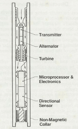
Turbine-alternator
With the trend towards multisensor tools, turbines are becoming more widely used to provide power for the MWD tool assembly. The flow of mud through the tool is harnessed by the turbine blades, which rotate a shaft connected to an alternator (Fig. 5). The electrical power generated must be controlled by a voltage regulator. Although this system provides more power and longer operating life than a battery pack, power failures can occur if the turbine is damaged. To prevent damage a screen can be installed upstream of the turbine to filter out any debris in the mud. The screen may be positioned at the top of the drill string for ease of access if it requires to be emptied or removed to allow passage of wireline tools.
MWD Tool Surface System Components
Most MWD companies use a fairly similar set of surface equipment to interpret, record and display the data measured by the downhole sensors. The amount of surface equipment will depend on the company and the number of different parameters being measured. If only directional data are required, the MWD company may only require a standpipe pressure transducer and a receiver/processing system that can be installed in the driller‘s dog house. If formation evaluation data and drilling parameters are also required, it is more practical to house all the electronic equipment and plotting devices in the mud-logging cabin or purpose-built unit located on the pipe deck. The basic components of the surface system of MWD tool are shown in Fig. 6. These are described as follows.

Standpipe Pressure Transducer
On most drilling rigs the standpipe manifold has a number of pressure taps where gauges may be installed. The transducer can be installed at a convenient point by removing one of these gauges. Inside the transducer is a sensitive diaphragm that detects variation in pressure and converts these hydraulic pulses to electrical voltage pulses. The voltage output is relayed to the rest of the surface equipment by means of an electric cable.
Electronic Filters-Amplifiers-Surface Computer
As well as detecting the MWD pulses, the transducer will also respond to pressure variations caused by the rig pumps or downhole motors. This background noise makes it difficult to identify the MWD pulses. It is sometimes possible to alter the speed of the rig pumps to reduce this interference. Pulsation dampeners on the rig pumps should prevent any large variations in discharge pressure.
The signal from the transducer can be improved by filtering out these unwanted pressure fluctuations. With the expected frequency of the MWD signal known, the electronic filters can be set to eliminate any other frequencies above or below this pre-set range. The signal can then be further enhanced by amplifying it to show the distinctive peaks or troughs. The enhanced sequence of pulses is then fed into the surface computer which is programmed to recognize the reference pulses and then decode the data pulses. The final results are listed on a print-out at the computer terminal and recorded on magnetic tape.
Directional results (azimuth, toolface, and inclination) are relayed to the rig floor where they are displayed on a panel for the convenience of the directional driller. Formation evaluation data are printed out continuously as drilling proceeds. A depth-tracking system must also be used to plot gamma-ray or resistivity response against depth.
Directional data, formation data, and downhole drilling parameters are transmitted in a pre-determined sequence. The sequence and frequency of the measurements vary with different manufacturers and also depend on how the tool is being operated. For example during a steering run only survey data may be transmitted; during rotary drilling gamma-ray and resistivity may be transmitted.