In general, the neutral point can be defined as the point in the drill string where there is a change from tension to compression in the axial stress or the point that is zero tension and zero compression. The location of this neutral point depends on WOB and the Bf buoyancy factor (that depends on the drilling fluid). In practice, the neutral point changes its place as there is a fluctuation in the WOB. For this reason, we call the section of the axial stress that keeps changing from tension to compression a “transition zone”. Our objective in this article is to explain the neutral point definition to drilling engineers and calculate the neutral point’s approximate location in a rotary drill string via different formulas.

The neutral point divides the drillstring into two parts. The upper part, with length X 1 , is in effective tension, and the lower part, with length X , is in effective compression.
Fundementals of drilling engineering book
Drilling string components in the “transition zone” may, therefore, alternately experience compression and tension. These cyclic changes can hurt these tools. An excellent example is the drilling jars, whose life may be dramatically trimmed if the jars are found in the transition zone. It is also essential, as previously explained, to know if any drill pipe is being run in compression. Thus, it is critical to know the location of the neutral point and redesign your BHA to move any critical components out of the transition zone.
To reduce the drill collar buckling tendency, it is aimed to do drill string design in such a way that the neutral point is located inside D/Cs. This design criterion is often used to evaluate the length of required collars.
Drilling Engineering Dipl.-Ing. Wolfgang F. Prassl Curtin University of Technology
Calculation of Neutral Point In Drilling
Neutral point calculation formulas in drill string have four cases depending on the well profile and the position of a neutral point that are as follows:
- In drill collars for vertical wells.
- In heavy-weight drill pipes for Vertical Wells.
- In drill collars for deviated wells.
- In Heavy weight drill pipe for deviated wells.
Neutral Point Formulas In Drilling String
The Drill Collars In Vertical Wells
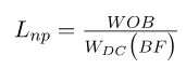
Where:
- Lnp: the length from the drilling bit to the neutral point.
- BF: the buoyancy factor
- WDC: the weight per foot of the drill collars
For HWDP In Vertical Wells
Here, we assume that there are D/Cs & HWDP in the bottom hole assembly. In this situation, performing the neutral point calculations may be more difficult. But it will be easier to do the following steps:
- Check from the previous neutral point formula if it is in the drill collar
- If Lnp is less than the length of the D/Cs, then the neutral point position is within the D/Cs
- If Lnp is more than the length of the D/Cs, use the following formula to locate it in HWDP
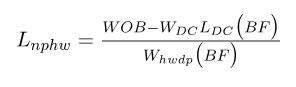
Where:
- Lnphw: the length from the bottom of HWDP t to the neutral point
- WOB: the weight on the bit
- WDC: the weight per foot of the collars
- LDC: The total length of the drill collars
- Whwdp: the weight per foot of the heavyweight
- BF: The Buoyancy Factor
For The Drill Collars In Deviated Wells
When the neutral point is in the D/Cs section, assuming that they have a similar diameter, the following formula shall be used:
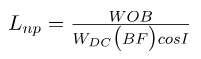
Where:
- Lnp: the length from the drilling bit to a neutral point in feet
- WDC: the weight per foot of the drill collars
- BF: The Buoyancy Factor
- WOB: the weight on the bit
- I: the wellbore inclination angle
For HWDP In Vertical Wells
Similar steps will be performed to check if the neutral point is in the D/Cs or the HWDP. If the neutral point is confirmed to be in the HWDP and all the drill collars are of the same diameter, the following formula should be used:
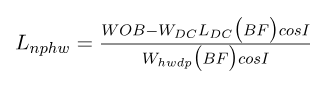
Where:
- Lnphw: the length from the bottom of the Heavy-weight drill pipe to the neutral point.
- LDC: the total length of the drill collar section.
- Whwdp: the weight per foot of the HWDP
General Drilling Formula for Neutral Point in Deviated Wells
The last formula can be expanded in the case of a “tapered” bottom hole assembly with drill collars of more than one diameter. For example, if there were two drill collar sizes and the neutral point located in the HWDP, the formula would become:
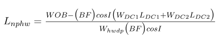
Where:
- WDC1: the weight per foot of the 1st size of drill collar
- LDC1: is the weight per foot of the 1st size of drill collar
- WDC2: the weight per foot of the 2nd size of drill collar
- LDC2: is the weight per foot of the 2nd size of drill collar
References:
- Schlumberger – Drill String Design Manual
- Petroleum Engineering Handbook
- Drilling Data Handbook