Drilling jars are one of the BHA components that should be run with the drill string to help free stuck pipes. There are two common types of drilling jars: hydraulic and mechanical. Hydraulic jars use the pressure the string generates to apply an impact load. In contrast, the mechanical type uses a spring-loaded design to create an impact load. This tool selection is an essential step in drill string design. This article will discuss the working principle, placement, types, operations, and calculations involved in using drilling jars.
National Oilwell Varco is one of the leading suppliers of such tool. Their range of products, which includes the Jar Impact, features multiple sizes and configurations for deep-hole applications such as offshore wells and directional jobs. BICO Drilling Tools, Inc., Cougar Drilling Solutions, Odfjell Drilling, and Pacific Drilling are significant players in the drilling jar market.
What Is The Jar In Drilling?
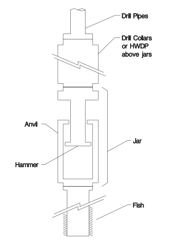
Drilling jars are run as part of most directional bottom-hole assemblies. Depending on the operations, jars may or may not be run on vertical wells. The jars’ design allows delivering an impact in either an upward or a downward direction. Some jars work in one direction only. Inside, a jar is basically a sliding mandrel that allows a brief and sudden axial acceleration of the string above the jar. Travel of this mandrel (the hammer) is limited by a stop (anvil) on the outer sleeve.
When We Start Thinking About Using Drilling Jar
In general, the purpose of drilling jars placement in the BHA is to generate upward or downward impact loads to free a stuck pipe or release a fish. Many factors affect when to use jars and where to position them for maximum benefit.
Nowadays, every string run in a hole uses a drilling jar, whatever its type. But they are mainly required in the following situations:
- There are sloughing formations in a given area or at a particular depth.
- There are sensitive swelling shales.
- The Circulating System used does not have good suspension properties to suspend cuttings.
- There is costly equipment in any type of bottom hole assembly, such as a monel Drill Collar, downhole motor, or Measurement While Drilling tools that need to be recovered.
Drilling Jars Types
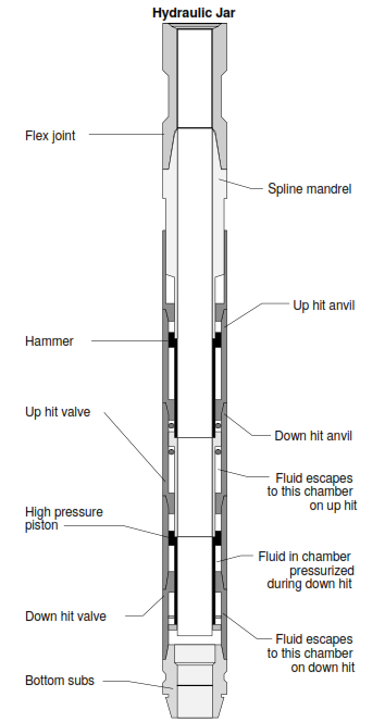
Hydraulic Jars Working Principle
The most common type of hydraulic drilling jar type working principle operates on a time delay sequence wherein hydraulic fluid is metered through a small opening for the initial extension of the mandrel. After moving a small distance over several minutes, the fluid opening size increases dramatically, and the jar opens unrestrained. Finally, when the jar has reached the end of its stroke, a tremendous jolt is achieved by rapidly decelerating the collars and Drill Pipe above the jars that had built speed during the unrestrained portion of the opening cycle.
The magnitude of the jar’s impact depends on the Tension applied to the jars when fired. The time required for a hydraulic jar to fire depends on the following:
- The type of hydraulic fluid used
- The size of the metering hole
- The temperature of the hole.
Repeated firing of jars generally increases the hydraulic fluid temperature and, therefore, lowers the viscosity of the fluid and the time required for firing to occur to a point where the jar becomes useless.
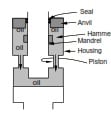
Mechanism
We can explain the hydraulic jar working principle using this schematic diagram. When pulling the drill string, the piston moves up inside the housing and forces the hydraulic oil to move down through the small annular clearance between the piston and the housing. Therefore, it restrains the movement of the piston. It takes several minutes for the piston to move out of the small-diameter housing. Once the piston moves into the larger ID area, the piston velocity increases dramatically. In addition, when the hammer hits the anvil, a tremendous jolt is achieved. The magnitude of the impact is directly proportional to the amount of tensile pull applied to the jars before firing.
We can determine the hydraulic jar working principle for firing delay by a combination of load applied and time. Do not exceed the manufacturer’s recommended maximum jarring load; exceed the fishing tools’ tensile strength or work string.
Working Principle Of Mechanical Drilling Jar Type
Another common type of jar is a mechanically operated one. Mechanical Jars Working Principle is to preset jar at the surface or in the shop to fire at a given tension. Mechanical jars use a detent device to delay the firing of the jar until the stretch is to the work string. We can define the detent as a device such as a catch, dog, or spring-operated ball to position and hold one mechanical part about another. Therefore, the device can be released by force applied to one of the parts.
One major advantage of mechanical jars is that they will not fire until the threshold setting is reached. They are often perceived as being more rugged and durable than hydraulic jars.
Drilling Jar Operations
In the Jarring Operations & Procedure Article, we shall discuss the following subjects:
- Jar Safety Clamp
- Picking Up The Jar
- Establishing the Jar Load
- Changing the Jar Load
- Changing the Jar Cycle
- Up-Jarring Operation
- Down-Jarring Operation
- Up And Down Jarring Operations
- Setting The Drilling Jar Prematurely
- Coming Out Of The Hole
Drilling Jar Calculations
Jar Open Force Calculations
The jar pump open force (POF) (also called jar extension force) is the difference in hydrostatic pressure between the external (wellbore) and internal (drill string) pressures. This differential pressure results from the exposed internal/external surface areas. When a differential pressure exists between the inside of the jar (higher pressure) and the outside (lower pressure), it produces a resultant force that opens the jar. This differential pressure is present under normal circulating conditions due to the pressure drop across the drill string MWD, Motor, and Bit, plus any annular pressure drops from the bit up to the jar.
A differential pressure will also exist if trapping pressure inside the string, and there is no trapped pressure in the annulus at the jar. This occurs when there is a string pack off below the jars, and pressure cannot bleed off at the standpipe. The effect of pump open force on jarring can be considerable. For example, if 2000 psi is trapped inside the jar when the string is packed off below the jar, the pump open force can be as high as 60000 lbs, depending on the jar size and type used. Its manufacturer will provide the pump open force charts.
Drilling Jar Force Calculations Formulas
Jar Calculations Formula for calculating the surface weight that we require to fire the jar up (once cocking it). Apply a measured weight of at least Uj.
Uj = UpWt – BHA Wt below Jars – POF + Jar up trip force
Drilling Jar Calculations Formula for calculating the surface weight that we require to start cocking the jar to enable us to fire it up. Setdown to at least a measured weight of Uc (we may need more).
Uc = DnWt – BHA Wt below Jars – POF – Jar fric
Drilling Jar Calculations Formula for calculating the surface weight that we need to fire the jar down (once cocking it). Setdown to at least a measured weight of Dj.
Dj = DnWt – BHA Wt below Jars – POF – Jar Dn trip force
Drilling Jar Calculations Formula for calculating the surface weight required to start cocking the jar to enable us to fire it down. Apply a measured weight of at least Dc.
Dc = UpWt – BHA Wt below Jars – POF + jar fric
Notes
- NB1: In a non-vertical well, BHA.Wt.below.jars = BHA.Wt.below.jars x cos (Inclination).
- NB2: trip force = the force (Tension or compression) at the jar we use to fire it.
- NB3: Jar friction is usually about 5000 lbs. We ignored it for the firing stroke but included it in the calculation for the cocking stroke.
These Drilling Jar Calculations provide approximations of the actual surface forces required.
Positioning & The Drilling Jar Placement In BHA:
To be of most benefit, drilling jar placement in the Bottom Hole Assembly BHA should be a small distance above the point where sticking is likely to occur. If the jars are placed far above the stuck point, some jarring action is wasted in stretching the pipe between the jars and the stuck point. Jars are rendered useless if stuck or placed below the stuck point.
Prediction of the stuck point (also check free point calculation for stuck pipe) is not straightforward. It depends on the types of formations drilled, wellbore conditions, and the driller’s experience in the area.
For example, suppose a BHA with three Stabilizers is used to drill sloughing shale. In that case, the shale will likely slough and pack around all three stabilizers. In this case, the jars are often placed above the top stabilizer. Usually, a few drill collars are placed above the jars to achieve effective jarring force on the collars below the jars.
All drill collars could become a stuck pipe problem if differential sticking is likely. In this case, placing the jars in the Heavy Weight Drill Pipe HWDP above the collars would be advantageous.
The two primary considerations for jar placement are preventing jar fatigue failure and maximizing jar impact at the probable sticking location.
In the olden days, when holes were near-vertical, the “rule of thumb” was to make drilling jars placement in “tension .”In other words, place it above the buckling neutral point. More recently, jar companies said running jars in “compression” is acceptable. In other words, we can place it below the neutral point but not at the “neutral point” itself. This is under the misconception that the Tension = 0 at the neutral point.
Fatigue Failure Prevention
To simplify matters, we should apply the rule: Don’t run jars buckled at any time. This rule prohibits drilling jar placement below the neutral point in vertical or near-vertical hole sections.
The compressive load a jar may carry without buckling in high-angle holes will depend on many factors. In addition, we can easily estimate using jar dimensions and the Dawson-Pasley relationship for drill pipe buckling. Regarding the prohibition against running jars in the “neutral point,” this will not always be practical in high-angle holes.
For example, in the recent North Sea extended reach well, with a hole inclination of 75 degrees, bit weights varied between 5,000 and 25,000 lbs. as stringers were drilled. Limiting the ROP to clean the hole was necessary for the soft formations, thus the lower bit weight. The higher bit weight was required to drill the more complex rock. The upshot was that the “neutral point” constantly moved over a range of about 1,800 feet in the string (and past the jars).
Although the jars may have cycled from open to closed, the change in position occurred at low energy levels because care was taken not to add a bit of weight too fast, and no problem occurred with the jars. Suppose you expect a situation like the one above. In that case, you should discuss the circumstances with your jar company. This will help develop operating limits to prevent cycling the jar while storing too much energy in the drill string.
Maximizing Jar Impact
We usually don’t know where the string will become stuck beforehand, so the drilling jar placement is traditionally positioned to give the highest average freeing force along with the BHA. We can do the jar placement calculation with the help of computer simulation. In addition, for many drill string and borehole configurations, there will be one drill collar below the top of the BHA.
Hammer & Anvil
This is similar to envisioning a hammer and an anvil. The mass of the hammer is the single drill collar above the jar. The anvil is, of course, the rest of the BHA. For upward jarring, the energy for jarring is temporarily stored as elastic stretch in the pipe, then suddenly released as the jar trips. The opposite applies for downward jarring, as the jar temporarily supports, then suddenly releases weight slacked off from the surface. For upward jarring at a given string stretch, the mass of the drill collars above the jar will affect the jarring impact.
So, drilling jar placement and its impact are related to too much drill collar mass above the jar, and the collars will not gain sufficient speed by the end of the jar travel to hit with the desired force. Also, too little and the blow may be insufficient because of inadequate mass coming to an abrupt stop at the end of jar travel.
Drilling Accelerators
If the risk of a stuck pipe problem is very high, there will be a need to use a drilling accelerator. A drilling accelerator is a spring element that provides the energy for the jar’s impact after it trips, thus replacing some of the functions of the drill pipe stretch. This can be more effective because the accelerator is less affected by borehole friction than the drill pipe and has a more favorable dynamic force/displacement characteristic. We generally place the drilling jar accelerator between the HWDP and the top drill collar.