Before going in deep into its components, we can define the Drilling rig as a complex of equipment and tools that is used in:
- DRILLING
- RE-DRILL OR RE-ENTRIES
- WORKOVERS
Drilling Rig Equipment Systems Components
There are 4 main systems on a drilling rig:
- HOISTING & ROTATION SYSTEM
- POWER GENERATION SYSTEM
- MUD CIRCULATING SYSTEM
- WELL CONTROL SYSTEM
HOISTING & ROTATION SYSTEM COMPONENTS IN DRILLING RIGS
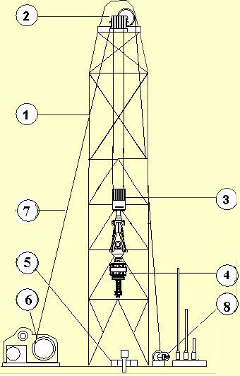
- MAST & SUBSTRUCTURE
- CROWN BLOCK
- TRAVELING BLOCK
- TOP DRIVE
- ROTARY TABLE
- DRAWWORKS
- DRILLING LINE
- DEADLINE ANCHOR
POWER GENERATION SYSTEM
Ac-Dc Power Generation Station Example:
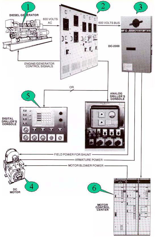
- GENERATORS
- CONTROL PANELS
- TRANSFORMER
- DC MOTOR
- DIGITAL DRILLER CONSOLE
- MOTOR CONTROL CENTER
MUD CIRCULATING SYSTEM COMPONENTS IN DRILLING RIGS
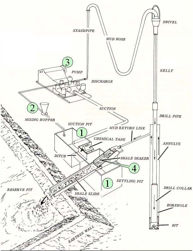
- MUD PITS
- MUD MIXING HOPPER
- MUD PUMPS (HI AND LOW PRESSURE)
- SHAKERS
WELL CONTROL SYSTEM
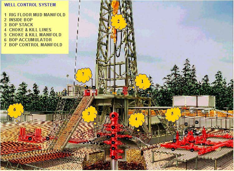
- RIG FLOOR MUD MANIFOLD
- INSIDE BOP
- BOP STACK
- CHOKE & KILL LINES
- CHOKE & KILL MANIFOLD
- BOP ACCUMULATOR
- BOP CONTROL MANIFOLD
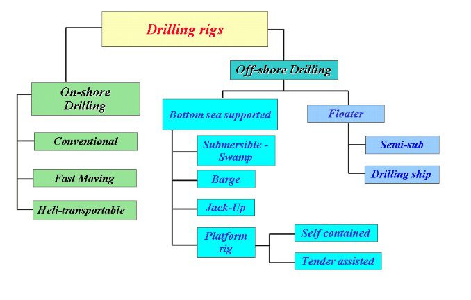
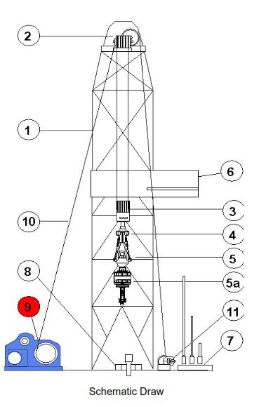
Drilling Rig Components
Derricks
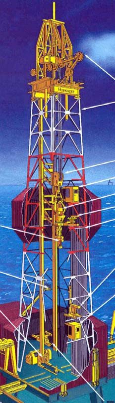
Drilling derricks and Rig Masts consist of a steel framework with a square or rectangular cross-section. Their purpose is to support the hoisting equipment and rack the tubulars while tripping pipe.
The number of joints in a stand (single-double-triple) that the rig can pull is dependent on the height of the derrick.
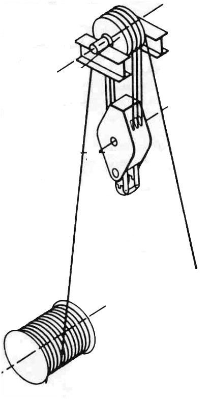
Drawworks
The Drawworks is one of the most important components of the drilling rig (types of drilling rigs). The unit supplies the hoisting power, the drawworks spools the drilling line as the drill pipe is run into and pulled out from the well. The drilling line spools out under gravity and is reeled in by an electrical or diesel engine.
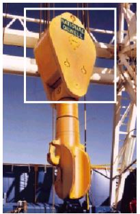
Crown Block
The Crown Block as a drilling rig component is a fixed set of pulleys (called sheaves) located at the top of the derrick or mast, where the drilling line is threaded. The companion blocks to these pulleys are the traveling blocks. By using two sets of blocks in this fashion, great mechanical advantage is gained, enabling the use of a relatively small drilling line to hoist loads many times heavier than the cable could support as a single strand.
Traveling Block
The Traveling Block is a set of sheaves (pulleys) that move up and down in the derrick. The drilling line is threaded (reeved) over the sheaves on the crown and through the sheaves in the traveling block. This provides a great mechanical advantage to the drilling line, enabling it to lift heavy loads of pipe and casing. The number of the pulleys used on the two Blocks can vary from 5 to 8, providing a variable capacity for the Hoisting system.
Hook
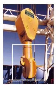
Attached to the bottom of the traveling blocks, the hook is required to hang the swivel and rig kelly (for drilling) and the elevator bales (for tripping pipe and casing).
Drilling Line
The factors to consider in the drilling line choice are:
- Diameter
- Breaking strength
- Flexibility
- Elasticity
- Corrosion strength
- Abrasion resistance
- Distortion strength
The drilling line shall be in compliance with: API 9A and API RP 9B.
Rotary Table
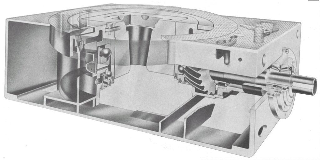
Before the TOP DRIVE SYSTEM component introduction, the drilling rig rotary table had two main functions:
- Transmit rotation to the BHA through the Kelly Bushing.
- Collect and support the weight of all the tools to RIH.
With the invention of the TOP DRIVE, the rotary table is only used for the second function.
Kelly & Drive Bushing
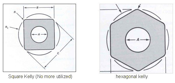
The function of the Kelly is to transmit rotation and torque to the drilling bottom hole assembly.
Types:
Kellys are manufactured as square or hexagonal.
- Hexagonal kelly
- Square kellY
Kelly Valves
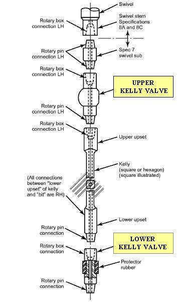
Kelly valves are manually operated valves that run above and below the kelly to shut off back-flow in the drill stem in the case of a well kicks (check also Kick warning signs). – Upper Kelly Cock – Lower Kelly Cock The valves are manually operated with a dedicated wrench. This is a limit for quick intervention. The Top drive system has eliminated this with remove control operated valves.
Swivel Head
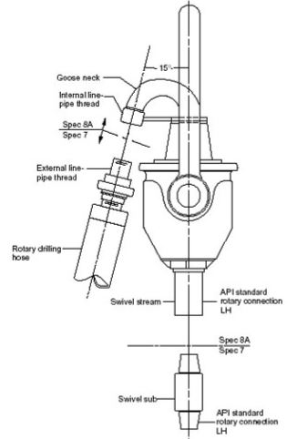
The Swivel head has 3 main functions:
- Bears the drill string load
- Enables string and bottom hole assembly rotation
- Allows circulation
Top Drive
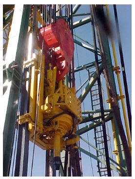
Oil well drilling rigs with a rotary table component, Kelly drive bushing, and 45 ft of Kelly were the industry standard for years. TOP DRIVE is a drilling rig equipment that has been one of the better innovations in the oil field in the last few years. The top drive system has three main functions:
- Perform all normal hoisting requirements
- Rotate the drill string
- Enable circulation through the drill string
Most rigs today are equipped with the top drive.
Advantages:
- Possibility to drill stands of drill pipe rather than single
- Ability to back-ream while pooh
- Contains remote-controlled Inside BOP, that can be operated at distance from the rig floor
Manufacture specifications
- Top Drive is built in accordance with API Spec. 8A and 8C.
- The reference standard adopted by the most international companies is: ISO 13535
Read more on Top Drive in Drilling Components, Pros & Maintenance Steps
Drilling Rig Floor Mud Manifold Equipment
The mud manifold is composed of pipes and valves. It connects the high-pressure mud pumps to the injection head in order to circulate the drilling mud down the DP. There are several outlets on the mud manifold to connect the pressure transducer. This allows the crew to monitor the “stand pipe pressure“
Types:
- Single Stand Pipe
- Dual Stand Pipe
Mud Pumps
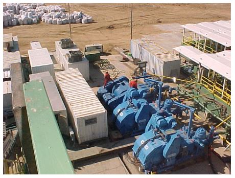
Duplex Pump / Triplex pump Hi-pressure mud pumps:
- In a drilling rig Duplex Pump, the piston component discharges mud on one side of the piston and at the same time takes mud in on another side.
- In a Triplex pump, the piston discharges mud only when it moves forward in the liner. In the Oilfield, duplex pumps have been replaced by triplex pumps. Triplex pumps of the same power, are smaller and lighter than duplex pumps. They also provide a uniform flow.
Pistons are moved with a shaft by an electrical engine or a diesel engine.
The pump is divided into 2 parts:
- POWER END
- FLUID END
Read more on Mud Pump In Oilfield Rigs Parts, Types & Calculations
Mud Mixing System:
The mud mixing equipment is used to accomplish the following:
- Prepare and mix the mud.
- Maintain mud weight (check also Mud balance test procedure) and mud properties while drilling the well.
Mud mixing must be done at the highest pump rate, to avoid decantation and grumes of the solid part (barite in drilling, bentonite, polymers, etc).
NOTE: event of a kick: The mud mixing system must enable personnel to mix as much mud as required, as fast as possible, in the event of a kick (check also kick tolerance – Kick sheet calculations).
The mud mixing system includes:
- Centrifugal pumps
- Funnel with nozzle and Venturi pipe
- Charging hopper
Mud Pits
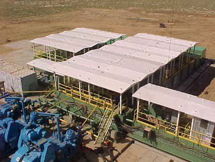
The Mud Pit enables the rig crew to:
- Contain the drilling mud in a close system
- Monitor the physical and rheological characteristics of the mud
- Monitor the well lost circulation with lost circulation material
- Control kicks – killing methods (wait and weight – Driller’s method)
- Mud Pits Capability
The capability of the mud pits depends on:
- Formations and characteristics
- Applicable laws at the operation zones
- Well’s depth
- Logistic positioning and well site.
There are 2 categories of mud pits:
- Active Mud Pit System
- Supply Mud Pit System
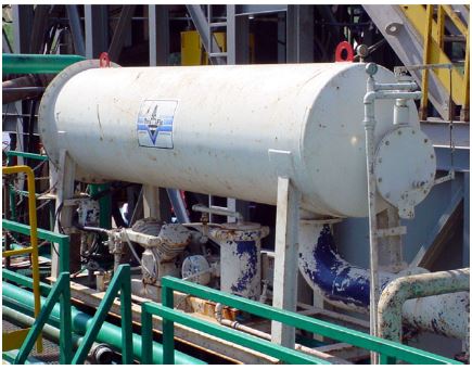
Trip Tank Component In Drilling Rigs
For monitoring of the mud – It is necessary to monitor the amount of mud that exits or enters the hole as the drilling string is run in or out. The monitoring, or measurement, can be done either by using the rig pumps and calculating the number of strokes required to fill the hole or by using a trip tank.
A TRIP TANK is any pit or tank in which the mud volume can be measured accurately to within +/- 1.0 bbls. As the pipe trips out from the hole, the mud from the tank is allowed to fill the hole as needed, which at the same time denotes the amount of mud being used.
The mud fills the hole by a pump with a return line from the bell nipple to the tank. A continuous fill up device doesn’t require as much of the driller’s attention.
Components
Trip tank used on every rig has:
- pit
- centrifugal pump
- pit level.
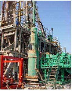
Solids Removal Equipment in Drilling Rig
A large number of solids in the mud can cause many problems during drilling. It also results in
high mud treatment costs trying to maintain the shape of the mud. The purpose of solid removal equipment is to contain the percentage of solids in the mud at an acceptable level.
The benefits of a low solids content are:
- Higher rate of penetration during drilling (check: Drilling Parameters Optimization In Oil & Gas Guide)
- Increased bit life (Learn more about: Bit dull grading)
- Reduced mud control costs
- Reduced mud pump maintenance costs
- Reduced possibility of stuck pipe
- More regular hole geometry
- Reduced need for mud dilution
- Increased cement efficiency
- Reduced BHA torque (check also drilling torque and drag)
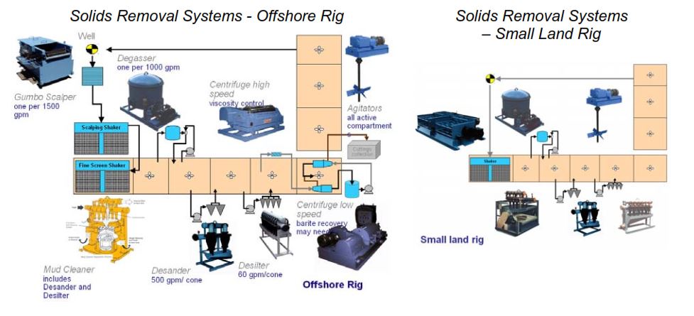
- Solids control equipment
Solids control equipment as a component used on a Drilling Rigs include:
- SHALE SHAKER
- DESANDER & DESILTER
- MUD CLEANER
- DECANTER CENTRIFUGE
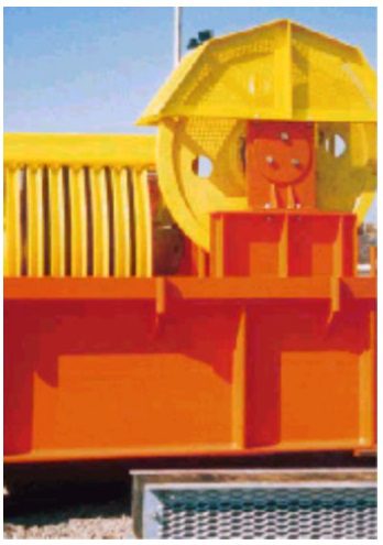
Degasser
The purpose of degassers is to remove air or gas entrained in the mud system in order to ensure that the proper density mud is recirculated down the drill pipe. If the gas or air is not removed, the mud weight measured in the pits may be misleading. This will result in the addition of unnecessary amounts of weight material thereby giving true mud densities down the hole that are more than desired. Gas contamination could result from:
- Drilling Gas.
- Trip Gas.
- Connection Gas.
- Well testing.
All degasser types operate on turbulence and vacuum.
- VACUUM: The vacuum increases gas speed through the vertical vent line.
- TURBULENCE: Mud flows in thin sheets over a series of baffles arranged inside a vertical tank. The resulting turbulent flow breaks out large gas bubbles which then rise through a vent line.
Drill Pipe Component in Drilling Rigs
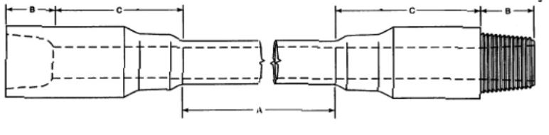
A joint of drill pipe is composed of 2 parts: the body and the tool joint.
- Body: central part – API 5D specifies the dimensions and characteristics of the body.
- Tool Joint: connections welded to each end of the pipe body and threaded – one box thread
and one pin thread. API 7 specifies the dimensions and characteristics of the tool joint
The ISO reference is the draft 11961
Read more on Drill Pipe API Specifications
Heavy Weight Drill Pipe
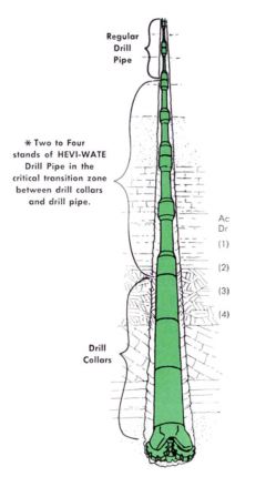
As a component of the Drilling rig String, Heavy weight Drill pipe has a unit weight between Drill Pipe and Drill Collars. They are run between Drill Collars and Drill Pipes to:
- Create a gradual reduction of BHA rigidity (check BHA types) between the two.
- Reduce fatigue stress on the DP just above the DCs.
- Reduce wall friction in vertical deep wells with high RPM.
HW DP dimensions are standardized by API 7. The relevant ISO standard is the 10407 Spec.
Benefits:
- HW Saves Rig Time by Reducing Trip Time
- HWs stand back in the rack like regular Drill Pipe
- Reducing wall friction In Deviated Well: Reducing wall friction in deviated wells, heavy wall DP gives better direction control in deviated wells.
Drill Collars
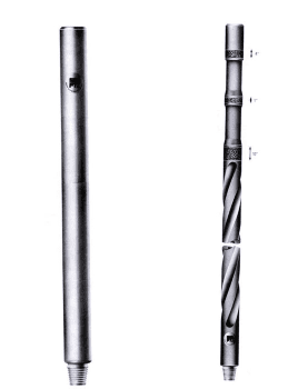
Drill collars are the components of the drill string (check also Drill string Design Calculations) that provide the weight on the bit when drilling (drill string weight calculations). They are thick-walled, hollow tubular machined from solid bars of steel (usually plain carbon) or non-magnetic nickel-copper alloy or other non-magnetic premium alloys. The outside diameter may be machined with helical grooves (spiral) to reduce the potential contact surface for differential sticking prevention.
Drill Collars dimensions are standardized by API 7 Specifications. The ISO 10407 Spec. is actually a draft.
DRILL COLLAR TYPES
- Smooth
- Spiral
Pipe Handling Tools
Elevator Links
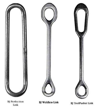
The elevator links provide the connection between the hook (or Top drive) and the elevator.
There are 3 different types of links:
- Perfection Link
- Weldless Link
- Tool Pusher Link
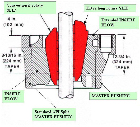
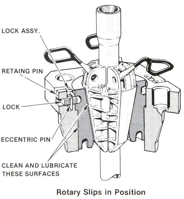
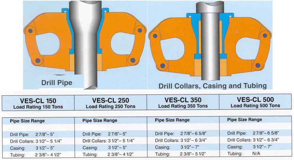
Manual Slips
According to API 7K standards, slips are tapered 4 inches per ft on the diameter.
- Manual Slips for Drill Pipe
- Manual Slips for Drill Collars
- Manual Slips For Casing
- Manual Slips for Conductor Pipe
- Safety Clamp
- Automatic slips mechanically released
- Remote controlled Automatic slips
Elevators
- ELEVATORS for DP – DC Manual: These elevators have replaceable bushings to fit different sizes of pipe.
- DC Lifting Sub: Most contractors have decided, for safety reasons, not to use elevators for drill collars with upsets. Due to drilling wear, the elevator contact area on the collar is decreased and can become very dangerous. Instead, contractors prefer to use DC lifting subs. They add to trip time but significantly increase safety.
- ELEVATORS for DP – DC Remoted controlled
- ELEVATORS for Casing: Special elevators are used for running casing procedures.
- Side Door Elevators: These are used for lightweights or for the first joints of csg.
- Slip type elevator:
- Slip type: Operated manually or by remote control, these can be used as elevators or clamps.
- Ton Elevator: Ton Elevator / Spide Varco Type: Size range from 2 3/ 8″ up to 24 ” for 200 ton to 1000 ton
- SINGLE JOINT ELEVATORS
Tongs
DP and DC make-up occurs in two stages:
- Spin the two tool joints together (spinning)
- Torque connection to tighten it (Make-up torque) Viceversa for Breakdown operations.
For DP and DC make up torque values are indicated in API RG 7G. Two tongs are used and positioned on the 2 tool joints. The top one is for the torque and the bottom one as a backup tong.
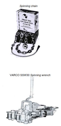
Spinning chain
Spinning was historically done with the spinning chain, but this was dangerous and the safety of all on the drill floor depended on the skill and experience of the man throwing the chain.
Spinning wrench
The automatic spinning wrench is now replacing the spinning chain in many drilling rigs.
TONGS for DP – DC & CASING Manual
Operational Two tongs are used and positioned on the 2 tool joints. The top one is for the torque and the bottom one is a backup tong.
Torque is applied by pulling the top tong with the cathead. For high torques a hydraulic piston is used for pulling (Ezy Torque).
- Torque applied: Torque applied is the result of the pull multiplied by the tong arm length.
- Torque Indicator: The pull should be applied as perpendicularly as possible to the arm to avoid false values.
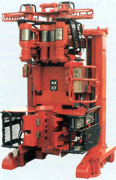
TONGS for DP – DC & CASING Automatic
DP torque Wrench: Making up and breaking out made simple. The hydraulically powered TW-60 makes up and breaks out drill pipe tool joints and drill collars from 4 to 8 inch OD. Torque is adjustable and can be pre-set to the required value.
SPINNING & TORQUE Combination Wrench
- Tongs for DP – DC Automatic
- Tongs for CSG Automatic
PIPE RACK
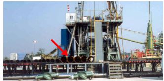
The pipe rack is the place where tubular are stored and positioned before lifting them up the rig floor. In the photo shows Casings already equipped with centralizers all ready to be run in the well.
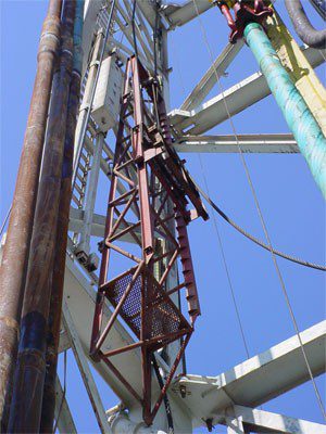
FINGERBOARD
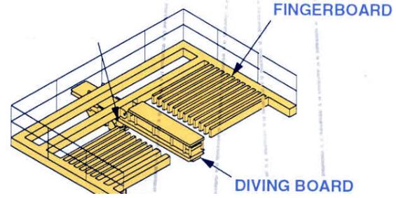
The Fingerboard is one of the drilling rig components that is used to rack the tubular while tripping.
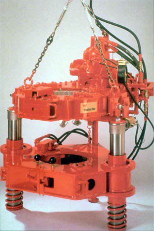
PICK UP & LAY DOWN MACHINE
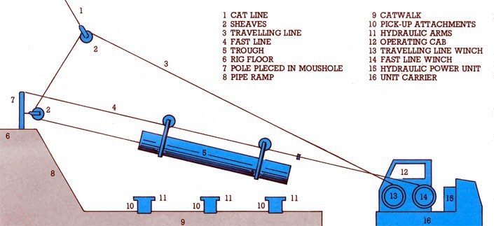
The pickup and lay down machine was designed to move tubulars without damaging them and
move heavy.
CSG STABBING BOARD
Casing Stabbing Board is a personnel mobile platform (platform rig) used for CSG operations. It’s installed in the derrick. It can be moved up and down to enable the operator to guide the Csg joint from the topside. Its equipped with several anti-fall devices.
DIVERTER
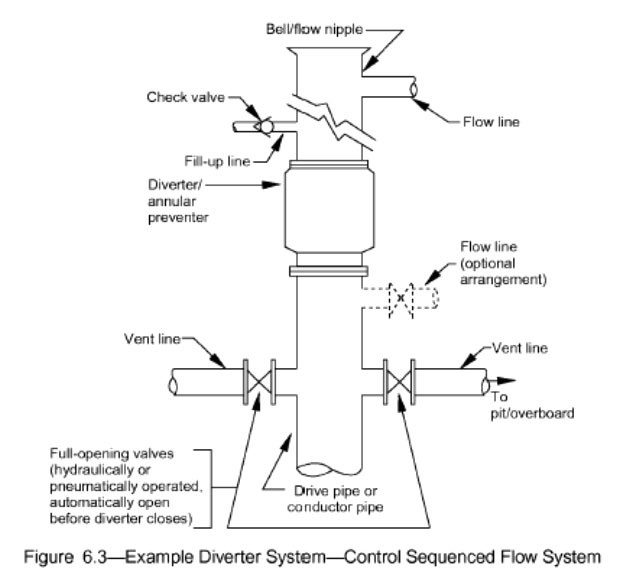
The Diverter as one of the drilling rig components, is installed on the conductor pipe before drilling of the first phase of the well and is designed to keep personnel and Rig safe. It consists of an annular type blow out preventer and is designed to divert shallow gas away from the well area while drilling a surface hole. In doing so, the well remains open, but diverting the pressure avoids fracturing a formation. Manufacturer specifications are:
- Diverter systems are manufactured according to API 16A and RP 64. The relevant ISO standard is the 13533 Spec.
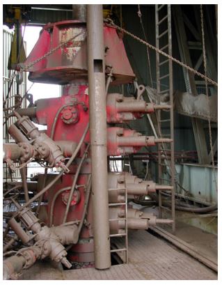
DRILLING RIG ANNULAR PREVENTER COMPONENT
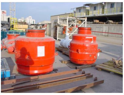
The annular preventer is part of the BOP STACK (check also BOP tests and acceptance procedure) installed on the wellhead once the anchor casing is run and cemented in the hole (Casing Cementing).
The BOP is the second and final safety device to handle the uncontrolled flow of formation fluids (hydrostatic mud pressure is the first) from well. The annular BOP is engineered to close tightly on any cylindrical body with dimensions as large as the maximum opening ID of the BOP to dimensions as small as the fully closed position.
The annular BOP can close on Drill Pipes, Drill Collars, Casing, Tubing, Tool joints the kelly, and wireline. It is not requested, as with the Ram BOP, to check the position of the Tool Joint before closing.
RAM PREVENTER
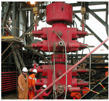
The BOP is the second barrier to stopping the uncontrolled formation of fluids from coming into the well. The BOP is only used when the first barrier (hydrostatic mud pressure) has failed. In addition to the bag preventer, a number of rams are used.
The number and type of rams in the BOP stack depends on:
- Maximum pressure that is expected in the well.
- BHA dimensions (OD).
BOPs are designed to enable the crew to change the size and type of rams easily. The types of rams in use include:
- Pipe Rams
- Variable Rams
- Blind Rams
- Blind / Shear Rams
RAM Preventers are manufactured according to API 16A. The relevant ISO standard is the 13533 Spec.
Drilling Rig BOP Control System Components
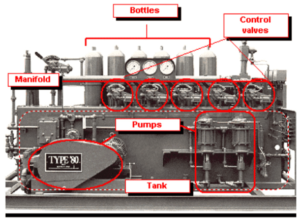
BOP Accumulators produce and store hydraulic energy to be used when BOP must be closed rapidly
because of emergency conditions. It’s equipped with the necessary controls to actuate BOP’s and
hydraulic valves during drilling and in case of a well blowout. BOP control system must provide :
- A minimum pre-determined pressurized volume to operate all BOP functions in an emergency situation.
- Reasonable accumulator recharge time.
The Accumulators are composed by:
- a tank containing hydraulic fluid (oil) at atmospheric pressure;
- one or more high-pressure pumping units to pressure fluid;
- nitrogen precharged bottle to store pressurized fluid.
The high-pressure control fluid is conveyed to a manifold and sent to closing mechanisms through
provided control valves.
- Surface BOP Control System are manufactured according to API 16D and API RP 53.
Inside BOP
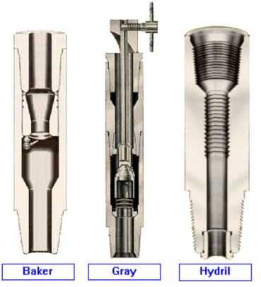
There are several components of the drilling rig in addition to the primary blowout prevention equipment
that is sometimes necessary to control a kick. The equipment which furnishes closure inside the drill string is called an “INSIDE BLOWOUT PREVENTER”.
They are installed on the top or inside the Bottom Hole Assembly with the purpose to provide a means of closing the string for well control or even to permit repair/replace some tools.
- Inside BOP is manufactured according to API 6A (and API 7 for the connections). The relevant ISO standard is the 10423 Spec.
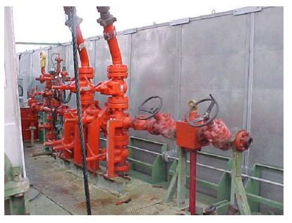
Kill & Choke Lines And Valves
The high-pressure mud circuit is the surface circuit connected to the wellhead; it is used to circulate with the well shut (driller’s method – wait and weight method) and when high-pressure ratings are recorded. Its main components are high-pressure lines and valves through which the mud flows in and out of the well during blowout control.
The high-pressure circuit has an extremely important function and therefore all parts must be regularly checked and maintained to ensure full efficiency and functionality.
The high-pressure circuit includes:
- kill lines
- choke lines
- choke manifold
- flare lines
- high-pressure valves
- adjustable chokes
Choke Manifold Component in Drilling Rig
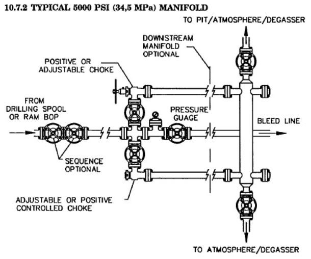
The BOP can close in the well but additional equipment is needed to allow controlled release of the well fluids, to circulate under pressure, to bleed pressure, and to allow injection against high well pressure. Variable chokes control the release of well fluids under pressure, but, because of abrasive wear and possible plugging, at least two are required. Those chokes must be manifolded in order to quickly change from one to the other.
Drilling Choke Control Panel
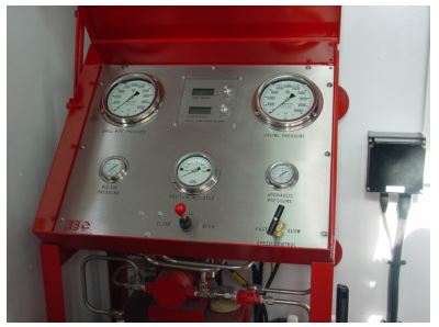
The function of the remote hydraulic choke control system is to provide reliable control of the drilling choke from one or more remote locations with the sensitivity and resolution required to perform all well control procedures which the choke valve is designed to provide, including:
- well flow shut-in procedures.
- throttling of mud, gas, liquid hydrocarbons, and formation debris at any rate of flow up to the physical capacity of the internal flow conduit.
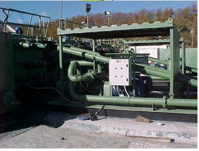
Mud Gas Separator
The mud gas separator is used to separate gas from drilling fluid that is gas cut. The separated gas can then be vented a safe distance from the rig.
- Manufacturer Specifications: Mud Gas Separator is manufactured according to API RP 53.
For an ongoing thesis / project study.