Shale Shaker performance Design is a function of:
- Vibration Pattern
- Vibration dynamics
- Deck size and configuration
- Shaker screen characteristics
- Mud rheology (plastic viscosity)
- Solids loading rate (penetration rate, hole diameter)
The impact of each is discussed in detail in the previous article (please check the link for each article). Guidelines for shaker and screen selection are also provided.
Vibration Patterns Design For Shale Shaker
Shale shakers are classified in part of the vibration pattern made by the shaker basket location over a vibration cycle (e.g. linear motion shakers). The pattern will depend on the placement and orientation of the vibrators. Four basic vibration patterns are possible,
- Circular
- Balanced elliptical motion
- Unbalanced elliptical
- Linear
Circular Motion
As the name implies, the shaker basket moves in a uniform circular motion when viewed from the side. This is a “balanced” vibration pattern design because all regions of the shaker basket move in phase with an identical pattern. In order to achieve “balanced” circular motion, a vibrator must be located on each side of the shaker basket at its center of gravity (CG) with the axis of rotation perpendicular to the side of the basket. The Brandt Tandem is a common example of a circular motion shale shaker design.
Solids Conveyance and Fluid Throughput
Circular motion shakers will not efficiently convey solids uphill. Therefore, most shale shakers of this type are designed with horizontal configurations. Fluid throughput is limited by the deck angle, but augmented slightly by the higher “G”’s normally used (see Vibration Dynamics section). The “soft” acceleration pattern does not tend to drive soft, sticky solids, such as gumbo into the screens.
Recommended Applications
- Gumbo or soft sticky solids conditions
- Scalping shakers for coarse solids removal
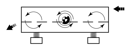
Balanced Elliptical Motion Design
The balanced elliptical motion design was introduced in 1992 and provides the fourth type of shale shaker motion design. With this type of motion, all of the ellipse axes are sloped toward the discharge end of the shaker screen. Balanced elliptical motion can be produced by a pair of eccentrically weighted, counter-rotating parallel vibrators of different masses. This motion can also be produced by a pair of eccentrically weighted, counter-rotating vibrators that are angled away from each other (Figure 1).
The ellipse aspect ratio (major axis to minor axis) is controlled by the angle between vibrators or by different masses of the parallel vibrators. The greater the minor axis angle, or angle of vibrators relative to each other, the broader the ellipse and the slower the solids conveyance. A thin ellipse with a ratio of 3.5 will convey solids faster than a fat ellipse with a ratio of 1.7. The typical operating range is 1.5 to 3.0, with the lower numbers generating slower conveyance and longer screen life.
Balanced elliptical motion shale shakers design can effectively remove gumbo if they are sloped downward toward the discharge end, just like linear motion. The increased physical size of these units (and an accompanying increase in deck screen surface area) allows the use of even finer screens than those used on circular or elliptical motion shale shaker designs. In conventional unbalanced elliptical and circular motion designs, only a portion of the energy transports the cuttings in the proper direction, toward the discharge end. The balanced elliptical motion continues transporting the cuttings toward the discharge end of the screen in the same manner as linear motion.
The latest design has the motors placed above the basket and produces a ‘lazy’ elliptical motion
Recommended Applications
- General solids removal. Equally good in water-based and oil-based drilling fluids
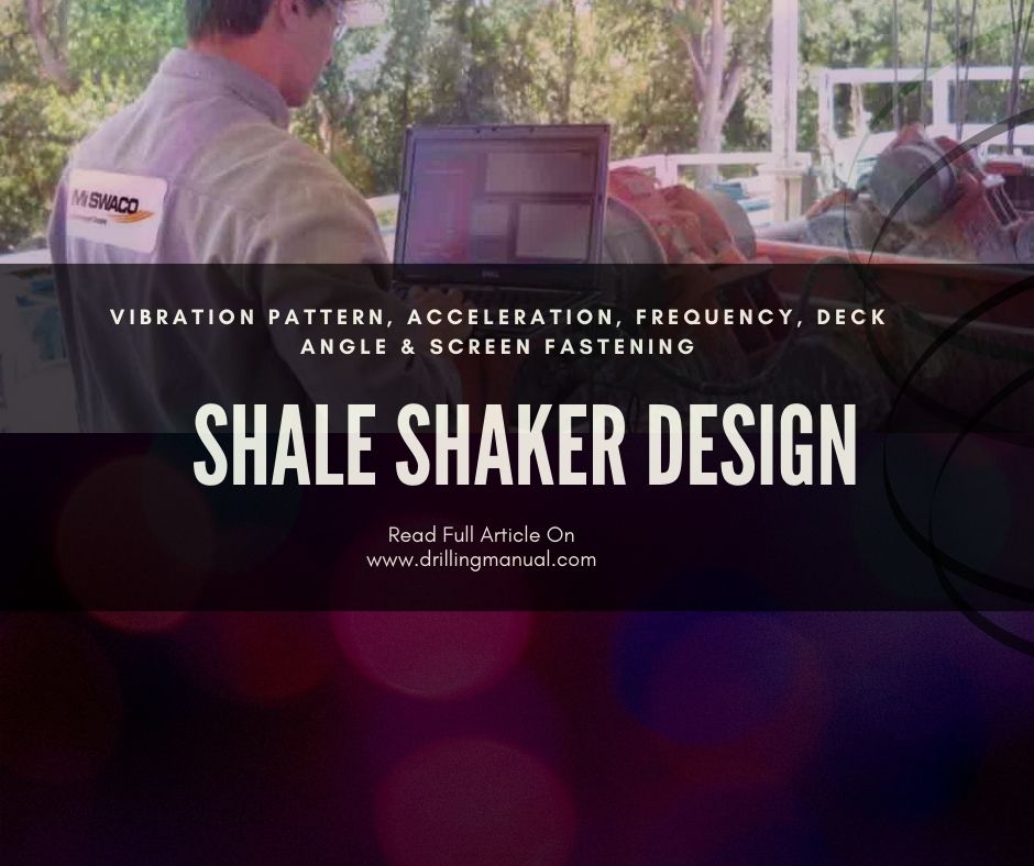
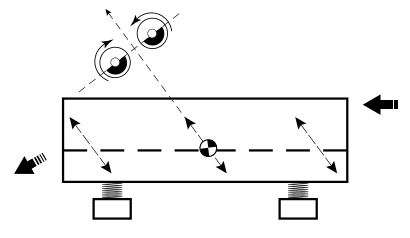
Unbalanced Elliptical Motion Design
The difference between circular motion and unbalanced elliptical notion is a matter of vibrator placement. To achieve unbalanced elliptical motion, the vibrators are typically located above the shaker basket. Because the vibrator counterweights no longer rotate about the shaker’s center of gravity, torque is applied to the shaker basket. This causes a rocking motion that generates different vibration patterns to occur along the length of the basket, hence the item “unbalanced”.
This figure illustrates how the vibration pattern may change along the length of the basket. At the feed end of the shaker, an elliptical vibration pattern is created; the angle of vibration is pointed toward the discharge end. In this region, forward solids conveyance is good. However, at the discharge end of the shaker, the angle of the elliptical pattern is pointed back towards the feed end. This will cause the solids to convey backward unless the deck is pitched downhill at a sufficient angle to overcome the uphill acceleration imparted on the solids by the shaker motion.
Solids Conveyance and Fluid Throughput
The downhill deck orientation restricts the unbalanced elliptical motion shaker’s ability to process fluid, mud losses can be a concern. However, the deck orientation is beneficial for removing sticky solids such as gumbo.
Recommended Applications
- Gumbo, or soft sticky solids conditions
- Scalping shakers for coarse solids removal
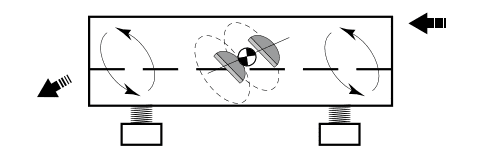
Linear Shale Shakers Design
Linear motion is achieved by using two counter-rotating vibrators which, because of their positioning and vibration dynamics, will naturally be operated in phase. They are located so that a line drawn from the shaker’s center of gravity bisects at 90˚ a line drawn between the two axes of rotation.
Because the counterweights rotate in opposite directions, the net force on the shaker basket is zero except along a line passing through the shaker’s center of gravity. The resultant shaker motion is, therefore “linear”. The angle of this line of motion is usually at 45-50˚ relative to the shaker deck to achieve maximum solids conveyance. Because acceleration is applied through the shaker CG, the basket is dynamically balanced; the same pattern of motion will exist at all points along with the shaker.
Solids Conveyance and Liquid Throughput
Linear motion shakers have become the shaker of choice for most applications because of their superior solids conveyance and fluid handling capacity. Solids can be strongly conveyed uphill by linear motion. The uphill deck configuration allows a pool of liquid to form at the shaker’s feed end to provide additional head and high fluid throughput capability. This allows the use of fine screens to improve separation performance. The Derrick Flo-Line Cleaner is one example of a linear motion shale shaker design.
One drawback to linear motion shakers is their relatively poor performance in processing gumbo. The short vibration stroke length when combined with long basket lengths, uphill deck angles, and strong acceleration forces tends to make the soft gumbo “patties” adhere to the screen cloth. The removal of gumbo is important prior to feeding to a linear motion shaker.
Recommended Applications
All applications where fine screening is required.
Acceleration In Shale Shaker Performance Design
During the vibration cycle, the shaker basket undergoes acceleration which changes in both magnitude and direction. As discussed previously, the placement of the vibrators determines the vibration pattern and therefore the net acceleration direction during the vibration cycle. The mass of the counterweights and the frequency of the vibration determine the magnitude of the acceleration.
The vertical component of acceleration has the most effect on shaker liquid throughput. We relate the vertical components of acceleration and stroke length to frequency by the following equation:
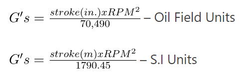
Where:
- The stroke length is the total vertical distance traveled by the shaker basket.
- The G-force is measured from midpoint to peak.
Acceleration of one “G” is the standard acceleration due to gravity (386 in./sec2 or 9.81/sec2). Most shakers operate at accelerations within the range of 2.5 – 7.0 G’s, depending upon the vibration pattern. Field experience has shown this range offers the best compromise between throughput capacity and screen life.
Many manufacturers report the acceleration of linear motion shakers along the line of motion. This yields a larger number and looks good on the specification sheet. However, unless the angle of vibration is also specified, it reveals little about the performance of the shaker.
Some shakers have adjustable counterweights to vary acceleration. Although flow capacity and cuttings dryness improve with increased acceleration, screen life is negatively affected. By reducing the “G”s when extra flow capacity is available, screen life may be improved.
Frequency (rpm), stroke length
The vibrator frequency of most shale shaker designs is not normally adjustable. The vibrators typically rotate at a nominal RPM or 1200 or 1800 at 60Hz. Stroke length varies inversely with rpm. A higher rpm will result in a shorter stroke length at the same acceleration.
The effect of vibrator frequency and stroke length on shaker processing rate has been evaluated in the laboratory. The results of these tests show improved shaker flow capacity in the presence of solids with decreased rpm (or conversely, increased stroke length) at the same G level. Therefore, the term “high speed” should not be used to mean “high performance” since the opposite relationship is often more correct.
The main disadvantage to lower frequency shale shaker design is that the mud tends to “bounce” much higher off the screens and cover the area around the shakers with a fine coating of mud. More frequent housekeeping is required to maintain a safe environment around the shakers. Longer stroke lengths also tend to reduce screen life.
deck angle
Because linear motion shakers will convey uphill, most provide an easily adjustable deck angle feature to optimize fluid throughput capacity and cuttings conveyance velocity. Uphill deck angles also provide protection against overflow due to surges at the flowline.
At deck angles greater than 3o, solids grinding in the pool region can be a problem. Although fluid throughput increases with uphill deck angle, cuttings conveyance decreases. Solids conveyance within the pool region is slower than out of the pool due to viscous drag forces and the differential pressure created across the cuttings load by the hydrostatic head of the fluid. If the deck angle is too high, a stationary mound of solids can build up in the pool even though conveyance is observed at the discharge end. The vibrating action of the screen and extended residence time will tend to grind soft or friable cuttings before they have the opportunity to be conveyed out of the pool. This condition should be avoided since the generation of fines in the mud is definitely not desired.
To check for this problem, observe the feed end of the shaker at a connection immediately after circulation is stopped. There should not be a disproportionate amount of solids accumulated at the feed end. The problem can be rectified by lowering the deck angle until the solids mound is eliminated.
screen fastening and support Design For Shale Shaker
The type of screen panel dictates the type and amount of support and fastening system necessary. The screen fastening and support structure provide the following functions:
- Prevent leakage past the screens
- Expedite screen replacement
- Provide even tension on screens to extend screen life
The two types of screen panels are commonly labeled as “pretensioned” and “non-pretensioned” panels. However, these terms do not exactly describe the construction since many nonpretensioned panels are, indeed, pre-tensioned. The terms “rigid frame” and “hook strip” more correctly differentiate the two main panel types.
hook strip screen panels
This is the most common type of panel, consisting of one to three layers of screen cloth. The cloth is frequently bonded to a thin perforated metal grid plate or a plastic grid. The next figure shows the construction of a typical hook strip screen. The screen panel is tensioned on the shaker deck by an interlocked hook strip and drawbar arrangement located on both sides of the shaker. Three or more tensioning bolts are used to pull each drawbar down and towards the side of the basket. This seats the screen on the shaker deck and distributes even tension along the hookstrip.
Fine Middle Layer
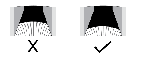
These panels are not rigid; the shaker deck must be crowned to maintain screen
1. The screen cloth is tensioned and glued directly to the steel frame. Additional glue lines may be included between the frame members to provide additional support. The bonding pattern divides the panel into 3 – 4 in (76 – 102 mm) wide strips orientated parallel to the flow. This design is used in the fluid systems Model 500.
2. This panel design maximizes the usable screening area. However, the large unsupported area normally limits cloth selection to the heavier grades with lower flow capacity. The panel is not normally considered repairable.
3. Alternatively, the screen cloth may be bonded to a perforated metal backing plate similar to a hook strip screen. The metal backing plate is then bonded to the support to create a rigid panel. The Brandt ATL-1000 and the Thule VSM-100 use this type of panel.
The usable screen area is reduced by the performed plated design, but this is offset by the option of using higher conductance screen cloth, reparability, and better screen life under high solids loading conditions.
three-dimensional screens
In recent years three-dimensional screens have been introduced to the oil industry. This wave design increases the area of the screen by 40% over the flat screens. This increase in conductance is only relevant if the screen is completely submerged in drilling fluid.