There are a lot of Water Based Drilling Fluid systems that are used in drilling oil and gas wells. In this article we will talk about the following fluid systems:

- Spud Mud
- Guar Gum
- Lime Flocculated Bentonite Fluid System
- KCL-PHPA-Polymer Fluid System
- KCL-PHPA-Polymer-Glycol Fluid System
- Saturated Salt Fluid Systems
- Sodium Silicate Fluid System
- Mixed Metal Hydroxide Fluid System
- Ultra Low Invasion Fluid
- Perm Drill Drill-In Fluid SystemFormate Fluid System
Spud Mud
Spud mud is a simple Bentonite (Gel) mud system that is used when spudding a well to drill the top-hole section. Surface formations are usually unconsolidated, so hole washout and sloughing are common, and fluid inhibition has limited benefit. The priority is to drill the top-hole section as fast as possible, and then run and cement the casing string before the hole starts to collapse. Spud mud is made by mixing Bentonite in freshwater, using Soda Ash to reduce the water hardness, and Caustic Soda to obtain alkalinity around 9.5 pH.
Drilling top-hole sections is usually a busy period for building reserve mud due to fast ROPs, but Bentonite takes a few hours to hydrate (yield) fully. To ensure sufficient spud mud is available when drilling the top hole, a concentrated Bentonite slurry is usually prepared in the mud tanks at 40 ppb. This volume is then split between two mud tanks before cutting the gel concentration back to 20 ppb with fresh water. The Caustic Soda is then added to the 20 ppb gel before pumping down-hole.
The standard formulation for mixing spud mud is as follows:
| Product | Function | Concentration |
| Fresh Water | Base Fluid | – |
| Soda Ash | Water Hardness Reducer | 0.5 ppb* |
| Bentonite (Gel) | Viscosifier | 40 ppb |
| Caustic Soda | Alkalinity | 0.5 ppb* |
*Note The exact amount of Soda Ash and Caustic Soda required should be adjusted after testing the total hardness of the drill water.
Mixing Procedure:
- Fill the tank with the required amount of freshwater.
- Add 0.5 ppb Soda Ash to reduce the water hardness for optimum gel hydration.
- Add 40 ppb Bentonite and leave to hydrate (around six hours).
- Cut the 40 ppb Bentonite concentration to 20 ppb with fresh water.
- Add 0.5 ppb Caustic Soda (use a chemical barrel) before pumping down-hole.
Offshore rig exploration wells may not have a Marine drilling Riser when spudding wells, so returns are discharged at the seabed. The top-hole section is therefore drilled with seawater while pumping Bentonite sweeps at regular intervals for hole cleaning. These sweeps are designed to provide high low-end rheology for cleaning large diameter holes that are drilled with seawater. They should be pumped at frequent pre-determined intervals.
The onshore and offshore hole is usually filled with viscous 20 ppb Bentonite slurry, which may be weighted or inhibited for improved wellbore stability, any time that the hole is left static for an extended period, or at section TD before pulling out to run casing. This displacement slurry is designed to keep cuttings in suspension and improve borehole stability by providing fluid loss control and hydrostatic pressure.
Ideally, the 20 ppb displacement slurry is prepared by cutting 40 ppb pre-hydrated Bentonite with freshwater because this produces a better filter cake and the viscosity is more stable, making it better for maintaining large diameter hole stability. This dilution is made with drill water on land rigs (Check also types of drilling rigs), but seawater is usually used on offshore wells for speed of preparation and to conserve drill water stocks.
In the case of the offshore well, a Temporary Guide Base for the BOP is run with the casing. Once the casing is cemented, the BOP is run with the Marine Riser and is installed on the Temporary Guide Base, enabling returns to be recovered on the rig to form a closed circulating system
Guar Gum – Water Based Drilling Fluid Systems
Guar Gum is often used as an alternative to Bentonite for high-viscosity sweeps when drilling top-hole offshore because it is quick and easy to mix in seawater. Guar Gum is useful for keeping up with drilling progress and for conserving stocks of fresh water and/or Bentonite. The standard formulation for mixing Guar Gum is as follows:
| Product | Function | Concentration |
| Sea Water | Base Fluid | – |
| Guar Gum | Viscosity | 3-4 ppb |
Mixing Procedure:
- Fill the tank with the required amount of seawater.
- Add 3 ppb to 4 ppb Guar Gum and use when ready.
Guar Gum is not tolerant to high pH or elevated Calcium ion concentrations, so tanks must be clean before mixing. Care is required to add Guar Gum slowly at the mixing hopper in order to prevent “fish- eyes”, which will reduce the effectiveness of the product. Guar Gum will degrade within 24 hours under most conditions, and viscosity will eventually revert back to that of the base fluid (brine or water). The use of a biocide will preserve Guar Gum viscosity for a longer period of time.
Guar Gum sweeps are designed to provide high low-end rheology for cleaning large diameter holes that are drilled with seawater. However, viscous Guar Gum is not as effective as viscous Bentonite for hole cleaning, so the volume and frequency of the sweeps should be increased when using Guar Gum. Viscous Guar Gum is not suitable as a viscous slurry for filling the hole before pulling out to run casing because it does not develop effective gel strengths, the viscosity is not long-lasting and there is no fluid loss control.
Lime Flocculated Bentonite Fluid Systems
Pre-hydrated Bentonite flocculated with seawater and Lime is the preferred sweep for drilling top-hole sections. These sweeps are designed to provide high low-end rheology to clean large diameter holes that are drilled with seawater. They should be pumped at frequent pre-determined intervals.
Lime Flocculated Gel Mud is made by mixing 40 ppb Bentonite spud mud with fresh water, and then diluting 2 parts by volume of mud with 1 part by volume of seawater before flocculating with 1 ppb Lime. The standard formulation for Lime Flocculated Gel Mud is as follows:
| Product | Function | Concentration |
| Fresh Water | Base Fluid | – |
| Soda Ash | Water Hardness Reducer | 0.25 ppb* |
| Bentonite (Gel) | Viscosifier | 40 ppb |
| Lime | Flocculation/Alkalinity | 1.0 ppb |
*Note The exact amount of Soda Ash required should be adjusted after testing the total hardness of the drill water.
Mixing Procedure:
- Fill the tank with the required amount of freshwater.
- Add 0.25 ppb Soda Ash to reduce the water hardness for optimum gel hydration.
- Add 40 ppb Bentonite and leave to hydrate (around six hours).
- Transfer required volume to a separate tank and cut back to 30 ppb Gel with seawater.
- Add 1 ppb Lime to flocculate the Bentonite slurry.
Gel flocculation with seawater and Lime should be performed in a separate tank than that used for preparing the 40 ppb Bentonite pre-mix. However, this may not be possible due to limited tank space or other factors.
The hole is usually filled with viscous 20 ppb Bentonite slurry, which may be weighted or inhibited for improved wellbore stability, any time that the hole is left static for an extended period, or at section TD before pulling out to run casing, using the base formulation for Spud Mud earlier in this section. This displacement slurry is designed to keep cuttings in suspension and improve borehole stability by providing fluid loss control and hydrostatic pressure.
KCL-PHPA Polymer Water Based Drilling Fluid Systems
The most extensive and difficult formations to drill are those containing shales that have been compressed and partially dehydrated over time. The process of drilling a hole partially relieves the confining stresses on the shale, which may be sufficient to cause mechanical failure of the rock. The mechanism of failure is the initial formation of a crack (crack initiation) followed by many small fissures (crack propagation).
If drilling fluid inhibition is poor then the shale will absorb water from the drilling fluid, swell up and destabilize the surrounding shale. The reaction to water will depend on the exact mineralogy of the clays present, ranging from plastic deformation of the shale to give tight hole conditions, or brittle failure leading to caving and sloughing hole conditions, both of which can be controlled by mud density.
The water-based KCL-PHPA Polymer drilling fluid system addresses the inhibition problem to produce stable drilled cuttings which, combined with a fluids system with lower solids content due to the density provided by the Potassium Chloride brine, combine to give excellent hole cleaning, low erosion rates, and fast penetration rates.
Shale Inhibition Mechanisms
The water-based KCL-PHPA Polymer system provides effective inhibition when drilling reactive shales through two mechanisms:
- Potassium Chloride provides a source of Potassium ions, which exchange with sodium or calcium ions already present in certain clay minerals. The Potassium ion is very small, which gives it a relatively high charge density compared to other larger ions. The Potassium ions are small enough to fit between the clay platelets without distorting the shale lattice. After adsorbing onto the exchangeable cation sites in the shale lattice, the higher charge density of the Potassium ions holds the platelets together to produce a stable, non-expanding form. This helps to minimize clay and shale hydration, swelling, and dispersion.
- PHPA (Partially-Hydrolysed Poly-Acrylamide) is a very high molecular weight polymer that adsorbs onto clay and shale surfaces, coating the wellbore and encapsulating drilled cuttings with a viscous polymer layer. This acts as a barrier to prevent water invasion into clays and shales, which once again helps to minimize clay and shale hydration, swelling, and dispersion. The PHPA coating helps to keep drilled cuttings intact as they travel up the annulus, improving solids control efficiency on the surface and helping to control the build-up of solids in the drilling fluid.
Mixing & Treatments
The KCL-PHPA Polymer system is easy to mix and the inhibitive properties are easy to adjust according to clay and shale reactivity while drilling. The cationic exchange is brought about by introducing the potassium ion into the mud as a Potassium Chloride brine solution ranging from 3% to 15% (10 to 50 ppb). However, the Potassium ion concentration needs to be adjusted carefully to suit shale reactivity, because low concentrations will encourage shale hydration and dispersion, while over-treatment may dehydrate and destabilize the wellbore.
Regular treatments are usually required to maintain Potassium ion and PHPA concentrations that are depleted through drilled cuttings removal at surface. The drilling fluid system is versatile and can be converted into more inhibitive water-based drilling fluid systems using appropriate additives. With increasing focus on environmental protection, the discharge of chloride-based fluids is restricted in some environmentally sensitive areas of the world, but Potassium ions can be provided using environmentally acceptable fluids like Potassium Formate.
A typical formulation for a KCL-PHPA-Polymer drilling fluid system is as follows
| Product | Function | Concentration |
| Water (Fresh or Sea Water) | Base Fluid | 1 bbl |
| Caustic Soda | Alkalinity | 0.5 ppb |
| KCL | Potassium Inhibition | Up to 35 ppb |
| Xanthan Gum | Viscosifier | 1 ppb |
| PAC | Fluid Loss Control | 4 ppb |
| PHPA | Encapsulating Polymer | 1 ppb |
| Barite | Density | As Required |
Mixing Procedure:
- Fill tank with required amount of fresh water or seawater.
- Adjust pH to around 9.5 to 10.0 with Caustic Soda (use a chemical barrel).
- Add the required amount of Potassium Chloride powder.
- Add 1 ppb Xanthan Gum slowly at 5 minutes per sack.
- Add 4 ppb PAC.
- Add 1 ppb PHPA slowly at 10 minutes per sack.
- AddBaritetoobtaintherequireddrillingfluiddensity.
The KCL-PHPA-Polymer system should not be formulated with Bentonite for viscosity because the fluid is designed to control clay and shale hydration. Dispersants and thinners should not be used for similar reasons because one of the objectives of the system is to prevent shale dispersion so that drilled solids can be removed by the Solids Control Equipment.
Fluid System Guidelines
The KCL-PHPA-Polymer fluid system has proven very adaptable to a wide range of conditions world side and can be formulated in freshwater, seawater, and saturated saltwater. It is also tolerant to cement and anhydrite contamination. The components that control the hydration and dispersion of water-sensitive shales, namely the Potassium Chloride and the PHPA polymer, do not directly contribute any other property to the drilling fluid, so additional components are required to control flow properties and provide fluid loss control.
Rheology
Rheological mud properties are controlled through the use of Xanthan gum polymers such as Biopoly-E. The flow properties are unaffected by salinity when using this type of polymer, with good resistance to shear and temperature degradation. The rheology is more shear-thinning than clay-based systems at low densities, with excellent hole cleaning performance. The polymer develops progressive gel strengths, which allow suspension of weighting agents without the need for high viscosities.
Fluid Loss Control
The main fluid loss control additive is PAC, which is effective over a range of salinities. Regular PAC (PAC-R) provides fluid loss control and additional viscosity, for use when rheology also needs to be increased. PAC Super-Lo (PAC-SL) gives fluid loss control without additional viscosity, for use when drilling fluid rheology is already adequate. Polytrex is a non-viscosifying fermentation-resistant starch that can also be used for improving fluid loss control without increasing fluid viscosity.
Shale Inhibition
The main method of inhibition is the Potassium Ion concentration. Laboratory analysis of shale samples from offset wells will give an indication of shale reactivity and the level of inhibition required. However, the actual level of inhibition should be determined by inspecting the drilled cuttings at the shale shakers. They should be firm and dry on the inside when broken in half, which indicates low fluid invasion. If the cuttings are soft and the MBT (Methylene Blue Test) reveals high clay content, then the level of inhibition needs to be raised by increasing the KCL and PHPA concentrations.
The Potassium ion concentration is measured by precipitating out Potassium Perchlorate in a known volume of filtrate. The filtrate is then centrifuged to determine the volume of the precipitate present, which can be converted into the Potassium Ion concentration using a calibration chart. It is important to maintain shale inhibition at the required level because if the KCL concentration is too low then dispersion will occur, which will lead to a build-up in solids. Shale dehydration may occur if the KCL concentration is too high, which may lead to brittle failure in the form of caving and sloughing.
Continuous treatments with Potassium Chloride are required because the Potassium ion concentration will deplete due to adsorption onto the cationic exchange sites on the wellbore and cuttings while drilling. The rate of depletion will depend on shale reactivity and ROPs. Regular monitoring of the Potassium Ion concentration is required to so that correct maintenance treatments are made without under-treating or over-treating.
PHPA Concentration
Shale Drill is a PHPA with extremely high molecular weight (in the 6 to 10 million range) that adsorbs strongly onto clay surfaces to form a viscous layer that minimizes water invasion into micro-fissures, preventing further deterioration of the shale structure. This polymer is effective at low concentrations, so high concentrations should be avoided because this will affect rheology and restrict fluids handling at the shale shakers, which may restrict circulation rates.
As with Potassium Chloride, PHPA will deplete due to adsorption onto the wellbore and onto drilled cuttings that are removed at the shale-shakers while drilling. The rate of depletion depends on the ROP and on the nature of the drilled cuttings. Higher ROPs generally produce larger drilled cuttings, and lower ROPs generally produce smaller drilled cuttings. The depletion rate of PHPA for a fixed volume of smaller drilled cuttings will be higher than that for the same volume of larger drilled cuttings because the smaller cuttings have a larger overall surface area for PHPA adsorption.
Shale Drill is available in powder and liquid form. The powder form, Shale Drill (P), is generally used when mixing fresh mud since there is usually sufficient time for the polymer to yield fully. Shale Drill (L) is the “ready-mixed” form of Shale Drill (P) with 35% activity, which is added slowly to the active tank while drilling, with the agitators running. Overtreatment should be avoided because this will increase the overall fluid rheology, which will make it difficult to screen out solids at the shakers.
Solids Content
The KCL system is a non-dispersed flocculated fluid, so toleration for high levels of active drilled solids is not as good as a dispersed clay system. It is therefore important to concentrate on the primary solids removal equipment by selecting the finest screens for the shale-shakers, where possible. Removal of solids in this type of fluid is facilitated by maintaining low viscosities and low gels, and by avoiding over-treatment with PHPA. Whole mud dilution is effective for controlling the build-up of solids because ultrafine solids are removed from the circulating system while maintaining the Potassium Ion concentration.
Other Properties
Other properties are easy to control and maintenance usually requires minor treatments. The pH is normally maintained around 9.0 since high pH values tend to disperse clays and may have a detrimental effect on polymer performance. High pH will also encourage PHPA hydrolysis, with the release of ammonia gas that is very noticeable. The system has good tolerance to salt contamination, while cement contamination should be treated with Sodium Bicarbonate. The system has proved to be stable in the field to temperatures in excess of 300°F (150°C).
KCL-PHPA Polymer-Glycol – Water Based Drilling Fluid Systems
Although suitable for a range of water-based drilling fluid systems, Glycol is usually added to the KCL-PHPA Polymer system to provide enhanced inhibition when drilling highly reactive shales. Glycol is a completely water-soluble synthetic polymer that adsorbs strongly at the surface of troublesome shales to form a water-repellent barrier. This reduces swelling and inhibits shale dispersion, resulting in a high-performance drilling fluid that is an environmentally acceptable alternative to oil-based drilling fluid systems.
TAME glycols (Thermally Activated Micro-Emulsions) exhibit “inverse solubility”, in that they are water-soluble at ambient temperatures, but become less soluble at elevated temperatures. The insoluble glycol forms a micro-emulsion at elevated wellbore temperatures, which produces enhanced fluid loss control and inhibition. Other benefits are improved wellbore stability, improved cuttings integrity, reduced bit balling and fewer stuck pipe incidents, along with the fact that glycols are non-damaging to reservoir formations.
If the conventional KCL-PHPA Polymer system is unable to provide the required inhibition, then glycol can be added to convert the fluid into a highly inhibitive system. Drilled cuttings will be firmer and more resistant to dispersion while traveling up the annulus, which will reduce the build-up of solids in the drilling fluid. This will help to improve solids control efficiency and lower dilution rates. Enhanced inhibition is achieved through two mechanisms:
1. Clay Adsorption – The glycol competes with water for the same cation sites on the clay surfaces, which reduces water activity and the potential for shale hydration.
2. Cloud Point Behavior – The cloud point of a TAME glycol is the temperature where the glycol starts to form micro-bubbles and separate out from the water, blocking the formation pores to prevent filtrate invasion
Fluid System Formulation
A typical formulation for a KCL-PHPA-Glycol drilling fluid system is as follows:
| Product | Function | Concentration |
| Water (Fresh or Sea Water) | Base Fluid | 1 bbl |
| Caustic Soda | Alkalinity | 0.5 ppb |
| KCL | Potassium Inhibition | Up to 35 ppb |
| Xanthan Gum | Viscosifier | 1 ppb |
| PAC | Fluid Loss Control | 4 ppb |
| PHPA | Encapsulating Polymer | 1 ppb |
| Glycol | Shale Inhibition | As Required (%) |
| Barite | Density | As Required |
Mixing Procedure:
- Fill the tank with the required amount of freshwater or seawater.
- Adjust pH to around 9.5 to 10.0 with Caustic Soda (use a chemical barrel).
- Add the required amount of Potassium Chloride powder.
- Add 1 ppb Xanthan Gum slowly at 5 minutes per sack.
- Add 4 ppb PAC.
- Add 1 ppb PHPA slowly at 10 minutes per sack.
- Add the required amount of Glycol
- Add Barite to obtain the required drilling fluid density.
Fluid System Guidelines
Fluid maintenance is the same as for the KCL- PHPA-Polymer system, the only difference being the presence of Glycol (DCP-208), where cloud point is monitored.
Cloud Point Temperature (CPT)
The Cloud Point Temperature is the temperature at which a TAME glycol starts to separate or “cloud out”, so-called due to the cloudy appearance. Glycols never cloud out completely at the CPT, but the volume of clouded-out glycol will increase as the temperature continues to increases. The CPT is affected by the type of glycol, glycol concentration, and salt concentration. An increase in glycol concentration will decrease the CPT, and an increase in salt concentration will also decrease the CPT, as shown in the chart overleaf.
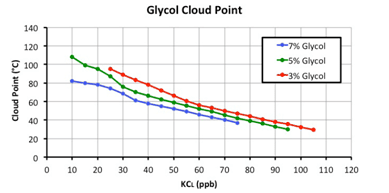
As can be seen from the chart above, the CPT of glycol can be adjusted to suit formation temperatures by changing the concentration of the glycol and/ or concentration of the KCL brine. The CPT can be increased by reducing the glycol concentration and/or reducing the KCL concentration as drilling progresses since formation temperatures increase with depth.
CPT Determination
The CPT of a TAME glycol can be measured as follows:
- Collect a sample of filtrate from a filter press in a measuring cylinder.
- Place a thermometer in the measuring cylinder and place the measuring cylinder in a flask of water.
- Place the flask of water on a hot plate and heat slowly.
- Record the temperature when the filtrate starts to turn cloudy.
- Remove the flask of water from the hot plate and check that the cloudy filtrate turns clear as it cools down (If the filtrate does not go clear again then the cloudy appearance may be caused by some form of precipitation, such as CaCO ). If this is the case, heat the filtrate again until it becomes really cloudy.
- If CPT measurements exceed 90°C, add some salt to the water in the flask in order to increase the boiling point.
Glycol Concentration Determination
A close approximation of the Glycol (DCP-208) concentration in a mud system can be obtained by making use of its inverse solubility in water, as follows:
- Take a sample of active mud that has been allowed to cool to ambient temperature and homogenize for one minute using a Hamilton Beach Mixer at medium speed.
- Run an HTHP fluid loss test at ambient temperature to collect filtrate for analysis.
- Saturate the filtrate with Sodium Chloride powder in order to decrease the CPT so that all the glycol will cloud out in the next step (Only a small percentage of the glycol clouds out at the CPT, so the temperature needs to be considerably higher to cloud out all the glycol).
- Using at least 10 mls of filtrate (use more if possible as this will increase accuracy), place the measuring cylinder in hot water at around 80°C.
- As the filtrate warms up, phase separation will occur and the quantity of glycol (DCP-208) can be read from the top from the measuring cylinder. Adding a few drops of light oil after separation has occurred will create a smoother interface at the glycol phase and improve accuracy. The quantity measured can then be expressed as a volumetric percentage of the initial filtrate volume, because the initial filtrate volume will have increased after adding the Sodium Chloride salt. See figure 1 below.
Glycol % (v/v) = [Glycol volume (mls) ÷ Initial Filtrate Volume (mls)] x 100
Glycol Concentration should be reported to the nearest 0.5%.
Saturated Salt Water Based Drilling Fluid Systems
Saturated salt Water-Based Drilling Fluid systems are used when drilling through salt formations (evaporates), which usually take the form of salt domes or massive beds. Salt formations can range from sodium, potassium, or magnesium chloride to complex mixed blends, and often contain other evaporate minerals such as anhydrite, gypsum, limestone, or dolomite inter-bedded in the salt structure. Saturated Salt systems are designed to maintain wellbore stability while drilling salt formations, which are plastic and deformable at high temperatures and pressures.
The priority while drilling salt formations is to avoid mechanically stuck pipe due to salt creep, and to control the amount of washout. Large washouts will affect hole cleaning efficiency and will also contaminate the saturated salt fluid system with formation salts, which may contain divalent ions like magnesium that could affect fluid rheology through cross-linking of polymers. These problems can be reduced by maintaining the drilling fluid close to saturation in order to minimize the amount of salt formation that dissolves.
The water based drilling fluid system should be fully saturated before penetrating the salt formation, in order to avoid large washouts at the top of the salt. Saturation is achieved by adding salt (Sodium Chloride) to the mud system until the saturation point is reached around 315,000 mg/l, with chloride content around 190,000 mg/l. Chloride salinity should then be reduced and maintained around 155,000 to 165,000 mg/l while drilling the salt formation. This will allow sufficient washout to avoid mechanically stuck pipe due to salt creep.
The salinity of the drilling fluid needs to be checked at regular intervals while drilling salt sections, making dilutions with treated water to reduce salinity when necessary. If salinity is too low then the salt formation will be dissolved by the drilling fluid, which may produce large washouts. If salinity is close to saturation then a gauge hole will be drilled but the BHA may become mechanically stuck due to salt creep. Treated water pills can also be circulated if a tight hole is encountered or to free stuck pipe due to salt creep.
Fluid System Formulation
A typical formulation for a KCL-PHPA-Polymer water based drilling fluid system is as follows:
| Product | Function | Concentration |
| Water (Fresh or Sea Water) | Base Fluid | – |
| Soda Ash | Calcium Treatment | 1.5 ppb |
| Bentonite | Viscosifier | 5 ppb |
| Caustic Soda | Alkalinity | 1.5 ppb |
| Flowzan | Viscosifier | 1 ppb |
| Antisol 100 | Fluid Loss Control | 3 ppb |
| Antisol 30,000 | Fluid Loss Control | 2 ppb |
| KCL | Shale Control | As Required |
| NaCL | Salinity | 108 ppb |
| FC-10 | Thinner/Dispersant | As Required |
| Drilling Detergent | Surface Active Agent | As Required |
| Lube | Lubricant | As Required |
| No Foam | Defoamer | As Required |
| Barite | Density | As Required |
Mixing Procedure:
The Saturated Salt water based drilling fluid system can be formulated with freshwater or seawater. The Potassium Chloride provides inhibition to reduce the hydration and dispersion of shales, which could be present above, below, or as inter-bedded stringers within the salt formation.
- Fill the tank with the required amount of freshwater or seawater.
- Add the required amount of Soda Ash to treat out calcium hardness.
- Add the required amount of Bentonite to improve the quality of the filter cake.
- Adjust pH to around 9.5 to 10.0 with Caustic Soda (use a chemical barrel).
- Add 1 ppb Flowzan slowly at 5 minutes per sack.
- Add Antisol 100 slowly at 2 minutes per sack.
- Add Antisol 30,000 slowly at 5 minutes per sack.
- Add the required amount of Potassium Chloride powder for shale inhibition.
- Add the required amount of Sodium Chloride powder.
- Add Barite to obtain the required drilling fluid density.
Additions of FC-10, Drilling Detergent, Lube, and No Foam should only be added to the saturated salt fluid system as and when they are required while drilling.
The saturated salt fluid system is relatively simple to run, as long as salinity is monitored closely. Foaming may occur with high concentration brine systems, so defoamers (e.g. No Foam) should be available to deal with this issue.
Fluid System Guidelines
Density
The density is provided by the density of the saturated brine, using barite when higher densities are required. The solids control equipment should be optimized to control any increase in density due to a build-up of drilled solids. When density needs to be increased, mud salinity should be checked in case it is on the low side. If this is the case then sodium chloride salt should be added first to restore mud salinity. Barite can then be added to achieve the required mud density. The density should be adjusted according to hole conditions while drilling and should be increased at the first indications of packing-off, pore pressure increase, wellbore instability, or saltwater flow.
Rheology
Rheological properties are controlled through the use of Xanthan gum polymers such as Flowzan. Plastic Viscosity (PV) should be kept as low as possible through optimum use of all the available solids control equipment to prevent a build-up of LGS, which could have an adverse effect on rheological properties. ROPs should be controlled at all times because high ROPs will load the annulus with cuttings and produce an increase in LGS, resulting in an increase in density and viscosity which could induce formation losses in formations above or below the salt formation. Dilutions or treatments with a thinner (e.g. FC-10) should be made when rheology needs to be reduced.
PH and Alkalinity
Caustic Soda is used for pH and alkalinity control to improve the performance of the mud products and provide corrosion control. The pH should be maintained around 9.5 to 10.0 using pre-dissolved Caustic Soda in a chemical barrel, making sure that the Caustic Soda powder or pellets are added to water in the chemical barrel.
Fluid Loss Control
The main fluid loss control additive is Antisol, a PAC that is effective over a range of salinities. Antisol 30,000 provides fluid loss control and additional viscosity, for use when rheology also needs to be increased. Antisol 100 gives fluid loss control without additional viscosity, for use when drilling fluid rheology is already adequate. Fluid loss control is required for shale, sand or other formations that may be present in the salt formation section.
Salinity (Chlorides)
Mud salinity will naturally increase while drilling salt formations, so it is important to maintain salinity between 155,000 mg/l and 165,000 mg/l in order to allow a controlled amount of salt formation washout as this will prevent potential tight hole due to salt creep. If mud salinity is too low then a large washout could occur and this could affect directional control and other problems. If mud salinity is too high then a gauge hole will be drilled and this will increase the potential for a tight hole, salt collapse, and stuck pipe
Contaminants
Saturated Salt water based drilling fluid systems are generally resistant to contamination from cement, gypsum, or anhydrite, but Caustic Soda and Soda Ash treatments may be required to restore fluid alkalinity, especially in the case of Calcium Sulfate, which will affect mud rheology and filtration properties.
Foaming
Surface foaming often occurs with saturated salt mud systems, caused largely by fluid returns in the trough cascading into the fluid in the active tank. It may therefore be possible to reduce foaming by minimizing the height between the trough and the surface of the fluid in the active tank by keeping the active tank as full as possible. Foaming can be reduced by raising the alkalinity of the fluid to around 10.0 pH and/or adding a small amount of 10 to 15 ppb pre-hydrated Bentonite to the active tank. Defoamer treatments using 0.1 to 0.15 gal/bbl ‘No Foam’ will also control foaming for a limited period of time.
Salt Creep
Salt formations have a tendency to creep and this could lead to the mechanically stuck pipe. There are occasions when salt creep can be controlled by mud density, but the problem is usually avoided by monitoring mud salinity closely and maintaining it below brine saturation to dissolve and provide a controlled amount of salt washout. Untreated or treated freshwater pills should be circulated around the hole when there are signs of sticking, which often occur around the Bottom Hole Assembly BHA while tripping, as this will rapidly dissolve and wash out part of the salt formation causing the problem. Treated water pills can be incorporated into the fluids system but untreated water pills should be recovered on the surface.
Salt Water Flow
Close monitoring of pit levels is important in order to detect a saltwater flow while drilling salt formations, and mud density should be increased at the first sign of a saltwater flow.
Lubricity
The use of lubricants should be considered for reducing torque and drag in deviated wells.
Sodium Silicate Water Based Drilling Fluid Systems
The Sodium Silicate water-based drilling fluid system is formulated with conventional water-based drilling fluid products to provide enhanced inhibition and well-bore stabilization while drilling highly reactive or fractured shale formations. Sodium Silicate fluids can be prepared using inhibitive brine as the base fluid, or the product can be added to other WBM fluid systems to enhance inhibition for stabilizing water-sensitive shales through low fluid and pressure invasion.
Sodium Silicate creates a highly inhibitive fluid that is close to oil-based systems when drilling reactive clays, and this helps to reduce bit balling, tight hole, and stuck pipe. The improved cuttings integrity results in lower dilution rates due to efficient solids removal at the shakers, and this reduces the build-up of solids in the drilling fluid. Sodium Silicate contains simple and complex silicate structures that physically and chemically stabilize reactive shales through two mechanisms:
- Gelation occurs when silicate in the drilling fluid comes into contact with slightly acidic, multivalent pore water. The pH drops, causing polymerization of soluble silicate structures to form a silicate gel structure that coats the wellbore and cuttings.
- Precipitation occurs through the cross-linking of silicate molecules by multivalent ions in the pore fluid, which blocks drilling fluid and pressure invasion. Natural fluid loss control is therefore created by sealing off the pores and micro-fractures in the formation, with wellbore stability resulting from low fluid and pressure invasion.
Total inhibition is achieved with the combination of silicate chemistry and the salt concentration of the drilling fluid. Potassium chloride supplies the potassium cation, which is effective in suppressing the hydration and dispersion of reactive clays. Increased concentrations of sodium and potassium chloride reduce the activity of the aqueous phase to also provide improved inhibition. The product is safe to handle and is not classified as hazardous (Oil Rig Hazards), so it is suitable as an environmental alternative to oil-based drilling fluids.
The mechanism for physically and chemically stabilizing reactive shales means that sodium silicate is gradually depleted while drilling. The depletion rate will obviously be higher if the formation contains high levels of multivalent ions, and for that reason, the sodium silicate system may be unsuitable for certain formations.
Soluble Sodium Silicate is manufactured by fusing sand (SiO ) with Sodium Carbonate (Na CO ) at around 1200°C. This “glass” is then dissolved using high-pressure steam to form a clear, slightly viscous liquid silicate. The molecular ratio between SiO and Na O determines the properties of soluble silicate solutions, with low ratios forming simple structures and higher ratios forming complex structures. Companies usually stock Sodium Silicate with a molecular ratio of 2, which is “mid-range”, containing a combination of simple and complex structures beneficial for shale inhibition and stability.
Fluid System Guidelines
Sodium Silicate fluids are relatively simple to run because the enhanced shale inhibition and cuttings integrity reduces the build-up of cuttings in the drilling fluid and improves solids removal efficiency at the shakers.
pH and Alkalinity
Sodium Silicate fluid systems are designed to be run with pH around 11.5, which is higher than other water-based fluid systems.
Total Hardness
Any calcium or magnesium hardness in the base fluid (water or brine) should be treated out with Soda Ash to avoid being precipitated out by the Sodium Silicate, which will cause unnecessary depletion. Total hardness will always be zero as long as Sodium Silicate is present in the drilling fluid, so the presence of calcium or magnesium hardness will be an indication of total sodium silicate depletion.
Lubricity
Torque and drag are often higher with Sodium Silicate fluid systems compared with other systems, so lubricants may be required to improve drilling performance and reduce friction and wear on tubular in the hole.
Corrosion Control
Sodium Silicate fluid systems are designed to be run with pH around 11.5, so alkalinity provides effective corrosion control for wellbore tubular.
Mixed Metal Hydroxide Water Based Drilling Fluid Systems
This water-based drilling fluid system uses Magnesium Aluminium Hydroxide, a mixed metal hydroxide (MMH) that interacts with hydrated Wyoming Bentonite to form a thixatropic (shear-thinning) fluid with very high but very fragile gels. This produces a drilling and milling fluid with excellent cuttings transport capability, which is ideal for extended-reach and horizontal wells. The fluid is also ideal for controlling losses when drilling unconsolidated, highly fractured, or high permeability formations.
Mud pump pressures and Drilling ECDs are relatively low with MMH fluids, so high annular velocities can be used for effective hole cleaning. As soon as circulation stops, MMH fluids develop strong gels almost instantly, keeping cuttings in suspension without any sag. The result is a drilling and milling fluid with excellent cuttings transport capability, especially in extended-reach and horizontal wells.
MMH fluids are also effective for drilling depleted and fractured zones, where formation losses are common. Fluid invasion into the formation is minimal because the fluid in contact with the wall of the wellbore is stationary and develops strong gels, which limits invasion into the formation, effectively providing shale inhibition.
The MMH fluid system is easy to mix and maintain, using 1 ppb Mil for every 10 ppb Wyoming Bentonite that has been hydrated in freshwater. The strong gels break easily when subjected to shear, so shale-shakers can be dressed with very fine Shaker screens for improved solids control efficiency. Products used in the MMH fluid system are not hazardous, so the fluid system is environmentally acceptable. It should be noted that such Mil only produces such a dramatic thixatropic effect with Wyoming Bentonite, so lower grades of Bentonite are unsuitable for this application.
Fluid System Formulation
A typical MMH drilling fluid formulation is as follows
| Product | Function | Concentration |
| Fresh Water | Base Fluid | – |
| Soda Ash | Calcium Treatment | 0.5 ppb |
| Bentonite | Viscosifier | 10 ppb |
| Mil | Bentonite Extender | 1 ppb |
| Caustic Soda | Alkalinity | For 8.5 to 9.0 pH |
| Cide-L | Bactericide | As required |
Mixing Procedure:
The mix tank and mix lines must be clean and free from contaminants before preparing the MMH fluid system. The mixed water must also be clean and free from contaminants for similar reasons.
- Fill the tank with the required amount of freshwater.
- Add 0.5 ppb, Soda Ash, to treat out calcium hardness.
- Add 10 ppb Wyoming Bentonite.
- Add 1 ppb Mil and leave to hydrate.
- Adjust pH to around 9.5 to 10.0 with Caustic Soda (use a chemical barrel).
- Treat system with Cide-L as and when required.
Fluid System Guidelines
The MMH water-based drilling fluid system is relatively simple to run, but care is required to minimize contaminants, and solids control equipment must be optimized to minimize the build-up of drilled solids.
Total Hardness
The MMH system is sensitive to calcium ions, so total hardness should be kept close to zero using Soda Ash.
Rheology
The rheology will remain stable as long as solids are controlled below 5%. The MMH system should be diluted with freshly mixed fluid when rheology starts to increase due to a build-up in solids.
Solids
The solids control equipment should be optimized to keep solids below 5%, otherwise viscosity and gel strengths will become excessive. Dilutions with freshly mixed fluid should be made to reduce solids, when necessary.
Ultra-Low Invasion Water Based Drilling Fluid Systems
Ultra-Low Invasion Fluid (ULIF) was developed to meet the requirements of clients looking for an environmentally acceptable alternative to oil-based drilling fluids, driven by the need to reduce costs associated with waste management and disposal. The ULIF system uses conventional drilling fluid systems like KCL-Polymer to provide the required chemical inhibition, with additional additives that minimize fluid invasion into the formation pores or micro-fractures.
The ULIF water-based drilling fluid system creates a low permeability filter cake that acts as a seal to limit the transmission of wellbore pressure to the pore fluid, which effectively imparts wellbore stability to micro-fractured shales and brittle formations. This low permeability seal also increases the fracture initiation pressure, which helps to reduce induced losses while drilling depleted, poorly consolidated formations.
The low permeability seal also helps to prevent the build-up of thick filter cakes while drilling through pressure-depleted formations, which reduces the potential for differential sticking. The ULIF system has proven itself as a successful drill-in fluid with return permeability as high as 95% due to the fact that the low permeability filter cake created by this non-invasive fluid is easily removed by flow back or by simple wash fluids.
The economics of using the ULIF system is justified by increased well productivity and the elimination of waste management costs. The improved cuttings integrity results in lower dilution rates due to efficient solids removal at the shakers, which helps to reduce the build-up of solids in the drilling fluid. However, the economics become even more impressive if the fluid is recycled over multiple wells during field development.
Perm Drill Water Based Drill-In Fluid System
Perm Drill is an effective non-damaging fluid system that is used as a drill-in, work-over, and perforating fluid in production zones. The shale inhibiting polymers in the system form a thin impermeable filter cake that prevents the invasion of fluids and fine solids into the formation, which improves hole stability and produces excellent return permeability. Additional shale inhibition can be obtained by using Potassium-based brines to reduce shale hydration and minimize hole problems that might occur while drilling.
Density for the Perm Drill water-based drilling fluid system is provided by the choice of brine, so most of the solids in the fluid system comprise bridging agents that plug pore spaces on the wellbore surface and restrict the invasion of solids and fluids into the formation. Fluid density can also be adjusted using sized Calcium Carbonate bridging material, as this will also maintain an effective PSD for optimum pore bridging. The Perm Drill fluid system is safe to handle and non-toxic, subject to the choice of brine, making it environmentally acceptable.
The Perm Drill water-based drilling fluid systems are a low solids system that produces high ROPs and enhanced drilling performance similar to oil-based drilling fluids. Perm Drill is designed and specifically formulated to introduce ions and special polymers to create a water-based system that provides effective inhibition and fluid loss control. This minimizes shale hydration and maintains wellbore stability, while the thixatropic rheological properties provide effective hole cleaning in deviated and horizontal wells at relatively low flow rates.
Perm Drill is formulated from non-damaging, shale inhibiting polymers that are acid-soluble to minimize formation damage. The thin, impermeable filter cake on the surface of the wellbore reduces fluid and fine particle invasion into the reservoir. The filter cake also lifts off easily and disintegrates when the well is flowed and will pass cleanly through sand screens without plugging. Any residual wellbore plugging that may affect reservoir productivity can be removed using acid treatments, resulting in excellent return permeability.
Fluid System Formulation
Perm Drill disperses easily with minimum shear when mixed in fresh or hard water, seawater, and brines, including formates. A typical formulation for the Perm Drill water-based drilling fluid system is as follows
| Product | Function | Concentration |
| Water or Brine | Base Fluid | – |
| Soda Ash | Calcium Hardness | 0.5 ppb |
| Perm Defoamer | Defoamer | 0.2 lt/bbl |
| Perm Drill | Viscosifier | 35 to 50 ppb |
| Caustic Soda | Alkalinity | 0.75 ppb |
| Calcium Carbonate | Weighting Agent | As required |
Mixing Procedure:
Perm Drill is mixed through a conventional mixing hopper with concentrations ranging from 35 to 50 ppb depending on required viscosity and fluid loss properties. Perm Drill should be mixed at 35 ppb initially, and the concentration should then be increased to 50 ppb if required.
- Fill the tank with the required volume of water.
- Add the required amount of Soda Ash.
- Add the required amount of Perm Defoamer through the hopper or directly into the pit.
- Add the required amount of Perm Drill.
- Add the required amount of Caustic Soda to achieve 9.0 to 9.5 pH.
- Adjust fluid density with sized Calcium Carbonate.
After mixing, leave to agitate for at least 30 minutes before displacing the downhole, as this will give the polymeric viscosifiers time to yield fully and produce the required mud properties.
Fluid System Guidelines
Additives are constantly depleted through filter cake formation and adsorption onto drilled solids. The base fluid (water or brine) will also be lost in the form of filtrate into the formation or through surface evaporation. Additions of base fluid and additives may therefore be required to maintain rheological and fluid loss properties.
Density
Most of the fluid density comes from the brine, with additional density provided by sized Calcium Carbonate that primarily provides bridging particles. The fluid system is usually solids control equipment that should be optimized to prevent mud density from increasing due to a build-up in drilled solids. The mud density should only be increased in response to hole conditions, using sized Calcium Carbonate only.
Rheology
The relatively high annular velocities in the reservoir section will enhance cuttings transport efficiency for effective hole cleaning. As a result, high Yield Points (check also Yield Point In Drilling Mud Formula) and Gel Strengths should be avoided because they will have an adverse effect on bit hydraulics, which may encourage induced formation mud circulation losses and hole swabbing problems while tripping. The Plastic Viscosity should be kept as low as possible through optimum use of all the available solids removal equipment as this will keep rheological properties under control. Perm Vis, which is available as a powder or liquid, should be used for raising rheological properties, as it is an acid-soluble biopolymer.
Alkalinity
The pH should be maintained around 9.0 to 9.5 using Caustic Soda that has been pre-dissolved in a chemical barrel. The alkalinity improves the performance of the mud products and protects the wellbore tubular from corrosion.
API Fluid Loss
It is important to maintain tight fluid loss control as this will reduce fluid invasion into the formation and minimize hydration of reactive shales, which could affect wellbore stability. Fluid loss control can be improved with Perm Seal, which is an acid-soluble polymer.
Formate Water Based Drilling Fluid System
The reason for using low solids Formate systems is that Sodium, Potassium, and Cesium Formate brines can be blended to cover densities ranging from 11.1 ppg (1.33 sg) to 19.2 ppg (2.3 sg), eliminating the need for Barite or other materials as a weighting agent. As a result, Formate systems have low solids content and this significantly reduces formation damage, making them ideal for drilling low permeability reservoirs. The problem of Barite sag in deviated wells is also eliminated, which provides enhanced well control.
Shale hydration is minimized by limiting the amount of free water in the Formate drill-in fluid, which is achieved by maintaining the blended Formate brine close to saturation. Formate fluids can be run with lower rheology because viscosity is not required for suspending weighting materials, so higher annular velocities and finer shale-shaker screens can be fitted for improved hole cleaning and solids control efficiency, reducing the build-up of fines in the fluid.
Formate fluids are ideal for drilling slim-hole, extended-reach, and horizontal wells because frictional problems associated with solids-weighted fluid systems are eliminated. Rheology is lower because there is no requirement for barite suspension, so ECDs are lower, which reduces the potential for induced formation losses. Surge and swab pressures are also lower for similar reasons while tripping, and torque and drag are reduced due to lower solids in the water-based drilling fluid system, which reduces the potential for differential sticking.
Fluid System Formulation
A typical formulation for a Formate drill-in fluid system is as follows:
| Product | Function | Concentration |
| Formate Brine | Base Fluid | – |
| Biopoly-E (Zanthan Gum) | Viscosifier | 0.75 ppb |
| Antisol FL100 (PAC) | Fluid Loss Control | 4 ppb |
| Starch | Fluid Loss Control | 3 ppb |
| Sodium or Potassium Carbonate | pH Buffer | 3 ppb |
| Sodium or Potassium Bicarbonate | pH Buffer | 5 ppb |
| Calcium Carbonate | Bridging Agent | 20 ppb |
Mixing Procedure:
Due to the amount of sheer required to provide effective yield from viscosifiers and fluid loss additives in formate brines, formate fluids should be circulated for several hours before making additional treatments.
- Fill tank with the required volume of Formate brine.
- Add the required amount of Biopoly-E slowly at 10 minutes per sack.
- Add the required amount of Antisol FL100 at 2 minutes per sack.
- Add the required amount of Starch at 2 minutes per sack.
- Add the required amount of Sodium or Potassium Carbonate at 2 minutes per sack.
- Add the required amount of Sodium or Potassium Bicarbonate at 2 minutes per sack.
- Add the required amount of Calcium Carbonate bridging agent.
- Adjust fluid density with Formate brine or powder.
Fluid System Guidelines
Formate fluids are relatively simple to run, but the benefits of this water based drilling fluid system will be lost if drilled solids are allowed to build up or if the fluid is contaminated with chlorides from other fluids.
Density
Formate fluid density is usually increased by adding formate powder or high-density formate brine, and decreased by dilution with lower density brine, as this procedure will minimize the amount of free water in the system.
Rheology
Care is required to avoid over-treating the Formate water-based drilling fluid system when increasing Yield points because the system may require more shearing time for polymers to yield. Plastic Viscosity should be controlled as low as possible through efficient use of the solids control equipment. Gels are generally lower, flatter, and more fragile than found in conventional mud systems
pH
Formate fluids are usually buffered around 9.5 to 10.5 pH and this should be maintained with Sodium Carbonate and Bicarbonate treatments.
API Fluid Loss
The filtrate volume is usually well below 1 ml and it can take a few hours to collect sufficient filtrate samples for measuring brine volume and performing the necessary chemical checks. The problem is usually resolved by using two API filter presses and leaving them running until sufficient filtrate is obtained.
HTHP Fluid Loss
Formate fluids form a very thin, tough, flexible filter cake, but HTHP (and API) fluid loss will start to increase as fine drilled solids build up in the fluid. The solids control equipment should be optimized and treatments using Antisol FL100 and starch should be made to maintain HPHT fluid loss control.
Calcium Carbonate
Sized Calcium Carbonate is added to provide effective bridging and to improve filter cake quality and fluid loss control. However, the product also acts as a weighting agent and this must be allowed for and included in density adjustment calculations for the circulating system and pre-mixes whenever these additions are made. The shale-shakers are often run with 250-mesh screens while drilling, so regular monitoring of Calcium Carbonate levels is required to replace Calcium Carbonate screened out at the shakers.
LGS
The solids control equipment should be optimized to control the build-up of low gravity solids. Formate fluids are usually run with fine shaker screens up to 250-mesh in size, but these screens must be checked for holes at regular intervals because they do not last as long as coarser shaker screens. The centrifuge should be used if LGS continues to build up, although care must be taken to ensure a dry solids discharge. Dilutions with fresh mud can also be made to control LGS.
Foaming
A supply of defoamer (e.g. No Foam) should be stocked in the unlikely event of foaming in the pits, which could present difficulties when monitoring the active circulating volume.
Lubricity
Formate water-based drilling fluid systems do not usually require lubricants to reduce torque and drag in horizontal wells.
LCM Pills
Formation losses are always possible and a suitable Lost Circulation Material LCM pill should be prepared for such an eventuality. Coarser grade LCM samples should be given to the MWD technician to ensure that they are compatible with downhole tools, with no risk of plugging the MWD tool.
Tripping Slugs
Since formate fluids are low solids systems, tripping slugs should be prepared using higher density formate brine, or by adding formate powder to the required volume of active fluid. Tripping slugs should be mixed in and pumped from the cement unit displacement tanks, as this avoids dilution in the larger mud lines to the drill floor.
Ref : EMEC Drilling Fluids Manual, MI-Swaco Drilling Fluids MAnual