The shale shakers are the first mechanical treatment of the returning drilling fluid for solids control. None of the other mechanical devices can cope with solids control without the pre-treatment of the mud in the shale shaker.
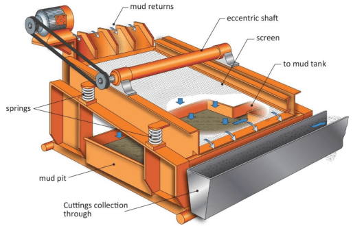
A shale shaker or vibration screen is a spring-mounted screen. The vibration of the such screen is by the rotation of an eccentric shaft mounted on top of the screen frame (Figure 1). We can always use multiple shakers to provide sufficient mud handling capacity. Historically a land rig (also check Drilling Rig Types) would have perhaps two shakers and further use of secondary solids control equipment.
Applications
We can easily observe the shale shaker’s performance, and all aspects of its operation are visible. Shale shakers provide the advantage of not degrading soft or friable cuttings. Shale shakers can produce a relatively dry cuttings discharge when well operated and maintained.
In unweighted muds, the shale shaker’s primary role is to remove as many solids as possible and reduce the solids loading to the downstream hydro-cyclones and centrifuges to improve their efficiency. The shale shaker is the primary solids removal device in muds containing solid weighting agents (Check WBM Additives – OBM Additives) such as barite (barite in drilling). It is usually relied upon to remove all drilled cuttings coarser than the weighting material. Downstream equipment will often remove too much valuable weighting material.
We should install enough shakers to process the total circulating rate to remove as many drilled cuttings ( You may be interested in Unrepresentative drilling cuttings) as economically feasible. Given the importance of the shale shaker, We should select the most efficient shakers and shaker screens to achieve the optimum economic performance of the solids control system.
Shale Shaler Mechanism
Stated that a shale shaker channels mud and solids onto vibrating screens. The drilling mud and fine solids pass through the screens and return to the active system. Solids coarser than the screen openings are conveyed off the screen by the vibratory motion of the shaker. The shaker is the only solids removal device that makes a separation based on physical particle size. Hydrocyclones and centrifuges separate solids based on differences in their relative mass.
Shale Shaker Types
In the oilfield, There are three significant types of shale shakers.
- Single deck shakers
- Differential single-deck shakers
- Double and multiple screen shakers.
Singe Deck Shaker
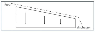
Figure 2 shows a single deck shaker. In the past, most shakers in use were of this type. They had reasonably coarse screens, so only they could remove the coarser formation particles (cuttings, cavings, and coarse sand).In addition, the finer sand and silt remained in the drilling fluid. The other problem with this type of screen was its low efficiency.
Differential single-deck shakers
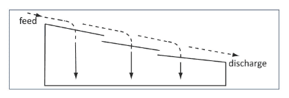
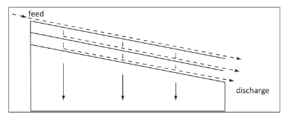
Figure 3 shows the construction of the differential single-deck shaker. The screens are said to be in “parallel,” and the angle of the screen slope varies.
Double-deck Shale shakers
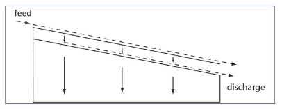
Most modern drilling units now have double-deck shakers fitted. These have a second, finer screen in “series,” which removes most of the finer particles (see Figure 4). The other screen size can be up to 150 mesh (104 μm).
Multiple deck shakers
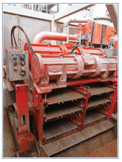
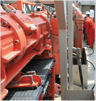
Multiple screen shakers have a single-deck construction with three or four screens placed at different levels in a “series” arrangement. Figures 5 & 6 show this type of arrangement.
Figure 5: Multiple deck shakers
In the types of shale shakers article, we have given more details about its types and applications.
Shale Shakers Performance & Design Characteristics
Performance
Improved shaker efficiency has reduced the load on secondary solids control equipment. Modern systems may now have four or five shakers, especially offshore or when handling large volumes
We can determine the volume of fluid that a shaker can process by the following:
- The size of the openings in the wire screen(s).
- The percentage of open area.
- The speed and amplitude of the vibrations.
- The type of motion (vibrator position).
- Its fluid flow properties.
- The class, size, and amount of solids.
The rate of solids discharge depends on the following:
- The type of motion.
- The speed and amplitude of vibration.
- The mesh design.
- The screen strength.
Design
The characterization of Shale shakers will be through three ways.
- Amplitude and speed
- Motion types
- Slope
The amplitude, or one-half of a stroke of a shaker, is determined by the vibrator’s eccentric weight. Typically, shakers use low amplitudes and high vibrator speeds. Fine screen shakers have high amplitudes at lower rates to prevent plugging of the screens. Vibration speed is essential to remove cuttings from the screen efficiently. Shale shakers are now available with variable speed control.
Most modem shakers use linear motion. Linear motion shakers have the vibrator mounted at the front of the basket through the center of gravity. We can achieve linear motion by using two counter-rotating vibrators/shafts. Because of their positioning and vibration dynamics, they will naturally operate in phase. They are located so that a line drawn from the shaker’s center of gravity bisects at 90°, a line drawn between the two axes of rotation. This design gives a sawtooth-type motion allowing longer residence time on the screen and increased throughput compared to unbalanced and balanced motion-type shakers.
We have discussed the shale shaker design and selection in the previous article.
Estimating The Number Of Shakers Required (Rule Of Thumb)
Base the number of shakers required on the economics and physical constraints of the specific application.
Based on average drilling conditions, We can make a “ballpark” estimate of shaker requirements from the following table. This estimation is very rough and should be used only as a guide.
| GPM / Max Viscosity | 5 cP | 10 cP | 15 cP | 20 cP | 25 cP | 30 cP | 40 cP | 50 cP | 60 cP |
| 300 | 1 | 1 | 1 | 1 | 1 | 1 | 2 | 2 | 2 |
| 400 | 1 | 1 | 1 | 2 | 2 | 2 | 2 | 2 | 2 |
| 500 | 1 | 1 | 2 | 2 | 2 | 2 | 3 | 3 | 3 |
| 600 | 1 | 2 | 2 | 2 | 2 | 3 | 3 | 3 | 3 |
| 700 | 2 | 2 | 2 | 2 | 3 | 3 | 3 | 3 | 4 |
| 800 | 2 | 2 | 2 | 3 | 3 | 3 | 4 | 4 | 4 |
| 900 | 2 | 2 | 3 | 3 | 3 | 4 | 4 | 4 | |
| 1000 | 2 | 2 | 3 | 3 | 4 | 4 | 4 | ||
| 1100 | 3 | 3 | 3 | 4 | 4 | 4 | |||
| 1200 | 3 | 3 | 3 | 4 | 4 | ||||
| 1300 | 3 | 3 | 4 | 4 | |||||
| 1400 | 3 | 3 | 4 |
The guide, however, needs to reflect the performance of the most modern market-leading shale shakers. The Derrick Flo-Line Cleaner 514 will outperform smaller units and allow fewer units to be used with finer screens to produce the same fluid handling ability.
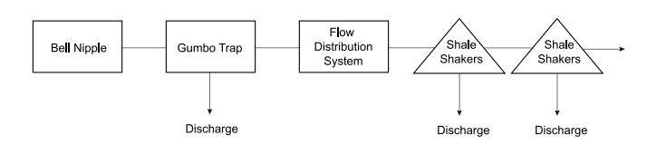
position in the system
Positioned downstream of the gumbo trap and flow distribution system. It may comprise a single set or a dual set, or a cascade system.
setting up Shale Shaker Tips
- Use enough shakers to provide a sufficient non-blanked screen area to run 100 mesh or finer screens. The Shaker setup should adequately process solids-laden fluids at maximum flow rates over any significant hole interval.
- For double-deck shakers, run a coarser screen on top and a finer screen on the bottom. The coarser screen should be at least two meshes coarser. Watch for a torn bottom screen. Replace or patch torn screens at once. Cover 75% to 80% of the bottom screen with mud to maximize the available screen area utilization. Flow back pans are recommended for improving coverage and throughput.
- Try running all the same mesh screens for a single deck shaker with parallel screens. If coarser screens are necessary to prevent mud loss, up to two meshes should be on the shaker at once, with the finer mesh screen closest to the possum belly. The two meshes should have approximately the same size opening. For example, use a combination of 100 mesh (140u) and 80 mesh (178u), not 100 mesh (140u) and 50 mesh (279u). Cover 75% to 80% of the screen area with mud to properly utilize the screen surface area.
Notes
- Use spray bars (mist only) for sticky clay, etc. Use spray bars only with unweighted water-based mud. Many mud companies (List Of 25 Drilling Fluids Companies Data In One Place) don’t recommend spray bars for weighted or oil-based mud.
- Do not bypass or operate with torn screens; these are the leading causes of plugged hydrocyclones. Use screens with mesh backup so they can screen out coarser solids when the finer mesh tears.
- For improved screen life with non-pre-tensioned screens, make sure the components of the screen tensioning system, including any rubber supports, nuts, bolts, springs, etc., are in place and in good shape. Install screens according to the manufacturer’s recommended installation procedure.
- Check the bearing lubrication according to the manufacturer’s maintenance schedule. Lubricate and maintain the unit according to manufacturers’ instructions.
- Rig up with sufficient space and walkways with handrails around the shaker skid to permit easy service. The shaker skid should be level.
- Check for the correct direction of motor rotation for shakers with one vibrator.
- The flow line should enter at the bottom of the possum belly to prevent solids from settling and build-up in the possum belly. If the flow line enters over the top of the possum’s belly, the Rig crew (Drilling Rig Personnel Organization In Oil & Gas) should extend the flow line to within 8 -10 ins (20 – 25 cm) of the bottom of the belly.
- Rig up for equal fluid and solids distribution while utilizing more than one shaker. A cement bypass is desirable.
Shale Shaker Limitations
We consider the shaker limit when large amounts of drilling fluids begin to discharge over the shaker end. We can specify such capacity by interfering with two factors:
- The maximum fluid flow rate handled by the shaker screen is called the fluid limit.
- The solids limit is the maximum amount of solids that screens can separate off the end of the shaker.
Once there is an increase in the number of solids, there will be a reduction in the shaker’s capability to handle such volumes of fluids. Significant factors that affect these limits are:
- Mud Rheology properties (Drilling Mud Properties Guide).
- Wire Wettability: the screen wire shall be oil wet when drilling with oil base mud (Oil Based Mud Systems Benefits & Types). Water adhering to a screen wire lowers the adequate opening size for oil to pass through, so the shaker will not be able to handle the flow of OBM “sheeting”.
- Fluid surface tension: fluids will be challenging to pass through shakers as surface tension increases.
- Fluid Density: adding a weighting agent (solids) to the drilling fluid will increase the density, and further will make it more difficult to screen the drilling mud.
- Quantity of solids
- Solids: Particles slightly larger than the opening size can become wedged in the openings, leading to screen plugging. Also, solids such as gumbo will decrease the effective screen area.
- Hole Cleaning: If cuttings accumulate in the annulus, they will start disintegrating into small solids and increase some PV and solids content over time.
Fluid Only Capacity
Is the shale shaker’s capacity in case no solids are separated by the screens assuming that their volume is small and can pass through? It depends on many factors, such as:
- characteristics of the shaker (“G”-factor, vibrational frequency, type of motion, and angle of the screen deck)
- the screen (area and conductance)
- the fluid properties (density, rheology, additives, and fluid type)
Let’s consider that the screens are porous media so that the fluid capacity will increase as the mud viscosity decreases and the density increases. This capacity increase is because the density will push the fluid to drop through the screens).
Solids Limit
Drilling large diameter holes, sticky formations, and high penetration rates will facilitate reaching this limit quickly.
Final Words
- The shale shaker is the only solids control device that makes a separation based on the physical size of the particle. The opening sizes dictate the separation size in the shaker screens. Hydrocyclones and centrifuges separate solids based on differences between their relative mass and the fluid.
- Most oil and gas companies (100 Oil and Gas Companies List With Top 10) prefer shale shakers with linear vibratory motion for most applications because of their superior processing capacity and fine screening ability. Circular or unbalanced elliptical motion shakers are recommended as scalping shakers in cascading systems.
- The vibration of the shaker basket creates G-forces which help drive shear-thinning fluids such as drilling mud through the screens. Vibration also conveys solids off the screens. Most linear motion shakers operate in the range of 3 to 4 G’s to balance throughput with screen life. G-force is a function of vibration frequency (rpm) and stroke length.
- “High-Speed” should not be equated with “high performance”. Laboratory tests indicate that lower frequency vibration and longer stroke lengths improve throughput capacity in the normal operating range for linear motion shale shakers. Most linear motion shakers operate at 1200 to 1800 rpm.
Hints
- Avoid deck inclinations above 3˚. High deck angles reduce solids conveyance and increase the risk of grinding soft or friable solids through the screens.
- The shaker’s design allows it to accept either hook strips or rigid frame screen panels. Hook strip screen panels are the most common and are usually cheaper, although cuttings’ wetness can be a concern due to deck curvature. Flat, rigid frame panels promote even fluid coverage but can cost more.
- Shakers may have single or tandem screening decks. Single-deck shakers offer mechanical simplicity and full access to the screening surface. We may arrange single deck shakers to process mud sequentially as a “cascading” system to improve performance under high solids loading conditions. Tandem deck shakers offer improved processing capacity under high solids loading conditions when space is limited.
- Manifolds should provide an even distribution of mud and solids to each shaker. Avoid branch tee’s.
- There are operating guidelines for optimizing screen life and cuttings dryness, handling sticky solids, polymer muds, blinding, and LCM problems.
Good for experience