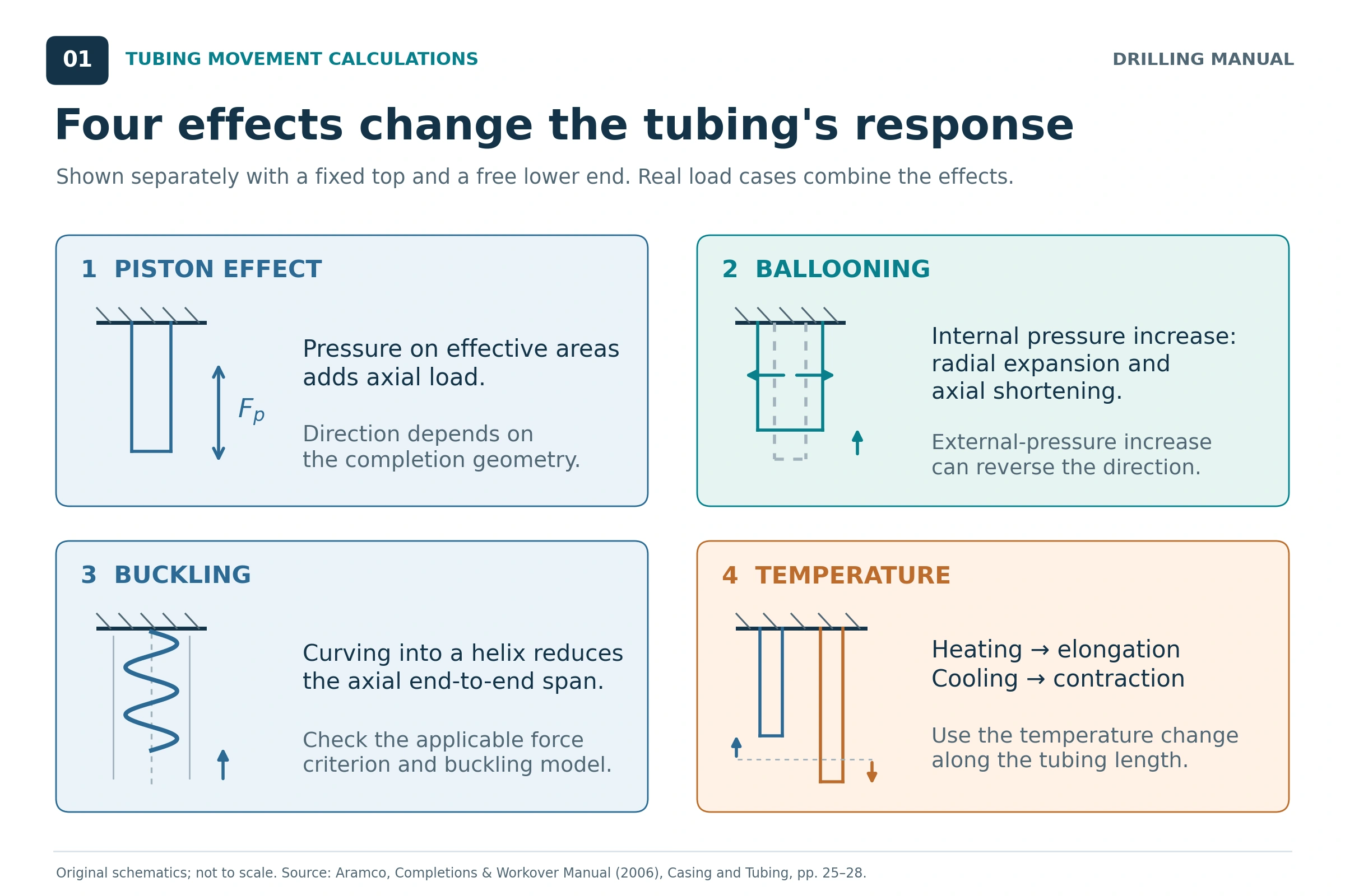
Tubing movement calculations estimate how much a completion string changes its end-to-end length when pressure, temperature or mechanical loading changes. For tubing that can slide through a packer seal bore, the result helps determine the required movement range. For anchored tubing, the same imposed changes can generate additional tubing and packer loads. Establishing the actual restraint is therefore the first calculation step. [1, 2, 3]
This article explains piston, ballooning, buckling and temperature effects using a simplified vertical completion model. It includes an original worked example, applications, factors affecting movement, rules of thumb and limitations. The numerical inputs are hypothetical; they illustrate the calculation method and do not specify operating settings or equipment ratings.
What Is Tubing Movement?
Pressure changes act on tubing end areas and on the pipe wall. Temperature changes expand or contract the steel. Compressive loading can also bend tubing into a helix, reducing its axial reach even though its material length has not shortened by the same amount. These mechanisms can reinforce or oppose one another. [1, 2]
For the freely moving lower end considered here, the total movement is the signed sum:
ΔLtotal = ΔLpiston + ΔLballooning + ΔLbuckling + ΔLtemperature
The calculation concerns completion tubing and its connection to the packer. For background on the equipment, see the guide to production packers. The calculation below uses an idealized single-size string; a more complex completion requires a model that represents its sections and constraints. [1, 2]
Reference and Restraint for Tubing Movement Calculations
Record the Initial Tubing Condition
Tubing movement calculations require a defined reference state for every pressure and temperature change. Record the tubing geometry, fluids, pressure and temperature profiles, seal position, and any applied tension or slack-off at that state. The spaced-out and landed condition is a common reference in the source manuals. A later operating condition must not silently replace it. [1, 2]
ΔP = Pfinal − Pinitial; ΔT = Tfinal − Tinitial
Packer setting and space-out matter because setting pressure, subsequent pressure release, and the installed mechanical load can affect the starting condition. The worked example assumes no initial slack-off and no initial buckling. [1, 2]
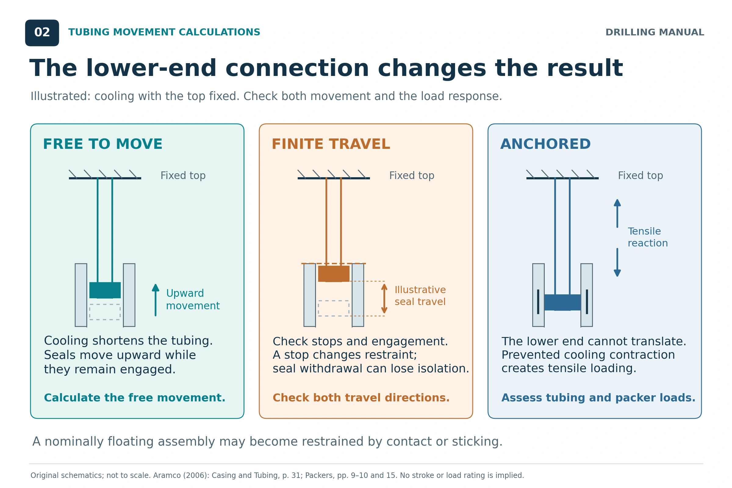
Free, Limited and Anchored Tubing Movement
| Connection condition | How the tubing responds | What the calculation must establish |
|---|---|---|
| Free to slide within its available range | The lower end can move while the seal assembly remains engaged. | Upward and downward movement relative to the installed seal position. |
| Movement limited by a locator or stop | The tubing can move in an allowed direction until it reaches the restriction. | Movement before contact and the additional load after contact. |
| Anchored or latched | The connection prevents the free movement assumed in the movement sum. | Tubing stress and connection/packer reaction, including buckling where applicable. |
A permanent packer can use different tubing connections. An anchor assembly and a sliding locator assembly do not impose the same restraint. Similarly, a polished bore receptacle arrangement must be assessed according to its actual connection and available travel. The equipment name alone does not define the boundary condition. [1, 2, 3]
Inputs, Units and Signs for Tubing Movement Calculations
The equations below use a consistent inch–lbf–psi basis. Length changes are calculated in inches and converted to feet only at the end. In particular, the buckling equation requires effective weight in lbf/in on this basis. [1; units restated consistently]
| Symbol | Meaning | Unit used here |
|---|---|---|
| L | Tubing length between the fixed upper end and the lower connection | in |
| Do, Di | Tubing outside and inside diameters | in |
| Ao, Ai | Areas enclosed by the tubing OD and ID | in² |
| As | Steel cross-sectional area, Ao − Ai | in² |
| Ap | Packer seal-bore area for the modeled piston arrangement | in² |
| E, ν, α | Young’s modulus, Poisson’s ratio and thermal-expansion coefficient | psi; dimensionless; per °F |
| ΔPi,p, ΔPo,p | Internal and external pressure changes at the packer | psi |
| ΔPi,avg, ΔPo,avg | Average internal and external pressure changes along the tubing | psi |
| ΔTavg | Average change in tubing temperature along its length | °F |
| r, I, w | Radial clearance, tubing area moment of inertia, effective weight per unit length | in; in⁴; lbf/in |
Positive movement means elongation, or downward movement of the lower end when the upper end is fixed. Negative movement means shortening, or upward movement. Pressure and temperature changes are positive for an increase. The force symbols Fp and Fb below are positive in compression. [1, 2]
Do not substitute tubing surface pressure for packer-depth pressure without calculating the pressure profile. Likewise, do not use the packer pressure as the average pressure along the full string. The hydrostatic pressure calculation is useful background when preparing the pressure inputs. [1, 2]
The Four Tubing Movement Calculations
1. Piston Effect on Tubing Movement
The piston effect comes from changes in pressure acting on the applicable areas at the tubing–packer connection. For the seal-bore geometry represented in the source manual, the change in compressive piston force is: [1, Eq. 7.B; 2]
Fp = (Ap − Ai)ΔPi,p − (Ap − Ao)ΔPo,p
ΔLpiston = −FpL / (EAs)
A positive Fp produces shortening under this sign convention. A negative value produces elongation. The direction depends on the pressure changes and effective areas: a larger seal-bore area changes the pressure force, and a different connection arrangement may require a different force balance. Do not assume that every increase in tubing pressure produces the same total movement. [1, 2]
2. Ballooning and Reverse Ballooning
Pressure acting on the pipe wall produces radial deformation and a corresponding axial strain through Poisson’s effect. Holding the other terms fixed, increased average internal pressure produces the shortening contribution called ballooning. Increased average external pressure produces the lengthening contribution commonly called reverse ballooning. [1, 2]
The ballooning expression used in tubing movement calculations can be written in area form:
ΔLballooning = −[2νL / (EAs)] × (AiΔPi,avg − AoΔPo,avg)
This is algebraically equivalent to the manual’s diameter-ratio expression, using R = Do/Di. It uses average pressure changes along the string, whereas the piston equation uses pressure changes at the packer. [1, Eq. 7.J; 2]
If the pressure-change profile is linear, its length average is the mean of the top and bottom values. If the profile has distinct sections, calculate appropriate section averages instead of forcing a single top-to-bottom average onto it. [1, Eqs. 7.K–7.L; 2]
3. Tubing Shortening from Helical Buckling
Helical buckling reduces the axial distance between the tubing ends. The compression governing this geometry includes pressure effects and is not simply the piston-force change. In the ideal free-seal arrangement with no additional applied end load, the source manual gives the effective buckling force as: [1, Eqs. 7.F–7.I]
Fb = Ap(Pi,p − Po,p)
Here Pi,p and Po,p are pressures in the state being assessed. When the reference state has equal internal and external pressure at the packer, zero initial buckling and no added end load, the final force is also Ap(ΔPi,p − ΔPo,p). These restrictions matter: the pressure difference alone is not a general buckling criterion for every completion. [1]
For a vertical uniform string with positive effective weight w:
n = Fb/w; r = (casing ID − Do)/2; I = π(Do⁴ − Di⁴)/64
The distance n is measured upward from the bottom to the ideal neutral point. If Fb > 0 and n ≤ L, the source’s partially buckled-string expression is: [1, Eqs. 7.C–7.D]
B(Fb) = −Fb²r² / (8EIw)
If n > L, the whole modeled length is within the buckled interval. The corresponding expression is: [1, Eq. 7.E, algebraically rearranged]
B(Fb) = −[r² / (8EIw)] × [Fb² − (Fb − wL)²]
For Fb ≤ 0, B is zero in this ideal model. The movement contribution between two states is ΔLbuckling = Bfinal − Binitial. Consequently, the appearance of buckling shortens the string, while removal of pre-existing buckling can restore axial reach. Do not square a pressure change and call it the incremental shortening when the initial string was already buckled. [1; state-to-state interpretation of the source equations]
The effective weight w includes steel and internal fluid weight, less the weight of external fluid displaced by the tubing OD. It is not automatically the tubing’s nominal weight in air. A change in fluids can change w as well as the pressure profiles. [1, 2]
4. Tubing Movement from Temperature Changes
For a uniform material, the freely moving tubing’s thermal length change is: [1, Eq. 7.M; 2]
ΔLtemperature = αLΔTavg
Heating gives elongation; cooling gives contraction. Use the average change in the tubing’s temperature along the length being analyzed. The surface-fluid temperature change alone does not describe that distribution. A top-and-bottom average represents a linear temperature-change profile; a section-based calculation is preferable when the profile is not linear. [1, Eqs. 7.M–7.N; 2]
The numerical example uses E = 30 × 10⁶ psi, ν = 0.30 and α = 6.9 × 10⁻⁶ per °F, values stated in the cited manual. These are the calculation constants for this example; a design model must use properties appropriate to its actual material and conditions. [1, 2]
Tubing Movement Calculations: Worked Example
Assumptions for the Tubing Movement Example
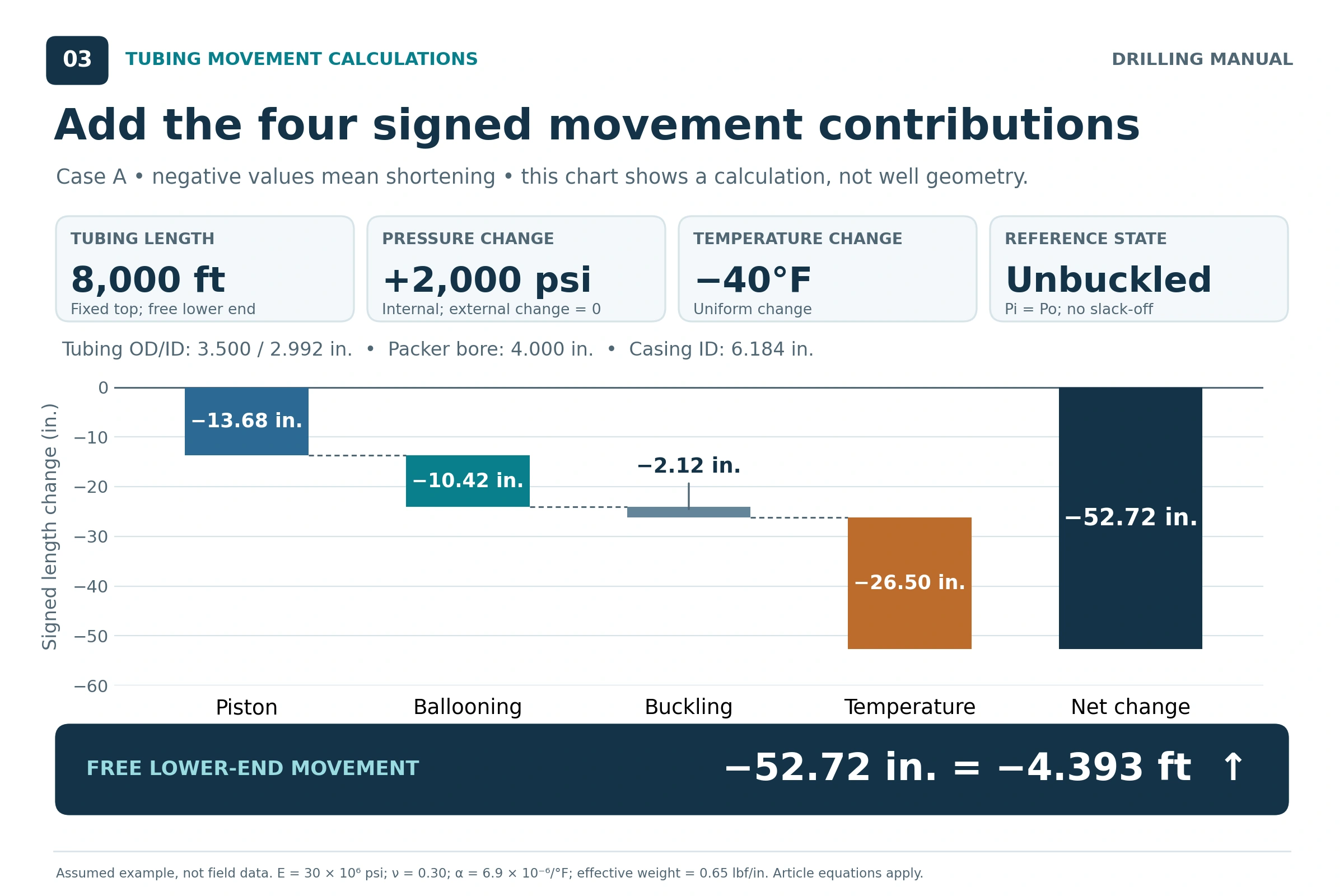
Consider an ideal vertical, uniform tubing string with its upper end fixed and its lower seal assembly free to slide throughout the calculated range. Initially the tubing and annulus pressures are equal, and the string has no initial buckling or applied slack-off. This is an original illustrative case, not a field record or a copied manual example.
| Input | Assumed value |
|---|---|
| Tubing length | 8,000 ft = 96,000 in |
| Tubing OD / ID | 3.500 / 2.992 in |
| Packer seal-bore diameter | 4.000 in |
| Casing ID | 6.184 in |
| Effective weight w | 0.650 lbf/in = 7.800 lbf/ft, already accounting for fluids |
| E / ν / α | 30,000,000 psi / 0.30 / 6.9 × 10⁻⁶ per °F |
| Internal pressure change | +2,000 psi uniformly along the tubing |
| External pressure change | 0 psi |
| Tubing temperature change | −40°F uniformly along the tubing |
Uniform changes make the packer-depth and average pressure changes equal in this example. The case also assumes no change in effective weight. Those simplifications must not be transferred automatically to a real stimulation or production profile.
Step 1: Calculate Areas and Clearance
Using A = πD²/4 gives Ai = 7.03093 in², Ao = 9.62113 in², As = 2.59019 in² and Ap = 12.56637 in². The radial clearance is r = 1.342 in, and I = 3.43234 in⁴.
Step 2: Calculate Piston and Ballooning Contributions
The compressive piston-force change is:
Fp = (12.56637 − 7.03093) × 2,000 = 11,070.87 lbf
ΔLpiston = −13.6773 in
Using the same 2,000 psi as the average internal pressure change, with zero external change:
ΔLballooning = −10.4235 in
Step 3: Check the Buckling Branch
The effective compressive force is Fb = 12.56637 × 2,000 = 25,132.74 lbf. It differs from the 11,070.87 lbf piston-force change because the pressure effects relevant to buckling are included.
n = 25,132.74 / 0.650 = 38,665.76 in = 3,222.15 ft
Since 3,222.15 ft is less than the 8,000 ft string length, the partially buckled expression applies. The initial buckling term is zero.
ΔLbuckling = −2.1246 in
Step 4: Calculate Thermal Movement and Add the Terms
ΔLtemperature = 6.9 × 10⁻⁶ × 96,000 × (−40) = −26.4960 in
| Contribution | Movement, in | Direction in this case |
|---|---|---|
| Piston | −13.6773 | Shortening |
| Ballooning | −10.4235 | Shortening |
| Buckling | −2.1246 | Shortening |
| Temperature | −26.4960 | Shortening |
| Total | −52.7213 | 4.3934 ft upward at the lower end |
The total is calculated from unrounded component values. Thermal contraction is the largest contribution in this particular case. A different pressure profile, geometry or temperature change can produce a different balance.
From Tubing Movement to Required Seal Travel
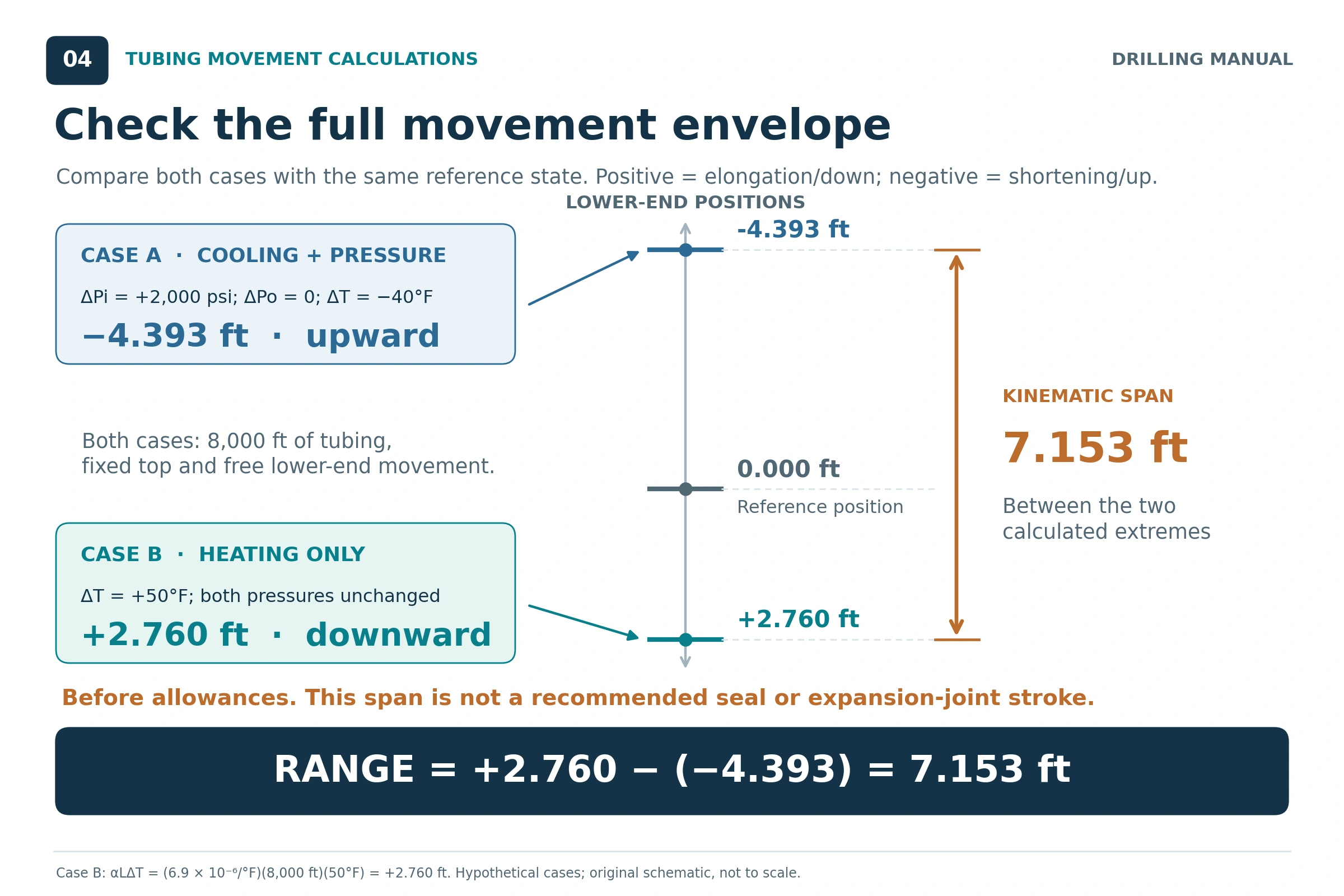
One operating case does not define the complete travel requirement. Repeat tubing movement calculations for each relevant operating state, using the same reference. The useful result is an envelope showing the largest upward and downward displacement, together with the installed seal position. [1, 2, 3]
As a second, separate hypothetical case, keep the example’s pressures unchanged from the reference state and increase the tubing temperature uniformly by 50°F. With no added buckling in the freely moving model, the thermal movement is +33.1200 in, or +2.7600 ft.
The two illustrative cases span:
Movement span = +2.7600 − (−4.3934) = 7.1534 ft
This is the calculated separation between two positions. It is not a seal assembly length or a device recommendation. The actual arrangement must provide sufficient travel on each side of its installed position while retaining the required seal engagement, allowing for applicable tolerances and covering the other design cases. A nominal stroke length alone does not establish that the starting position works. [1, 3]
Details of permanent-packer seal assemblies help explain how the selected hardware accommodates movement. The calculation and the equipment geometry must be checked together.
Tubing Movement and Loads in Restrained Strings
If the lower end is anchored, a free-movement result does not become an actual seal displacement. Restraint develops reaction loads, and the pressure, thermal and buckling responses must satisfy the constrained geometry. Reaching a travel stop changes a previously free-moving case into a restrained one. [1, 3]
A useful limited illustration is thermal change alone in a straight, uniform, elastic string held at both ends. With ΔN defined positive in tension, the incremental axial reaction is:
ΔN = −EAsαΔT
For the example’s area and a uniform 40°F cooling, this thermal-only model gives +21,447 lbf in tension, rounded to the nearest pound. This is a derivation from thermal expansion and Hooke’s law. It is not the full packer load for the combined pressure-and-cooling example. [1, §7.6; calculation derived here]
The source manual treats the general restrained case as nonlinear when helical buckling contributes. Multiplying the entire free-movement total by EAs/L can therefore give a misleading answer. The model must account for the actual restraint, initial load, pressure effects and buckling response. [1]
Applications of Tubing Movement Calculations
- Seal travel and space-out: compare movement in both directions with available travel and retained seal engagement.
- Completion and packer selection: decide whether an anchored connection or a suitable movement-accommodation arrangement fits the predicted load cases.
- Pressure testing: assess the pressure-induced changes associated with tubing and annulus tests, including the reference condition after setting.
- Injection and stimulation: examine combined pressure changes and cooling, which can act together to shorten tubing.
- Production and shut-in: compare changes in pressure and temperature profiles, including states where pressure changes faster than tubing temperature.
- Intervention planning: assess changed fluids, mechanical loads or a seal assembly that may no longer move as originally intended.
These are load-case and equipment checks within the wider completion design. The packer selection guide provides the related equipment context. [1, §§7.6–7.7; 2; 3]
Factors Affecting Tubing Movement
| Factor | Why it matters |
|---|---|
| Length | Piston, ballooning and thermal movements scale with the analyzed length in the uniform-string expressions. |
| Tubing OD, ID and wall area | They determine pressure areas, axial stiffness and bending stiffness. |
| Seal-bore area | It changes the pressure-induced piston force and the effective buckling force in the modeled arrangement. |
| Casing-to-tubing clearance | The simple buckling-shortening term contains the square of radial clearance. |
| Pressure distribution and fluid changes | Packer-depth pressures, average pressures and effective weight can all change. |
| Temperature distribution | Movement depends on the average change along the string; separate sections may respond differently. |
| Initial tension, slack-off and buckling | These change the reference state and the subsequent force/movement response. |
| Restraint, friction and well geometry | The actual ability to move and the suitability of the simplified vertical model depend on these conditions. |
Tubing movement calculations depend on the geometry and loading conditions represented in the source equations. They should be evaluated together; changing one input can alter more than one contribution. [1, 2, 3]
Rules of Thumb for Tubing Movement Calculations
- Keep the reference state visible. Write down the initial and final conditions before subtracting pressure or temperature values. Include the installed mechanical load and seal position.
- Separate local pressure from average pressure. Use packer-depth changes for piston loading and length-average changes for ballooning.
- Use the thermal scaling check. With α = 6.9 × 10⁻⁶ per °F, a uniform 10°F change gives approximately 0.83 in of free thermal movement per 1,000 ft. This is a derived check on the thermal term only.
- Convert weight per length before calculating buckling. Divide lbf/ft by 12 to obtain lbf/in for the inch-based equation used here.
- Check the neutral point. Confirm whether Fb/w lies within the string before choosing the partial-length or full-length buckling expression.
- Keep the signs through the sum. Opposing contributions can give a small net movement even when individual effects are substantial.
- Check both directions and the starting position. Sufficient total nominal stroke does not prove sufficient upward and downward travel from the installed position.
- Treat a travel stop as a change of restraint. Once contact occurs, continue with a load analysis appropriate to that condition.
These are calculation checks derived from the cited references. They do not establish a universal allowable movement, safety factor, pressure limit or seal-engagement allowance. [1, 2, 3]
Limitations of Simplified Tubing Movement Calculations
Geometry: the worked example assumes a vertical, uniform string and casing. Tapered strings, multiple casing IDs, multiple packers and significant deviation require section and constraint treatment appropriate to the completion. [1, 2]
Pressure and temperature profiles: simple top-and-bottom averages represent linear change profiles. They can miss localized cooling or other nonuniform changes. The highest pressure and greatest cooling need not occur at the same time, so distinct operating states may control different checks. [1]
Buckling assumptions: the closed-form expressions use an idealized vertical geometry, positive effective weight and the specified loading. Initial buckling, mechanical preload, contact and friction cannot be represented merely by inserting a pressure difference into the worked example. [1, 2]
Elastic response: the equations use elastic deformation. They do not describe permanent deformation after the material’s elastic range has been exceeded. [1]
Integrity and equipment capacity: a movement calculation does not establish acceptable combined stress, burst or collapse resistance, connection capacity, packer rating or seal performance. Those are additional design checks. [1, 2, 3]
Actual movement availability: a nominally sliding assembly may have limited travel, contact a stop, or become stuck. The calculation must reflect the condition that can actually occur. [1, 2, 3]
Tubing Movement Calculation Workflow
- Define the installed reference state and the operating states to assess.
- Identify the tubing–packer connection, installed seal position and available travel in each direction.
- Build pressure and temperature profiles for each state, with the actual fluid and geometry inputs.
- Calculate piston, ballooning, thermal and buckling contributions using consistent units and the appropriate model branch.
- Sum the signed contributions for each free-movement case and establish the movement envelope.
- Identify stop contact or anchored cases, then solve the corresponding restrained-load problem.
- Check seal engagement, component loads and tubing integrity before accepting the completion arrangement.
This workflow organizes tubing movement calculations using the methods described in the references. It does not replace the separate equipment and stress checks needed for a specific completion. [1, 2, 3]
Frequently Asked Questions About Tubing Movement
Does Increasing Tubing Pressure Always Shorten the String?
No. Increased average internal pressure gives a shortening ballooning contribution in this model, but piston movement depends on effective areas and pressure changes. Thermal movement, restraint and the initial buckling state also affect the result. Calculate the contributions and their signed sum. [1, 2]
Can Tubing Movement Be Small While Loads Are Significant?
Yes. Tubing movement calculations can give a small net result when individual contributions oppose each other. Anchored tubing can carry additional load while its ends remain fixed. A small movement total does not establish a small stress change or acceptable equipment loading. [1, 2, 3]
Does a Permanent Packer Mean the Tubing Is Anchored?
No. The tubing may use an anchoring assembly or a locator assembly that allows sliding within a limited range. The installed connection determines the constraint used in the calculation. [3]
Which Pressure Should Be Used for Piston and Ballooning?
Use internal and external pressure changes at the packer for the piston expression. Use their average changes along the analyzed tubing length for ballooning. They are equal only in special cases such as the uniform pressure step chosen for this example. [1, 2]
Can Free Movement Be Converted Directly Into Packer Load?
A simple elastic conversion can represent a restricted linear case, such as thermal change alone in a straight uniform string. A combined pressure, thermal and buckling case generally requires a constrained force–displacement analysis. The source manual specifically identifies the nonlinear effect of helical buckling. [1]
References
- ENI S.p.A., Agip Division. Completion Design Manual, STAP-P-1-M-7100, Revision 0. Chapter 7, especially pp. 154–177: elastic behavior, tubing movement and restraint, pressure effects, temperature effects and operating load cases.
- Saudi Aramco. Completions & Workover Manual, September 2006. “Casing and Tubing,” pp. 24–28 and 31–38; “Packers,” pp. 9–10 and 14–15. Used for technical principles and definitions, not as a statement of current company requirements.
- Perrin, Denis, with Michel Caron and Georges Gaillot. Well Completion and Servicing. Éditions Technip, 1999. Sections 3.3.2.2, 3.4.2 and 3.4.4.4, especially pp. 130, 132, 135 and 138: load cases, tubing–packer restraint and seal travel.
The worked examples and diagrams are original. Equations are restated in a consistent unit system, with algebraic rearrangements and derived checks identified in the text.