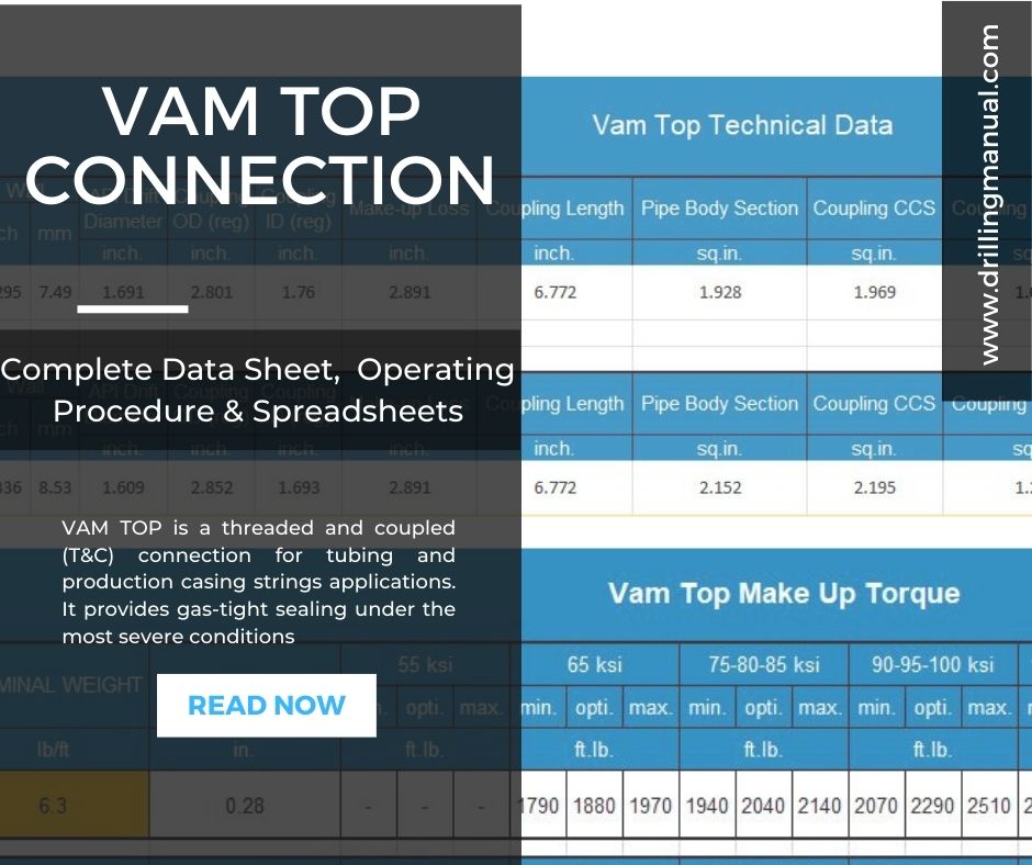
First of all this VAM TOP is one of Vallouric Company products, and we are not an agent to them or selling any of their product. VAM TOP is a threaded and coupled (T&C) connection for tubing and casing string types. It provides gas-tight sealing under the most severe conditions: VAM TOP thread minimizes the risks that result from combined loads induced by: gas pressure, temperature, bending, and compression. VAM TOP product line covers a wide range of diameters and wall thicknesses, for API material as well as for proprietary corrosion-resistant material (Sour Service and CRA materials).
Such connection is globally recognized as the industry reference for premium connections (it has extensive testing and wide use). VAM TOP’s track record stretches back over more than a decade. VAM TOP is available to you, wherever you are (connections and accessories are supported throughout the world by the VAM licensee network managed by VAM Services) (check also: Buttress connection)
Casing & Tubing Vam Top Connections Sizes
- VAM TOP Casing 5” to 16”
- VAM TOP Tubing from 2 3/8”
- VAM TOP HT (High Torque) 4 1/2” to 7”
- VAM TOP HC (High Compression) 4 1/2” to 7”
Vam Top Threads Features
Optimized Metal-to-Metal Seal
VAM TOP metal-to-metal seal connection was optimized to improve sealability performances while preventing from any galling issues. Sealing integrity remains constant despite repeated makeup and break-out, and combined loads cycling. The performances of the metal-to-metal seal have been validated through more than 120 qualification tests under the most demanding testing procedures.
Reverse Angle Torque Shoulder
The torque shoulder provides a positive torque stop which allows accurate power-tight make-up and minimizes hoop stresses in the connection. The wedge effect caused by the reverse angle gives the connection superior structural strength and energizes the metal-to-metal seal contact.
Hook thread profile:
VAM TOP thread includes a negative load flank of -3°. This specific feature provides, in addition to an improved tensile resistance, higher performances under external pressure, compression, and bending. Optimized thread geometry also minimizes the risk of galling even when thread lubricants are poorly applied.
| 2 3/8″ – 2 7/8″ | 3 1/2″ – 4 1/2″ | 5″ – 7 5/8″ | 8 5/8″ and above | |
| Thread Per Inch (TPI) | 8 TPI | 6 TPI | 5 TPI | 4 TPI |
Vam Top Connection Benefits
- Excellent gas-tight sealing under combined loads
- Excellent resistance to bending, compression, and torque
- Excellent resistance to external pressure and compression
- Easy to use and repair
Vam Top Connection Seal
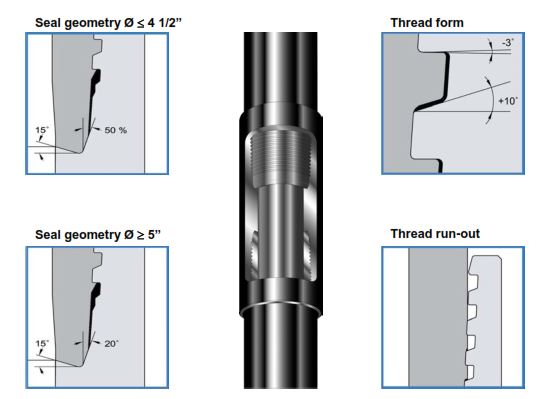
A newly patented angle metal-to-metal seal system offers from 2 3/8” to 14” excellent gas-tight sealing even under the most severe combined loads, as encountered in deviated or long horizontal well applications. Sealing integrity remains constant despite repeated make-ups and break-out. Seal geometry protects against galling.
Shoulder
A reverse angle torque shoulder provides a positive torque stop, which allows for accurate power-tight make-up and minimizes hoop stresses in the connection.
The wedge effect caused by the reverse angle gives the connection superior structural strength. The shoulder design was optimized in order to resist adverse conditions such as combined compression and external pressure or combined bending, compression, and torque.
Vam Top Thread Design
A modified hook thread profile, with a -3° reverse angle on the load flank not only provides the Vam Top connection with superior tensile strength but also increases its resistance to compression. The excellent structural strength including the increased bending and compression resistance makes this connection especially useful in highly deviated and long horizontal wells. Optimized thread geometry minimizes the risk of galling even when thread lubricants are poorly applied.
Coupling
Coverage of the vanishing threads, long internal shoulder, and coupling critical cross sections greater than those of the pipe body, contribute to a high-performance, 100% efficient connection.
Internal profile
A 6° weight bore chamfer, tight tolerances on the coupling center and a long shoulder combine to minimize turbulence and energy loss inside the connection for the high-velocity gas flows encountered.
Options
VAM TOP SC90 / VAM TOP SC8O (Special clearance): these extra-clearance couplings offer 90% and 80% tensile efficiency respectively.
Thread compound volumes
The minimum volume of the compound should be shared between the pin and box ends as follows:
- 2/3 on box (never leave the box without any dope)
- 1/3 on pin
Thread compound should be applied evenly in order to get a uniform coating on all parts of the connection. If a compound applicator is used for the box end it shall be adjusted to apply the below-recommended volume of thread compound.
Running VAM TOP Connection – Dope Quantities
| Nominal OD (in.) | Weight (lb.ft.) | Dope volume (cm3) | Dope volume (in3) |
| 2 3/8 | 4.6 & 5.1 | 2 | 0.1 |
| 2 3/8 | 5.8 to 7.35 | 3 | 0.2 |
| 2 7/8 | 6.4 | 3 | 0.2 |
| 2 7/8 | 7.8 to 10.7 | 4 | 0.2 |
| 2 7/8 | 11.5 | 5 | 0.3 |
| 3 1/2 | 6.5 to 10.2 | 4 | 0.2 |
| 3 1/2 | 12.7 to 14.7 | 6 | 0.4 |
| 3 1/2 | 15.7 to 18.35 | 7 | 0.4 |
| 4 | 8.2 to 13.2 | 5 | 0.3 |
| 4 | 14.8 to 16.5 | 7 | 0.4 |
| 4 | 18.9 & 22.2 | 8 | 0.5 |
| 4 1/2 | 10.5 to 15.1 | 6 | 0.4 |
| 4 1/2 | 17 to 18.9 | 8 | 0.5 |
| 4 1/2 | 21.5 & 23.7 | 9 | 0.5 |
| 5 | 14 | 0.9 | |
| 5 1/2 | 16 | 1 | |
| 5 3/4 | 17 | 1.1 | |
| 6 5/8 | 19 | 1.2 | |
| 7 | 25 | 1.5 | |
| 7 5/8 | 27 | 1.7 | |
| 7 ¾ | 28 | 1.7 | |
| 8 5/8 | 37 | 2.3 | |
| 9 5/8 | 41 | 2.5 | |
| 9 7/8 | 43 | 2.6 | |
| 10 | 44 | 2.7 | |
| 10 ¾ | 46 | 2.8 | |
| 10 7/8 | 50 | 3.05 | |
| 11 ¾ | 59 | 3.6 | |
| 11 7/8 | 60 | 3.6 | |
| 13 3/8 | 67 | 4.1 | |
| 14 | 70 | 4.3 | |
| 15 | 78 | 4.8 | |
| 16 | 84 | 5.2 |
VAM TOP Connection Technical Data
Download The Excel Version
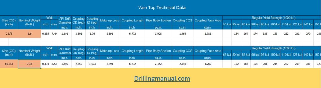
In this version, all you have to do is to write down the size and the nominal weight and it will get the technical data that you want for the Vam Top thread.
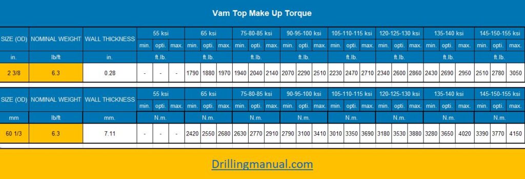
Vam Top Connection Make-Up Torque Tables
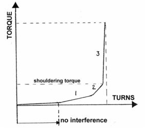
The torque/turn graph has a different shape for other VAM connections. It has three separate slopes:
- First slope = thread interference.
- Second slope = seal interference.
- Third slope = torque applied.
The reference torque is at ≤ 5% of the optimum torque. Reference can increase if required during running (casing running, Liner running), the scale of the torque/turn graph should be set at a suitable range in order that a clear graph profile can be analyzed. If the turning scale is set to high you will not be able to see a clear transition of seal interference to the shoulder point. If set at an appropriate level, about 2 turns should be efficient to enable the engineer to see a clear graph profile from which the engineer should be able to determine if the graph is acceptable or not.
Note: to obtain a clear graph with three distinct slopes, it may be necessary to adjust the scale of the graph. If non-linearity is observed, the make-up should not be stopped at the point of non-linearity but should continue till the aim torque has been achieved. Thereafter the connection should be broken out fully and inspected. If there is no evidence of over torque, the connection can be re-run. A second “string failure” will result in the pin and box being laid down and replaced.
Download Excel Version For Make-Up Torque
In this Spreadsheet, you will just write the size and nominal weight. Then all the white cells will get you all the data you need.