What Is Liner Hanger System?
As we mention in the Casing Liner article, a Liner is a casing string that does not reach the surface. We can use liner hanger system assembly to support & hinge the casing liner on the previous casing string in oil and gas drilling wells. ( Check Types Of Casing Article) .
In general, there are many reasons to choose to use a casing liner hanger. As it is much cheaper than running casing (especially in deep oil and gas wells). However, liner hanger systems have two main types: mechanical set & hydraulic set liner hangers. We can still sort it by other features or abilities. Now, our objective in this article is to understand the following:
- Applications
- Types
- Components
- Rating
We believe that the following articles will help you a lot much more understanding of liner hanger system assembly:
- Casing Liner Types & Application
- Mechanical Set Liner Hanger
- Hydraulic Liner Hanger
- Liner Hanger Running, Setting, Cementing Procedure
What Are The Main Applications Of Liner Hangers?
- Case off open hole more rapidly and efficiently.
- Complete oil and gas wells with less weight landed on the wellhead.
- Provide improved cement jobs.
- Liner Hanger Provides good well control while drilling and completing oil & gas wells.
- Good economics – cheaper to suspend casing from the bottom of an existing liner than to run casing to the surface. It also prevents the casing from buckling under its weight if set on the bottom.
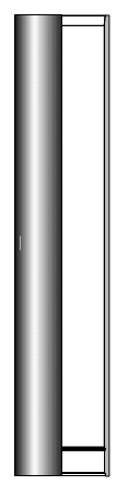
Liner Hanger Assembly Components
In general, liner hanger system components are:
- Liner-top polished bore receptacle (PBR), also known as a tie-back sleeve or tie-back extension
- The liner-top packer or liner-setting sleeve
- Setting Sleeve
- Casing Liner hanger
- Cement displacement system (cementing pack off, CMT wiper plug, drill pipe dart, and landing collar)
- Seal Nipple & its Packers
- Liner Hanger Running Tools
- Setting Collars, Top Set couplings, or Running Subs – Liner Carrying Mechanism
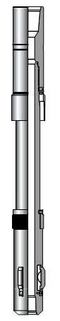
Tie Back Seal Receptacle, Tie Back Sleeve, or Tie Back Extension
A tie-back seal receptacle is a seal-bore receptacle that we can install it at the top of a liner assembly. It provides a means to extend the existing liner to a point further up the hole. We can also install the tie-back receptacle in conjunction with related equipment such as hangers, liner packers, or setting collars. Its manufacturing process is typically from the same grade of steel as the casing and the liner assembly components.
Popular tools datasheets & catalogues in the market: Schl. MatchSet™ Tieback Receptacle, Product Sheet Liner Hanger with Metal-to-Metal Tieback, Weatherford TSP4L Tieback Polished-Bore Receptacle (PBR)
Liner Top Packers Or Setting Sleeve
All liners consist of either a liner-top packer or a liner setting sleeve, which connects the liner to the running tool. The main application of liner-top packers and most setting sleeves is the conjunction with a tie-back polish bore receptacle (PBR).
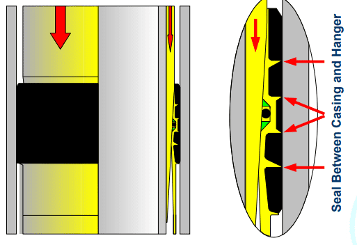
Liner Top Packers
A variety of liner packers are available for use in liner installations. Depending on the application, the utilization of a liner packer can be instead of a hanger as a stand-alone component of the liner assembly. Or incorporated in the design of the overall liner assembly. Regardless of its design, a liner packer provides a seal between the liner top and the supporting casing. In fact, the common name of liner packers is liner top packers.
For many reasons, the primary purpose of using liner-top packers is to isolate the liner top after setting & cementing operations of the liner hangers. Below we are explaining the 5 significant purposes of liner top packers:
- First, Isolation of formation pressure below the liner-top from the casing ID above
- Second, Isolation of treating pressures below the liner-top during fracture or acid work
- Third, Isolation of formation fluids while the cement sets, helping to stop gas migration
- Forth, Isolation of lost-circulation zones
- Fifth, The only isolation above the production zone in uncemented liners
Liner packers incorporate a variety of different element systems designs. One can energize the element system by applying a compressive force on the element system, most often by using the mass of the drill pipe. Commonly, using a hydraulic setting tool in horizontal oil and gas wells generates sufficient force to mechanically activate the setting mechanism of the casing liner hanger packer and energize the element system.
We can always use the liner-top packer as a tie-back completion or production packer.
Popular Liner Top Packer datasheets & catalogs in the market: Liner Top Packers | Baker Hughes, Liner Top Packer – DEW GmbH, High-Pressure Liner-Top Packer – Weatherford, LX Liner Top Packer – TIW
Setting Sleeves
We can say that a liner setting sleeve is an alternative to a liner-top packer and provides how the running tool deploys the liner. A PBR will help tie the liner back to the surface with a tie-back packer or scab liner.
- It is where the liner string and drill string connection are provided.
- Each sleeve is connected with the appropriate setting tool
Popular running setting sleeves datasheet & catalogs in the market: Setting Sleeve – DEW GmbH, Weatherford Setting Sleeve, Halliburton MatchSet™ Hydraulic-Release Setting Sleeve for Liner Hanger
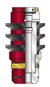
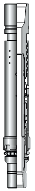
Liner Hanger
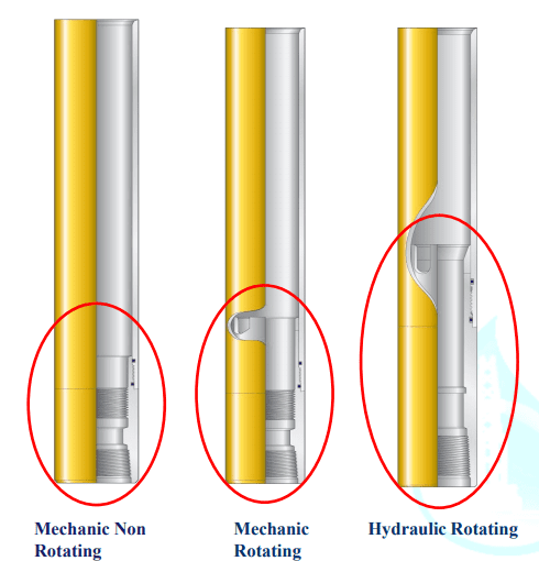
Setting a Liner Hanger system can be in place in one of two methods: Mechanical Set or Hydraulic Set.
Mechanical Set Casing Liner Hanger Type
A mechanical liner hanger is set by string manipulation. The simplest mechanical liner hanger setting feature is a J mechanism. This design is easy to operate and reliably sets the hanger: you easily pick it up and rotate it in the setting direction (usually right); you can slack down the weight on the hanger to set it.
The main advantage of mechanical liner hangers over hydraulic models is the absence of a port in the body to transmit setting pressure.
The main disadvantage of mechanical liner hanger is that deploying them to the bottom and in deviated and/or extremely deep oil and gas wells can be difficult. With mechanical liner hangers, manipulating the liner with the drilling pipe (check also: API Drill Pipe Specifications) through tight spots and setting it are difficult tasks.
Rotation while running in the hole can be problematic and can damage the setting mechanism (drag spring). In addition, setting mechanical liner hangers is difficult—if not impossible—should the liner become stuck. (Check also: Stuck Pipe Full Guide).
Hydraulic Set Casing Liner Hanger Type
The mechanism of setting a hydraulic liner hanger is by applying differential pressure across the hydraulic cylinder in the liner hanger. To prevent the hanger from pre-setting during deployment, the hydraulic cylinder is shear-pinned in place. Usually, we adjust the value of the maximum circulating pressure before the hanger to be 50 percent of this setting pressure.
A typical setting procedure for a hydraulic liner hanger requires dropping a ball, landing the ball on a seat in the landing collar, pressuring up against it to activate the liner hanger (a hydraulic piston move the slips up the cone ramps and sets the slips in the existing liner), and then slacking down weight on the liner hanger.
The main advantage of hydraulic liner hanger over mechanical models is that we can set them in high-angle and/or extremely deep drilling oil and gas wells because drill string or liner manipulation is not required to activate them. Unlike mechanical models, hydraulic liner hangers do not feature drag springs; therefore, we have the ability to rotate and reciprocate to the bottom with the correct running tools.
Other Types
As mentioned above most liner hangers can be categorized by their setting mechanism, which is either hydraulic or mechanical. Hangers can be further defined by other features or abilities, such as the number of cones and the ability to rotate after the hanger has been set.
Cones.
In general, a greater number of cones means increased hanging capacity, but it also means longer and more expensive assemblies.
Liner system design takes into account more parameters than hanging capacity such as additional loads applied to the liner hanger. A 7-in. liner hanger that can accommodate an 800,000-lbf (3,559-kN) load in 9 5/8-in., 47-lb/ft N-80 casing may carry 7-in. 29-lb/ft L-80 pipe that is only good for 676,000-lbf (3,007-kN). You may need an additional hanging capacity to prevent the hanger from failing should there were an applying pressure to the liner top.
Rotating versus non-rotating liner hangers.
Rotating-style hangers feature a bearing that allows the liner hanger body to rotate independently of the slips and cone. This capability allows rotation of the liner after the slips have been set into the host casing. Rotation of the liner during cementation significantly improves the quality of the cement bond.
Rotatable versus non-rotatable liner hangers.
Rotatable liner hangers system can be rotated to bottom, depending on the liner hanger design and the type of running tool used—not on the liner hanger itself. Conventional mechanical liner hangers that rely on drag springs for setting are non-rotatable, as rotation before setting the hanger can damage the drag springs.
Protected slips.
Protected slips are slips that are protected inside recesses in the liner hanger. This design shields them from damage even if working the liner vigorously to reach setting depth. Liner Hanger protected slips are preferred for drilling down or ream-down applications, where damage to the slips is more likely.
Popular casing Liner hanger datasheets & catalogues in the market: Mechanical Set Liner Hanger – NOV, Liner hanger systems | Baker Hughes, Liner Hangers – Halliburton, Liner Hanger Systems – TIW, XPRESS™ LINER SYSTEM – Weatherford International, WC-Series Single-Cone Mechanical-Set (WCSM) Liner Hanger
Liner Hanger Cement displacement system
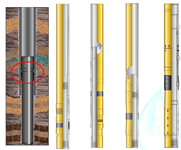
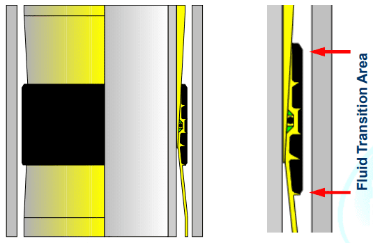
Pack Off Assembly
A critical component of a liner assembly is the liner- to-work string seal system, also known as the pack off assembly
The seal system must be able to withstand the anticipated differential pressure at the liner top to provide an effective seal between the drill pipe and the liner. And allow circulation at the end of the liner without fluid bypass at the liner top. The seal system has to be compatible with the liner assembly as well as the running tool, and may be configured as part of the running tool or as part of the liner hanger assembly.
Placing the seal system below the running tool during cementing operations provides isolation of the running tool from the cement slurry pumped down the drill pipe. Although, the effective areas, (the areas affected by annular and drill pipe pressure) will determine the net force on the end of the drill pipe. When differential pressures occur at the liner top, particularly when releasing the running tool.
There are a variety of liner-to-work string seal systems used in liner installations. Each system requires an analysis of its design to evaluate it technically as well as economically.
Wiper Plugs
We always use a liner wiper as a mechanical barrier between the cement and the displacement fluid. It displaces the cement and also wipes the liner ID, removing any cement or debris that may be clinging to it.
Drill Pipe Dart
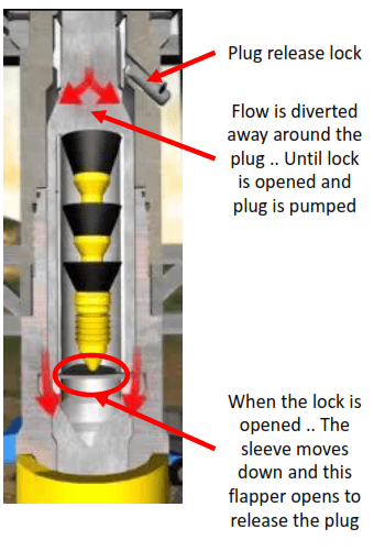
A drill pipe dart acts nearly identically to a wiper plug except that it displaces the cement in the drill pipe and wipes the drill pipe ID. The drill pipe dart lands in the liner wiper plug and is used to launch it from the bottom of the running tools. The drill pipe dart features an anti-rotation ring, which locks it in position when it latches into the wiper plug.
Landing Collar
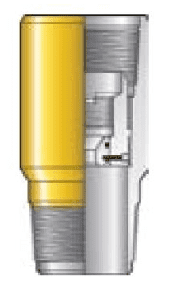
A casing liner hanger systems landing collar works to stop the wiper plug before it reaches the float equipment. All sizes and models of landing collars feature an anti-rotation mechanism; most sizes and models also feature a latch-down design that provides a positive seal in both directions.
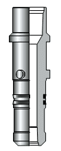
Seal Nipple & Packers
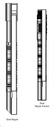
What Is Seal Nipples?
Seal nipples engage an existing tie-back seal receptacle to provide the necessary seal between the existing liner and the tie-back string casing to facilitate the extension of the liner to a point up the hole. You can install a seal nipple on the bottom of a casing string to extend the liner to the surface (tie back installation) or on the bottom of a liner to extend the liner further up the hole (tie back stub liner installation).
The seal nipple must correspond in length to the existing tie-back seal receptacle to provide the necessary isolation and support of the tie-back seal receptacle, as previously discussed.
The tie-back casing string can be cemented in place, or a retrievable non-cemented installation can be used. Non-cemented tie-back installations require the seal nipple to be of sufficient length to compensate for any length changes of the casing. Which occur due to changes in the temperature or pressure after the seal nipple has been installed.
Like other liner assembly components, the designing and manufacturing of the seal nipples are to have the same physical properties of the casing. As seal nipples are designed to seal in the appropriate tie-back seal receptacle, their pressure ratings will equal those of the casing and will allow unrestricted passage of other down-hole tool assemblies.
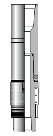
Seal Nipple Packers
Seal nipple packers are particular liner packers that incorporate the operational features of both a liner top packer and a seal nipple to provide annular isolation at the liner top between the tie back seal receptacle and the supporting casing. We utilize it to repair liner top leaks in lieu of performing a cement squeeze. Commonly, installing seal nipple packers is after the installation of a liner to guard against a potential liner top leak by providing a secondary seal to the existing competent cement seal.
Seal nipple packers can be designed to engage an existing tie back seal receptacle with the capability to perform future tie back operations or they can be configured to adapt to the bottom of a tie back casing string with no tie back provisions. Hold down slips can be incorporated in their design to anchor the packer in place preventing upward movement.
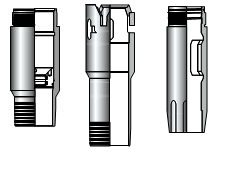
Casing Liner Hanger System Running Tools
There is a variety of running tools from which to choose when installing a liner. However, the tool chosen must:
- First, to act as a mechanism to adapt the liner to the setting string.
- Second, to carry the liner in the hole and position the liner at the desired setting depth
- Third, to release from the liner positively and efficiently without loosening the threaded connections of the drill pipe .
- Forth, be compatible with the liner assembly’s setting mechanism.
- Fifth, to be of sufficient design and material strength to meet the tensile requirements of both the liner casing and the drill pipe.
Mechanical Release Running Tool
Left Hand Release
Let’s have a look on an industry standard liner running tool:
- It uses a coarse left-hand threaded nut to carry the liner in the hole.
- To disconnect from the liner, rotate the setting tool to the right to unthread the nut from a compatible profile in the liner assembly.
- The use of a bearing in the liner hanger setting tool’s design allows for positioning of the drilling pipe in a compressive state to aid in releasing.
- We use this type of tool to run and release both hydraulic set and left-hand mechanical set liner hangers. Avoiding right-hand rotation is a must until releasing the liner system.
Right Hand Release
In liner hanger installations systems where right handset mechanical liner hangers are used, liner running tools that include drive dogs are used. With the running nut of the running tool threaded into the liner assembly and the mandrel in the tension, the drive dogs will engage in a spline immediately below the running thread.
- By rotating the drill pipe to the right, the engagement of the dogs in the spline does not allow the running nut to turn and release from the liner assembly.
- By rotating the drill pipe at the surface the torque will transfer through the setting dogs on the running tool into the spline of the liner assembly, thus turning the liner assembly.
- To release the running tool from the liner assembly, change the position of the running tool mandrel from the tension position to either the neutral or compression position. (where the weight of the liner is not being supported). Then right-hand rotation will now release the running nut from the liner.
Jay type running tools
Jay type running tools are alternatives to the spline type system. They are commonly used when installing relatively short liners in close tolerance installations where rotation of the liner is desired. Rather than using a setting dog and a spline for torque transfer. The TNJ transfers torque into the liner assembly when the jay lug on the running tool shoulders against the side of the jay slot.
The jay slot design is used when spline machining is not practical due to the dimensional limitations in installations, such as running a 101.6 mm O.D. liner inside 139.7 mm O.D. casing.
Jay-type running tools offer relatively low-cost options where rotation capabilities are required. However, these running tools have operational limitations which must be considered prior to the installation:
- Tensile rating is reduced due to the limited material cross sectional area of the jay slot.
- Torque capabilities are reduced due to the limited material cross sectional area of the jay slot.
- Controlling residual torque below the running tool to prevent premature disconnection of the liner is difficult.
Hydraulic Release Running Tool
Hydraulic release running tools are recommended for installations where the liner may require rotation while applying tension or compression forces on the end of the liner to reach the desired setting depth ( Read more avout : Casing Setting Depth Selection) due to hole geometry or hole conditions. Under these conditions, a running tool which have the following advantages:
- First, it will not release prematurely when rotating the liner to the right,
- Second, it won’t release due to the build up of residual torque in the open hole, is required:
- Third, it will for sure allows the liner to be drilled into place.
Mechanism
Instead of a threaded nut to carry the liner in the hole and setting dogs to engage splines for right hand rotational capabilities. So, the hydraulic release running tool uses a collet for carrying and releasing from the liner and inter locking castellation for rotation of the liner.
To release the running tool from the liner, the position of the mandrel under the collet is changed by creating a differential pressure at the running tool. When the mandrel position changes, the collet, no longer supported, collapses and disengages the liner assembly.
If the setting tool does not hydraulically release, then the mechanical release feature of the setting tool can be initiated. By applying sufficient torque, the rotational lock will shear allowing the mandrel to move downward. Thus positioning the collet in a collapsed and non-supported position disengaged from the running sub (Drilling Subs) in the liner hanger.
Check popular casing liner hanger running tools catalogs & datasheets: Liner Hanger Running and Service Tools – NOV, CRT Collet Running Tool for Liner Hangers | Schlumberger
Setting Collars, Top Set couplings, or Running Subs- Liner Carrying Mechanism
Liner hanger system carrying mechanisms provide a means to adapt the liner to the running tool and carry the liner in any oil and gas well during the installation.
Carrying mechanisms are identified as setting collars, top set couplings, or running subs. Although the terminology used to describe them is different. All three share one common purpose in their design: They provide a means to carry the liner in the well during installation.
The versatility of liner carrying mechanisms is best described by the following examples:
- Top set coupling is used in liner assemblies where a tie back receptacle and/or a setting sleeve will be used with a liner hanger or liner packer. The top set coupling threads to a liner assembly and provides a running thread compatible with the running tool. When assembled, the top set coupling is positioned inside either the tie back receptacle. Or the setting sleeve permitting whichever to be threaded to the liner hanger or liner packer.
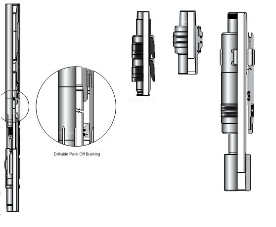
- The setting collar, threads directly to the liner with provisions to use a tie back receptacle and a drillable pack off bushing in the liner to work string seal system.
- Another type of setting collar is used in conjunction with a jay type running tool. It may be used with liner assemblies with or without a tieback seal receptacle. Or it can be designed with the appropriate connection to thread to a liner hanger.
- Running subs incorporate a running thread and splines in their design to provide the liner system with right hand rotation capabilities without premature disengagement of the running tool. Additionally running subs may have tie back receptacle provisions.
Setting Tools
Casing Liner Hangers Setting tools are used in conjunction with running tools when installing liner assemblies with liner top packers. These setting tools do not have a mechanism to carry the liner in the hole and are commonly confused with liner running tools due to their similar names.
Typically, setting tools are used to mechanically activate the elements of the liner top packer by engaging the setting tool with the top of the liner packer. And applying a compressive force after the running tool has been released from the liner. Therefore, the setting tool is installed above the running tool in either the setting sleeve or the tie back receptacle of the liner packer. In this position, the spring loaded setting dogs are retained in a retracted position.
When the running tool is released from the liner and the drill pipe is raised. The setting dogs expand when the setting tool is pulled from the setting sleeve or the tie-back receptacle. Once the setting dogs expand the drill pipe is lowered until they contact the top of the setting sleeve or the tie-back receptacle. Lowering the drill pipe pushes the setting sleeve or tie back receptacle downward, energizing the packing elements.
Liner Hanger System Rating
Liner Hanger Hanging Capacity:
The hanging capacity rating of a liner assembly is determined by its ability to support the weight of the liner without deforming the liner hanger or the supporting casing.
These criteria determine the hanging capacity rating of any liner assembly:
- The nominal wall thickness and the material grade of the supporting casing.
- The surface area of the slip.
- The cross sectional area of the slip.
- The effective contact area of the slip and cone.
- The material strength of the cone.
- The cross sectional area of the cone.
- The number of slips.
- The bearing load rating, under static and dynamic conditions, of rotating liner assemblies.
Liner Hanger Burst and Collapse Pressure:
Which are the maximum pressures Liner can handle without failure from inside & outside of the casing liner hanger.
Liner Hanger Tensile Load Capacity
Tensile loading capacity is the maximum tensile load at which Liner Hanger can reach without failure happen. In other words, the maximum load of casing liner it can handle.
Other Liner Hanger Ratings:
- Maximum Torque Strength
- Maximum OD
- Minimum ID
- Drift Dimension
Liner Packer Rating
- Running Tool Profile
- Burst and Collapse Pressure
- Tensile Load Capacity
- Maximum Torque Strength
- Maximum OD
- Minimum ID
- Drift Dimension
- Pressure and Temperature Strength
Setting Tool Rating
- Tool Profile
- Burst Pressure
- Tensile Load Capacity
- Maximum Torque Strength
- Maximum OD
- Minimum ID
Important Notes
- All equipment must have at least casing liner hanger strength values
- For all rating parameters (collapse, burst, tensile load etc.) the weakest point in design should be determined
- There should not be an ID constriction affecting the operation
Reference: Weatherford Liner Hanger Applications – Liner hanger design and operations
How to download it
download what
download the manual