These oil and gas rig elevators will support the oilfield drill pipes while raising from or lowering into the hole. We lock the elevator around the pipe with its hinge on one side and a latch on the other. The elevators hold the pipe directly below the tool joint.
We can sub-divide elevators into:
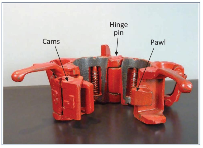
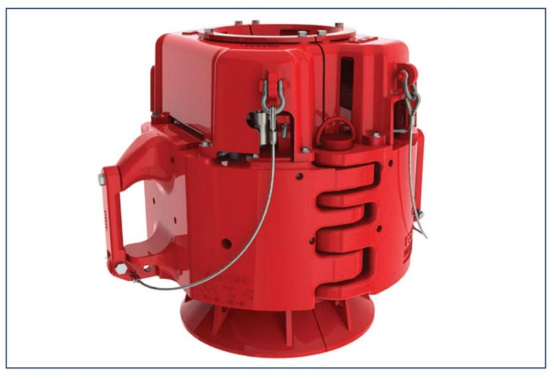
- Centre latch elevators (Figure 1).
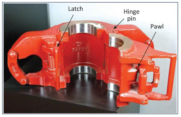
- Side-door elevators (Figure 2).
Or, we may sub-divide into:
- Collar type elevators: a 90° shoulder supports the string.
- 18° type elevators: here, an 18° external upset of the drill pipe (API drill pipe specifications) transmits the load.
- Slip-type elevators: slips grip the pipe body to support the string.
In addition to the above-mentioned drill string elevators, we use special oil rig elevators for casing running operations.
Drill Pipe Elevator Specifications
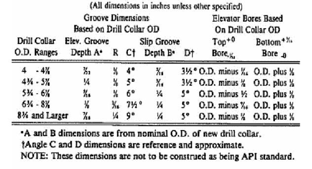
Drill pipe elevators for usc with taper shoulder and square shoulder weld-on tool joints shall have bore dimensions as specified in Table 1.
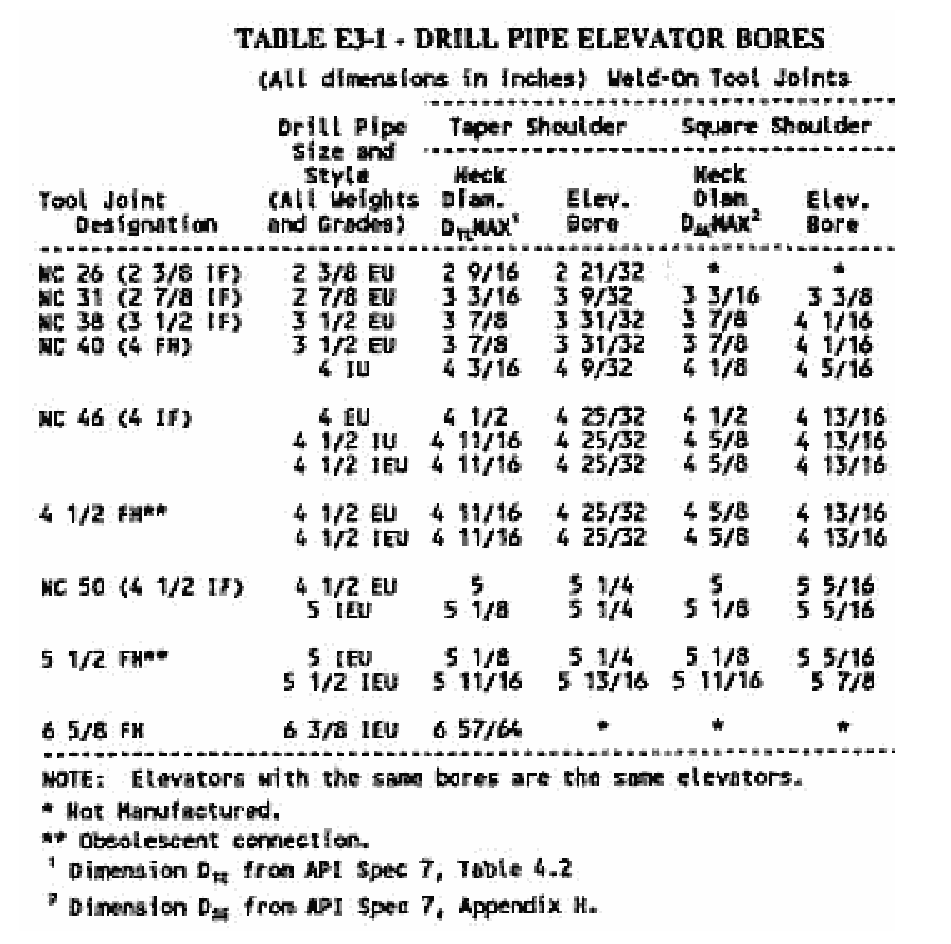
Notes on Table 1: Oilfield elevators with identical bores are the same.
- * Not Manufactured.
- ** Obsolescent connection.
- 1 Dimension DTE from API Spec. 7, Table 4.2
- 2 Dimension DsE from API Spec. 7, Appendix H.
The Latch Mechanism
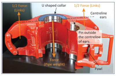
A very close fit of the hinge pin and pawl significantly affects the correct functioning of an elevator – especially the center-latch elevator.
If there is play in the hinge, the elevator tends to open from the bottom (see Figure 2), and tensile force will have to be borne by the latch mechanism. This results in cracks and possible breakage of the latch. The U-shape of the side-door elevator makes this less likely. The pin and pawl are not affected by the bending moment exerted by the links in the ears (see Figure 4).
Each elevator has a safety latch which consists of a locking pawl that grips, activated by springs, behind cams. Almost all makes have an extra safety device that prevents the locking pawl from working loose while lifting or lowering the string.
Support Mechanism For Drill Pipe Elevators
Collar-Type Elevators
The coupling, which rests with its shoulder on the elevator, will support the weight of the entire string. If the elevator bore is not a proper fit, the coupling will not rest centrally on the elevator. Furthermore, there will not be a good distribution over the two ears and links. As a result, the elevator may be overloaded with all the consequences involved.
18° Type Elevators
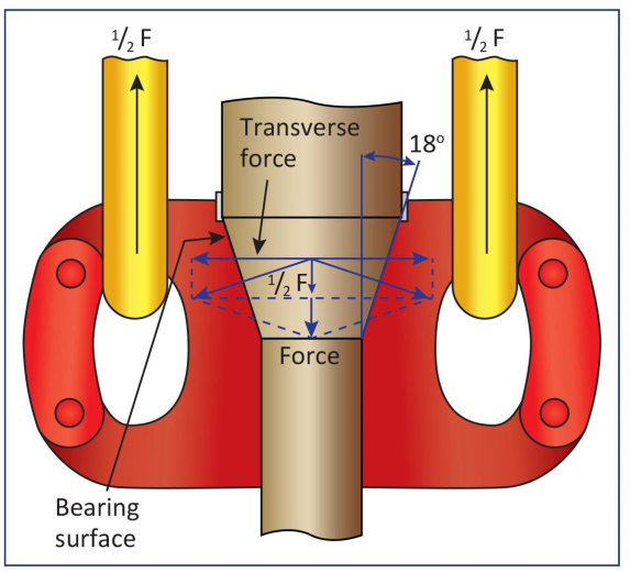
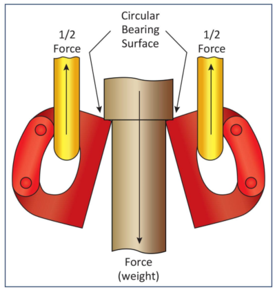
Elevators with an 18° conical opening are identical to the drill pipe. There will be an outward force (Figure 5), meaning the elevator tends to bend open. It is, therefore, essential that the latch works correctly. The lip at the back of the elevator, if present, helps to keep the elevator closed.
Slip-type elevators
This type of drill pipe elevator prevents excessive force from exerting on upsets or couplings of casing or tubing. The slip-type elevator has replaceable segments with inserts or dies.
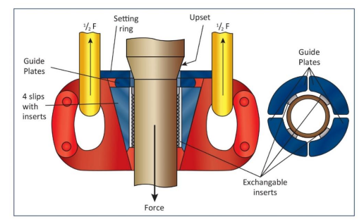
The upset or tool joint collar will push a setting ring that will cause pushing the slips into the tapered space. The inserts will now grip the pipe body and take over the load. Slip springs push the slip segments free from the pipe when releasing the load.
We must keep the inserts clean. If the inserts are dirty, the oil rig elevator may not grip, exposing the setting ring to heavy loads. We must dismantle the elevators when cleaning or exchanging the inserts.
We mainly use this type of elevator with tubing. Many refer to it as a YT elevator, in fact, a brand name. The slip-type drill pipe elevator can suit various pipe diameters by installing the proper size slip segments and slip-setting ring assembly. As for all center-latch elevators, a latch lock is provided in addition to the spring-type latch to reduce the possibility of the elevator opening under load.
Special Casing Elevators
In addition to the side-door elevator, single-joint and slip-type casings are used in running casing.
We use a single-joint elevator (Figure 7) to pull a single casing joint from the V-door into the oilfield rig derrick until screwing the joint into the previous one. We can suspend the single-joint elevator from the hook using the long wire rope sling with a swivel. In addition, we should never use them for lifting more than one joint.
Spider elevators are heavy-duty oil rig elevators that we can use for handling long, heavy casing strings (Figure 8). They are convertible, and we can use them as casing spiders. They are one-man operated through a unitized slip assembly and locking mechanism. We can install a top guard and guide plates when using them as a spider. Furthermore, we can add a casing guide bell to the BTM for quick stabbing when using them as elevators.
Small-size spiders are primarily manually operated. Larger sizes may be operated by air-powered control.
Operation As An Oilfield Elevator
After making up the new joint, we can lower the slip-type elevator over the joint with the slips in the up position. Derrick man then releases the slip lock, activating the slips that automatically grab the casing. Once suspending the string in the slip-type elevator, the slips of the spider are automatically released and can be raised by the rig floorhand with the yoke handle to lock them in the up position.
Operation As A Spider
Lower the casing through the spider, which rests on the rotary with slips in the up position. To set the slips, release the lock, and the slips fall into place. Use a yoke handle or air valve operation to operate the slips. After making up the next joint and pulling the casing is up, operate the yoke handle or air valve to raise the slips. Once raised, the slips again lock automatically in the up position. An upper guard assembly gives added protection against damage to the spider slip assembly.
Many prefer a casing spider to casing slips because its gripping surface is much greater, and the load distribution is more evenly. The oilfield slip-type casing elevators also help to prevent shock loads between the coupling and elevator.
Checks For The Proper Use Of Drill Pipe Rig Elevators
The following checks apply to all types of elevators. For a quick reference to critical points of the drill pipe elevators, see Figure 29.
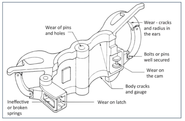
- Is the oilfield elevator size correct?
- Are the dies of slip-type elevators sharp?
- Are the hinge pin or holes worn?
- Are there any body cracks, and is the gauge correct?
- Is the latch cracked or worn (pawl, cams, broken springs)?
- Are the links long enough?
- When was the last inspection?
Care and Inspection Procedures
Since both care and inspection procedures depend primarily upon the amount of service the equipment has had, it is challenging to project overall recommended practice. MAny suggest the following as a starting point from which companies may vary according to their needs.
Before Each Round
Examine all drill pipe elevators should to determine if the latch and the latch-lock mechanism are functioning correctly. Lubricate hinge pins, latch lug, and link contact surfaces. Check slip-type casing and tubing elevators for sharp dies. Remove the slip segments for cleaning and lubrication.
Semi-annual Check For Drilling Rig Elevators In Oil & Gas
This examination, as outlined below, whether conducted in the field or shop, should be made using calibrated instruments to determine any deviations from the manufacturer’s technical data for original parts.
- Square shoulder collar-type drill pipe, casing, and standard tubing elevators: Inspect the collars for squareness, uniformity, and wear depth. Uneven wear, or worn recesses of 1/16 in. or more, require refacing of collar surface. Visual inspect the hinge pins and springs for excess wear and obvious weakness.
- 18 deg. Taper-type oilfield elevators: inspection is the same as for square shoulder, except that we should observe & measure the conical bore and (in many instances, this check should be more frequent). Measure all tool joints used with these elevators. Check the amount of wear the chart, Table 2.
In addition to the angle of the taper, check the hard banding to see if it extends beyond the taper. Any straight edge may be used for this purpose.