The Dump Bailer is a tool that we can run on a wireline. It facilitates placing the required cement on top of a bridge plug. The release of a weight bar displaces cement from the bailer sections. The plug can undergo a pressure test 24 hours after the last bailer run, when the cement has reached about 90% of its maximum compressive strength. The temperature rating & size of the Dump Bailer are different from one manufacturer to another.
There are different types of activation systems available in oil and gas:
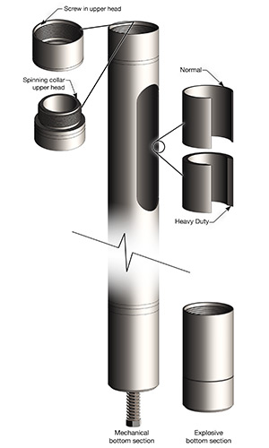
- Using a small blasting cap above the glass rupture disc, that we can actuate when required.
- Using a mechanical striker pin: When the dump bailer strikes a bridge plug with force, the pin will hit & puncture shear disc.
- Using a time delay: After time expires, the well pressure floods a hydrostatic chamber in the actuator; this force will fully open the valve sleeve.
Applications
- Seal off nonproductive zones
- Seal off water-producing zones below productive zones.
- Base for a sand plug.
- Low-pressure acid base plug.
- Positive depth control plug.
Mechanical Specifications
- Temperature rating
- Pressure rating
- Borehole size (min – max).
- Outer diameter
- Length
- Weight
Dump Bailer Operations
Tool String Components
The wireline string will be made up according to the well profile and composed by:
- Rope socket
- Stem
- Knuckle joint
- 3ft stroke Mechanical Jar
- Dump bailer suitable for the operation.
Job Preparation
- For particularly deviated wells and/ or in the presence of doglegs, the maximum rigidity will be not more than 6ft.
- To ensure accurate measurements, it is recommended to perform a calibration using a gauge cutter that has the same size as the tubing drift. Alternatively, you can use a gauge cutter that has a diameter 0.1mm smaller than the ID of the Landing Nipples that you will be crossing. In either case, the gauge cutter should not be smaller than the OD of the Dump Bailer. Perform the calibration up to the depth that has been decided.
- Revise the Dump Bailer with a suitable diameter and dimensions. Replace any damaged parts, verify the shearing parts, and remove the Top Sub.
- Comply with applicable laws and use personal protective equipment when filling the Dump Bailer. Reattach the Top Sub to the Dump Bailer, taking care not to damage the Body.
- Screw the Dump Bailer onto the wireline string, paying attention to possible fluid leaks from the Equalizing Port of the Top Sub, and pull it into the Lubricator.
- Perform the lubricator assembling procedure and the Wellhead valve opening procedures.
Dump Bailer Running Procedure
- Run in the hole. Cross wellhead valves and tubing hanger at a very limited speed (not more than 5m/min). While running at maximum speed, slow down to 10m/min and carefully cross the completion restrictions (Landing Nipples, Crossovers, SCSSV) based on wire type, well deviation, and fluid in the well.
- Perform weight indication pull every 100m and last 50m before reaching estimated bottom hole depth. Perform more pulls if necessary.
- Please proceed very slowly to reach the bottom hole without any sudden jarring movements.
- Initiate a precise monitoring of tubing pressure.
- Ensure being at the desired depth before releasing it. Then, jar down once to shear the shear pin.
- Wait for the fluid to completely exit the dump bailer before proceeding.
Pulling The Dump Bailer
- POOH: With the wireline string at 100m, slow down to 10m/min until zero m.
- Slow down the unit to the minimum speed possible. At this point, the operator will position himself between the unit and the load cell of the weight indicator. He will apply pressure on the wire with both arms to detect and reduce any sudden movement between the rope socket and the stuffing box. If he detects any such contact, he should immediately inform the Chief Operator without any doubt.
- The operator is responsible for closing the wellhead valve and counting the turns. Slowly close the swab valve.
- To bleed the pressure of the lubricator, release it gradually via the needle valve.
- Perform the procedure to extract tools from the lubricator.
- Redress the Dump Bailer and repeat the necessary runs.
- At the end of the operation, perform the rig down procedure.